1
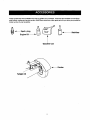
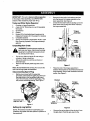
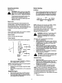
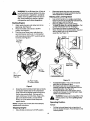
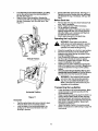
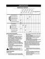
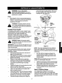
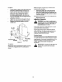
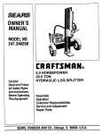
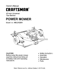
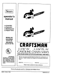
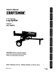
/
Owner's Manual
[I:RR
/
/
22 Ton Hydraulic
Log Splitter
Model No.
247.794500
Ii
I!
CAUTION: Before using this product,
read this manual and follow all Safety
Rules and Operating Instructions.
Sears, Roebuck And Co., Hoffman Estates, IL 60179, U.S.A.
Printed in U.S.A.
770-10035A
(7/99)
/
U
Content
Page
Content
Page
Warranty Information.........................................
2
Maintenance ......................................................
14
Safe Operation Practices ................................... 3
Service & Adjustment ........................................
17
Accessories .......................................................
7
Off-Season Storage ...........................................
19
Assembly ...........................................................
8
Trouble-Shooting...............................................
20
Operation ...........................................................
10
Parts List............................................................
22
ONE-YEAR
WARRANTY ON CRAFTSMAN
LOG SPLITTER
For one year from the date of purchase, when this Craftsman log splitter is maintained, lubricated, and tuned up
according to the operating and maintenance instructions in the operator's manual, Sears will repair, free of
charge, any defect in material or workmanship.
This warranty excludes the tires, spark plug, oil filter and air cleaner, which are expendable parts and become
worn during normal use.
If this log splitter is used for commercial or rental purposes, this warranty applies for only 30 days from the date
of purchase.
WARRANTY SERVICE IS AVAILABLE BY CONTACTING THE NEAREST SEARS SERVICE CENTER IN THE
UNITED STATES. THIS WARRANTY APPLIES ONLY WHILE THIS PRODUCT IS IN USE IN THE UNITED
STATES.
This warranty gives you specific legal rights, and you may also have other rights which vary from state to state.
Sears, Roebuck and Co., Dept. 817WA, Hoffman Estates, IL 60179
Horsepower: ......................... 5.0
Engine Oil .............................. SAE 30/1.25 pints
Fuel Capacity: ....................... unleaded/1.25 qts.
Hydraulic Fluid ...................... Dexron III/4 gallons
Tire Pressure ......................... 30 p.s.i, maximum
Spark Plug (Gap .030") .......... Champion RJI9LM
Magnetron Ignition Air Gap.....0125"
Model Number..2..4,7.:7..9.4..5.0,0.
...................................
Serial Number ...........................................................
Date of Purchase ......................................................
Record model number, serial number and date of
purchase of the log splitter and keep in a safe place
for future reference.
Thissymbol points
out important safety instructions which, if not followed,could endangerthe personalsafety and/or propertyof youmelfand others. Read and follow all instructionsin this manualbefore
attempting to operateyour logsplitter.Failureto complywith these instructions may resultin personal injury.
When you see this symbol--heed its warning.
Your log splitter was built to be operated according to the rules for safe operation In this
manual, As with any type of power equipment, carelessness or error on the part of the operator can result in serious injury, if you violate any of these rules, y_u may cause serious
injury to yourself or others,
The engine exhaust from this product contains chemicals known to the state of California to cause
cancer, birthdefects or other reproductive harm.
Towing
•
•
•
•
•
•
•
•
•
This unit should not be towed on any street,
highway or publicroad without checking the
existing federal, local or state requirements.
Such information may be obtained by calling your
state or local bureau of motor vehicles. Any
licensing or modificationsneeded to comply with
federal, local or state vehicle requirements is the
sole responsibilityof the purchaser.
Make sure you follow the wiring diagram color
codes when installing the light kit on the log
splitter. (e.g. ground to ground, left turn to left
turn, etc.). Failure to wire unit correctly may
cause the tow vehicle wiring to overheat and/or
the log splitter lights to operate incorrectly. It may
be necessary to replace the turn signal flasher
unit in your tow vehicle if it is not capable of
operating the additional lights on the log splitter.
Before towing the log splitter on a street, highway
or public road, verify that all lights are functioning
properly and the yellow side reflectors are in
position. Replace bulbs if they are burnt out.
Before towing, always check to be certain the log
splitter is correctly and securely attached to the
tow vehicle, and safety chains are in place.
Leave slack in chains for turning allowance.
Use a class I or higher hitch with a 1-7/8" ball.
Keep ball socket and clamp face lubricated with
chassis grease.
Be sure the coupler is secured to the hitch ball
and the lock lever is down tight and locked.
Check vehicle hitch, ball and coupler for signs of
wear or damage. Replace any parts that are worn
or damaged before towing.
The coupler must be secured to the log splitter
tongue tube with the original equipment bolts and
nuts. See your authorized service dealer for
replacement parts. Coupler nuts should be
tightened securely (20 foot pounds).
Make sure beam assembly is securely latched in
•
•
•
•
the horizontal position and jack stand (if provided)
is pivoted and secured in the up position before
towing log splitter, Never tow with the beam in
vertical position.
Do not tow the log splitter faster than 45 MPH.
Higher speeds may damage log splitter.
Excessive high speeds may cause the logsplitter
to =fishtail" or otherwise become unstable.
Check the tire pressure on the log splitter tires. It
must be 30 p.s.i. MAXIMUM for highway travel.
When parking, storing or using your logsplitter,
keep the coupler off the ground so dirtwill not
build up in the ball socket.
Do not allow anyone to sit or ride on your log
splitter. They can easily fall off and be seriously
injured.
Training
•
•
•
•
3
Before operating this log splitter, read and
understand this operator's manual completely.
Become familiar with itfor your own safety. To fail
to do so may cause serious injury. Do not allow
anyone to operate your log splitter who has not
read this manual. Keep this manual in a safe
place for future and regular reference and for
ordering replacement parts.
Never use your splitter for any other purpose than
splitting wood. It is designed for this use and any
other use may cause an injury. Your log splitter is
a precision piece of power equipment, not a toy.
Therefore, exercise extreme caution at all times.
Never arrow children to operate your log splitter.
Do not allow adults to operate it without proper
instruction.Only persons well acquainted with
these rules of safe operation should be allowed to
use your log splitter.
Only the operator is to be near your log splitter
during use. Keep all others, including pets and
children, a minimum of 20 feet away from your
work zone. Flying wood can be hazardous. If a
helper is assisting in loading logs, never activate
the control until the helper is clear of the area,
More accidents occur when more than one
person operates the log splitter than at any other
time.
No one should operate this unit while intoxicated
or while taking medication that impairs the
senses or reactions. A clear mind is essential for
Horizontal Operating Position: Stand behind
the reservoirtank. See illustrations.
safety. Never allow a person who is tired or
otherwise not alert to use your log splitter.
Preparation
•
•
•
•
•
•
•
•
•
•
•
•
•
Never wear loose clothing or jewelry that can be
caught by moving parts of your log splitter and
pull you into it. Keep clothing away from all
moving parts of your log splitter.
Wear proper head gear to keep hair away from
moving parts. Always wear protective hearing
devices as needed.
Always wear safety shoes. A dropped log can
seriously injure your foot.
Always wear safety glasses or goggles while
operating your splitter. A piece of splittinglog
could fly off and hit your eyes.
Wear leather work gloves. Be sure they are tight
fitting without loose cuffsor draw strings.
Use your log splitter in daylight, or under good
artificial light.
Never operate your splitter on slippery, wet,
muddy or icy surfaces. Safe footing is essential
in preventing accidents,
Never operate your splitter while attached to a
towing vehicle.
Only operate your splitter on level ground and
not on the side of a hill. It could tip, or rolling logs
or poor footing could cause an accident.
Operating the splitter on level ground also
prevents the spillage of gasoline from the fuel
tank.
Never attempt to move the log splitter over hilly
or uneven terrain without a tow vehicle or
adequate help.
Always block the wheels to prevent movement
of log splitter while in operation.
Check the fuel before starting the engine.
Gasoline is an extremely flammable fuel. Do not
fill the gasoline tank indoors, when the engine is
running, or while the engine is still hot. Replace
gasoline cap securely and wipe off any spilled
gasoline before starting the engine as it may
cause a fire or explosion.
Both ends of each log must be cut as square as
possible to help prevent the log from riding out of
the splitter during operation.
Operation
•
Vertical Operating Position: Stand in front of
the logsplitter.
Know how to stop the unit and disengage the
controls.
Never place hands or feet between log and
splittingwedge or between log and end plate
during forward or reverse stroke. To do so may
result in crushed or amputated fingers or toes, or
worse, you may lose an arm or foot.
Do not straddle the splitter when using it. A slip
in any position could result in a serious injury.
Do not step over your log splitter when the
engine is running. You may trip or accidentally
activate the splittingwedge if you step over. If
you need to get to the other side, walk around.
Never try to split two logs on top of each other.
One may fly out and injure you.
When loading the log splitter, place your hands
on the side of the log, not at the ends. Never
attempt to load your splitter while the splitting
wedge is in motion. You may get caught by the
wedge and injured,
Only use your hand to operate the splitting
wedge or control lever, Never use your foot or a
rope or any other extension device. This could
result in your inability to stop your splitter quickly
enough to avoid injury.
Always keep fingers away from any cracks that
open in the log during splitting operation. They
can quickly close and pinch or amputate your
fingers.
•
•
•
•
•
•
•
•
•
Never attempt to split woods across the grain.
Some types of wood may burst or fly out of your
splitter and result in injuryto you or a bystander.
For logsthat are not cut square, the longest
portion of the log should be rotated down and
the most square end placed against the splitting
wedge.
Keep your work area clean. Immediately
remove split wood around your splitter so that
you do not stumble over it. Clean chips and dirt
off end plate (wood platform) after each log is
split, or whenever necessary to maintain flat
contact between wood and end plate (platform).
Never move the tog splitter while the engine is
running.
Never leave your log splitter unattended with the
engine running. Shut off the engine if you are
leaving your splitter,even for a short period of
time. Someone could accidentally activate the
splittingwedge and be injured.
Do not run engine in an enclosed area. Exhaust
gases contain carbon monoxide. This odorless
gas can be deadly when inhaled.
Be careful not to touch the mufflerafter the
engine has been running. It will be HOT!
If the equipment should start to vibrate
abnormally, stop the engine and check
immediately for the cause. Vibration is generally
a warning of trouble.
When cleaning, repairing or inspecting, make
certain all moving parts have stopped.
Disconnect the spark plug wire and keep the
wire away from the plug to prevent accidental
starting.
Customer
•
•
•
•
•
•
•
•
•
•
•
•
•
Responsibilities
•
Do not operate your splitter in poor mechanical
conditionor when in need of repair,
Periodically check that all nuts, bolts, screws,
hose clamps and hydraulicfittings are tightto be
sure equipment is in safe working condition.
Where appropriate, check all safety guards and
shields to be sure they are in the proper position.
Never operate your splitter with safety guards,
shields or other protective features removed.
These safety devices are for your protection.
Replace all damaged or worn parts such as
hydraulic hoses and fittings immediately with
manufacturer approved replacement parts.
Do not change the engine governor settings or
overspeed the engine. This increases the
hazard of personal injury. The maximum engine
speed is preset by the manufacturer and is
within safety limits.
Do not alter your log splitter in any manner such
as attaching a rope or extension to the control
lever or adding to the width or height of the
•
•
•
wedge. Such alterations may cause your splitter
to be unsafe.
Perform all recommended maintenance
procedures before you use your splitter.
Do not service or repair your log splitter without
disconnectingthe spark plug wire and moving it
away from the spark plug.
Never store the equipment with gasoline in the
tank inside of a buildingwhere ignitionsources
are present, such as hot water and space
heaters, clothes dryers and the like. Allow the
engine to cool before storing in any enclosure.
Always store gasoline in an approved, tightly
sealed container. Store the container in a cool,
dry place. Do not store in a building where
ignitionsources are present.
To reduce fire hazard, keep engine free of grass,
leaves, wood chips, and excessive grease and
oil.
The hydraulicsystem of your logsplitter requires
careful inspection,along with the mechanical
parts. Be sure to replace frayed, kinked, or
otherwise damaged hydraulic components.
Fluid escaping from a very small hole can be
almost invisible. Do not check for leaks with your
hand. Escaping fluid under pressure can have
sufficientforce to penetrate skin, causing
serious personal injury. Leaks can be located by
passing a piece of cardboard or wood over the
suspected leak and looking for discoloration.
Should it become necessary to loosen or
remove any hydraulic fitting or line, be sure to
relieve all pressure by shuttingoff the engine
and moving the control handle back and forth
several times.
Do not remove the cap from the hydraulic tank or
reservoirwhile your log splitter is running. Hot oil
under pressure could cause injury.
The pressure relief valve on your splitter is
preset at the factory. Do not adjust the valve.
Only a qualified service technician should
perform this adjustment.
Completely drain fuel tank priorto storage. This
guards against accumulation of fuel fumes
which could result in a fire hazard.
Never store log splitter outside without a
waterproof cover. Rain will cause rust on the
inside of the cylinder.
Important Information
Always:
•
•
•
•
5
Use clean fluid and check fluid level regularly.
Use Dexron III Automatic Transmission Fluid or
10W non-foaming hydraulic fluid.
Use a filter (clean or replace regularly).
Use a breather cap on fluid reservoir.
•
•
•
•
•
•
•
•
Make certain pump is mounted and aligned
properly.
Use a flexible "spider" type coupling between
engine and pump drive shafts.
Keep hoses clear and unblocked.
Bleed air out of hoses before operating.
Flush and clean hydraulic system before startup after any malfunction or servicing.
Use "pipe dope" on all hydraulic fittings.
Allow time for warm-up before splittingwood,
Prime the pump before initialstart-up by turning
over the engine with spark plug disconnected.
•
Split wood with the grain (lengthwise) only.
Never:
•
•
•
•
•
•
•
•
Use when fluid is below 20 ° F, or above 150° F,
Use a solid engine/pump coupling.
Force pump when mounting.
Operate through relief valve.
Attempt to adjust unloading or relief valve.
settings without pressure gauges.
Operate with air in hydraulic system.
Use Teflon tape on hydraulicfittings.
Attempt to cut wood across the grain,
Theseaccessories
wereavailable
when the log splitter was purchased. These are also available at most Sears
retail outlets, catalog and service centers. Most Sears stores can order repair parts for you when you provide the
model number of your log splitter.
Gasoline
Can
-<_Fender
Tailight Kit
IMPORTANT: This unit is shipped without gasoline
in the engine. After assembly, see OPERATION
section of this manual for proper fuel fill-up.
•
Tools and Other Items Required
•
1.
2.
3.
4.
5.
6.
7.
Crowbar or Large Screwdriver
A pair of 9/16" Wrenches or a set of Adjustable
Wrenches
Screwdriver
Cutters
Remove the two bolts, lock washers and hex
nuts that secure the tongue assembly to the
beam assembly. See Figure 2.
Unlockthe two beam locks by pullingout on the
beam locks and pivotingthem down. Remove
the tongue assembly.
Tongue
Assembly
Engine Oil for lubricating beam (equipment is
shipped with engine oil in the engine for starting)
Unleaded Gasoline
Dexron III Automatic Transmission Fluid or 10W
Beam
Non-Foaming Hydraulic Fluid (approximately 4
gallons)
Unpacking
from Crate
WARNING: Exercise extreme caution as
parts are very heavy. Mechanical handling
equipment or sufficient manpower should
be used to prevent injury.
•
•
•
Pry the top, sides and ends off crate using a
crowbar or large screwdriver.
Set panels aside to avoid tire punctures or
personal injury.
Remove and discard plastic bag that covers
unit.
Lock Washers
and Hex Nuts
Figure 2
Note: Do not remove the banding from around the
tank until the log splitter is assembled.
Disconnecting
•
Place the end of the tongue assembly in
between the brackets on the wheel and reservoir
tank assembly. Secure with hardware removed
eadier. See Figure 3.
Spark Plug
Before you proceed with the assembly
procedure, disconnectthe spark plug wire from
the spark plug on the log splitter engine and
move the wire away from the spark plug. This
will prevent accidental starting. See Figure 1.
Bracket
Tongue
Nuts
Disconnect spark
plug wire here
Bolts
Lock
Figure 1
Setting Up Log Splitter
NOTE: All hardware needed for assembling your
Craftsman log splitter has been placed in position on
the equipment.
Figure 3
Remove the spring clipand the clevis pin from
the jack stand. Pivot the jack stand to the
8
operating position (90°), and secure with the
spring clip and clevis pin. See Figure 4.
Final Assembly
Tire Pressure
The tires may have been over-inflated for shipping
purposes. Maximum tire pressure should not exceed
30 p.s.i. Check tire pressure regularly.
Tongue
Preparing the Engine
•
•
•
Place the log splitter on a firm, level surface.
Check engine oil as instructed on page 11.
Fill engine with gasoline as instructedon
page 11.
Preparing the Log Splitter
•
Jack Stand
•
Lubricate the beam area where the splitting
wedge will slide with engine oil (do not use
grease). Make certain to oil both front and back
of the beam face.
Remove reservoir vent plug. See Figure 6.
Figure 4
•
•
•
•
Cut the two straps from around the reservoir
tank assembly
Remove lag screw and washer which secures
the beam assembly to the bottom of the crate.
Lower the beam assembly to its horizontal
position. Make certain the beam is locked
securely with the horizontal beam lock. See
Figure 5.
Puilthelogsplitteroffthepallet.
Fill hydraulic
Reservoir
Tank
Reservoir Vent
Plug
Figure 6
•
\
\
\
\
\
\
\\\_^
Vent
Plu
•
\
\
•
•
•
•
•
Beam Lock
,/
•
Fill the reservoir tank to about 2" from the top
with 4 gallons of Dexron III automatic
transmission fluid, or lOW non-foaming
hydraulic fluid. Replace vent plug securely
Disconnect the spark plug wire. Prime the pump
by pulling the recoil starter as far as it will go.
Repeat approximately 10 times.
Reconnect the spark plug wire and start engine.
Refer to starting instructions on page 12.
Use control handle to engage the wedge to the
far extended position. Refer to Figure 8.
Retract the wedge.
Refilltanktowithin 1-1/2"to2"fromthetopof
the tank.
Extendandretractthewedge
12complete
cycles to remove trapped air in the system
(system is "self-bleeding").
Refillthereservoirtowithin
1-1/2"to2"fromthe
top of the tank. Much of the original fluid has
been drawn into the cylinder and hoses. Make
certain to refill the reservoir, to prevent extreme
damage to the hydraulic pump.
NOTE: Some fluid may overflow from the vent plug as
the system builds heat and the fluid expands and
seeks a balanced level.
Move control handle BACK or UP to return the
wedge. See Figure 8 on page 11.
Figure 5
9
W
m
I|l
Know Your Log Splitter
Read this owner's manual and safety rules before operating your log splitter.Compare the
illustrations on this page with your equipment to familiarize yourself with the location of
various controls and adjustments. Save this manual for future reference.
The operation of any log splitter can result in foreign objects being thrown into the eyes,
which can result in severe eye damage. Always wear safety glasses, when operating your
log splitter,or while performing any adjustments or repairs on it.
Splitting Wedge
End
Plate
earn Assembly
\
Tongue Assembly
Reservoir Tank
Fuel Cap
_
011 Fill
Control
Handle
\
Beam
Locks
Plug
Figure 7
MEETS
ANSI SAFETY
REQUIREMENTS
Sears log splitters conform to the safety standards B71.7-1985 of the American National Standards Institute.
10
Operating
Before Starting
Controls
(See Figure 7.)
Oil Fill-Up
Only use high quality detergent oil rated with API
service classification SF, SG or SH. Select the
oil's viscosity grade according to the expected
operating temperature. Follow the chart below.
again
refer to the
safety
rules starting on
WARNING:
Before
usingyourlogsplitter,
page 3 of this manual. Always be careful.
Do not operate the log splitter withoutthe
proper amount of hydraulic oil in the
reservoir tank. Failure to refill the tank will
void your warranty.
Colder_91-_.
5W30
40°F_
]
Warmer
SAE 30
_-
Beam Locks
Used to secure the beam in the horizontal or the
vertical position. There are two beam locks, one for
each operating position. The vertical beam lock is
located next to the oil filter. The horizontal beam lock
is located on the beam support latch bracket.
NOTE: Although multi-viscosity oils (5W30, l OW3O,
etc.) improve starting in cold weather, these
multiviscosityoils willresult in increased oil
consumption when used above 40°F Check the oil
level more frequently to avoid poss,
_ngine
damage from running low on oil.
Primer
Used_s_rta
coldengine. Donotuse ff_res_rta
warm eng_e atterashortshuhdown.
&
Starter Handle
Used to manually start the engine.
Control Handle
Fill engine with the appropriate oil as follows:
•
Remove oil fill dipstick.
•
With log splitter on level ground, use a funnel to
fill engine oil to FULL mark on dipstick. Capacity
is approximately 1,25 pints or 21 ounces. Be
careful not to overfill.
•
Replace dipstick on to the engine and tighten.
Then remove the dipstickagain and wipe off the
oil from the end of the dipstick with a clean cloth.
•
Screw the dipstick firmly back toplace. Remove
to check the oil level.
•
Refill oil to FULL mark on dipstickff necessary.
Replace dipstick and tighten.
The controlhandle has three positions. See Figure8.
_
WARNING: SAE 30 oil, if used below 40°F,
willresult in hard startingand possible
engine bore damage due to inadequate
lubrication.
ReverseL ",---_
To returnw/ge
NeutralII To stop
con ' r
run
engine unless
oil level
is between
WARNING:
To avoid
engine
damage, FULL
never
and Add marks on the dipstick.
Gasoline FIll-Up
Figure 8
•
•
•
Move control handle FORWARD or DOWN to
move wedge down to split wood.
NOTE: Control handle will return to neutral position
as soon as handle is released.
•
•
Stopping
•
•
•
Release the control handle to stop the wedge
movement.
Move control handle BACK or UP to return the
wedge.
Remove fuel cap.
Make certain the gasoline container is clean and
free from rust or foreign particles. Never use
gasoline that may be stale from long periods of
storage in the container.
Fill fuel tank with about 1.25 quarts of clean,
fresh, lead-free grade automotive gasoline.
NOTE: DO NOT use gasoline containing methanol
Gasoline containing up to about 10% ethanol or up to
15% methyl tertiary butyl ether (MTBE) may be used,
but will require special care when engine is left
unused for extended period. See storage instructions
onpagel_
Engine
Move throttle control lever to STOP position.
Disconnect spark plug wire and move away
from spark plug to prevent accidental starting
while equipment is unattended.
•
11
Replace fuel cap.
&
WARNING: Do not fill closer than 1/2 inch of
top of fuel tank to prevent spills and to allow
for fuel expansion. If gasoline is accidently
spilled, move log splitter away from area of
spill.Avoid creating any source of ignition
until gasoline vapors have disappeared,
Starting
1.
2.
3.
•
Disconnect spark plug wire and move away.
from spark plug to prevent accidental starting
while equipment is unattended.
Raising and Lowering
°
Engine
Use control handle to run wedge up and down
beam 6 to 8 times to circulate the hydraulicfluid,
which will warm and thin the fluid.
Place log splitter on a firm, level surface.
To raise the beam for vertical operation: Pull
out the vertical beam lock on the tongue.
Pivot beam lock down to release the beam.
Move the beam to the vertical position.Secure it
with the beam lock on the reservoir tank
assembly. See Figure 10.
•
•
Attach spark plug wire and rubber boot to the
spark plug. See Figure 9,
Place the throttle controllever in START
position. See Figure 9.
Push the primer three times, wait about two
seconds between each push. In cold weather
Beam
•
•
with temperatures below 550 F, push the primer
five times, See Figure 9.
Vertical
Pull Starter
Loci
=' i
°o0 ®
\
\
\
\
\
Horizontal
Beam Lock
(_ Push
Primer
Attach Spark
Plug Wire
Figure 10
START
•
•
Figure 9
4,
Grasp the starter handle and pull rope out slowly
until engine reaches start of the compression
cycle (rope will pull slightly harder at this point).
Let the rope rewind slowly. Pull rope with a
rapid, continuous,full arm stroke. Keep a firm
grip on the starter handle. Let rope rewind
slowly. Do not let starter handle snap back
against starter.
•
To lower the beam: Pull out the horizontal
beam lock on the reservoir tank.
Pivot beam lock down to release the beam.
Carefully pull back on beam and lower itto the
horizontal position.See Figure 10.
Pull out the beam lock on the tongue, pivotit
upwards and release it to hold the beam. Make
certain it is latched securely.
vertical
positiononly
when
heavy
WARNING:
Always use
thesplitting
log splitter
in the
logs.
,_
Operating
NOTE: If engine does not fire after three attempts,
repeat above instructions.
Vertical
Stopping Engine
•
•
Move throttle control lever to STOP position,
12
Position
Pull the horizontal beam lock out and pivot it
down to release the beam. Pivot the beam to the
vertical position.
Lockthebeamintheverticalposition,bypulling
outontheverticalbeamlockandpivoting itto
the left. See Figure 11.
Stand in front of the log splitter. Operate the
control handle with your right hand and stabilize
the log, if necessary, with your left hand. See
Figure 11.
Stand behind the reservoirtank. See Figure 11.
Operate the control handle with your right hand
and stabilize the log, ifnecessary, with your left
hand.
Before Each Use
•
•
•
•
•
Remove the vent plug and check hydraulicfluid
level. Refill if necessary.
Check engine oil level, Refill if necessary.
Fill up gasoline if necessary.
Lubricate with engine oil the beam area where
splitting wedge will slide. Do not use grease to
lubricate. Make sure to lubricate both the front
and the back of the beam face.
Attach spark plug wire to the spark plug.
Operating
A
•
•
•
•
•
Vertical Position
•
•
the Log Splitter
WARNING: Wear leather work gloves,
safety shoes and safety glasses to operate
the log splitter.Watch your footing during
operation and while handling the log.
Place the log splitter on a dry, firm, level surface.
Block the front and back of the wheels when
operating (and when storing)to prevent it from
moving or rollingaway.
Lock in either the horizontal or vertical position.
Set the engine throttle at maximum speed.
Place the log against the end plate. Only split
wood in the direction of the grain,
Stabilize the log when needed by touching the
sides of the log with your free hand. Never place
your hands between the logand the splitting
wedge.
Only one adult should stabilize the log and
operate the control handle so that the operator
has full control over the log and the wedge.
&
WARNING: If the hydraulic fluid becomes
very hot at any time during the operation,
stop the unit and allow the fluid to cool
down. Otherwise the performance of your
log splitter will be affected.
Transporting
•
Horizontal Position
•
Figure 11
•
Horizontal
Pull the vertical beam lock out and pivot it down.
Pivot the beam to the horizontal position.
Lock the beam in the horizontal position, by
pulling out on the horizontal beam lock and
pivoting it upwards.
13
the Log Splitter
Lower the beam to its horizontal position. Make
certain the beam is locked securely with the
horizontal beam lock.
Raise or lower jack stand to attach the hitchto a
towing vehicle. Make certain to latch securely.
Remove spring pin and clevis pin securing the
jack stand to the tongue assembly and pivotthe
jack stand to transport position,Secure with
hardware just removed,
Attach the safety chains to the towing vehicle.
Refer to instructionsfor safe towing on page 3 of
this manual.
Maintenance
Schedule
i/
/_ FiI! In service dates here
Check hydraulic fluid
_"
.t
Change hydraulicfluid
3=,'•"- _
Q,r-
:E
Changehydraulicfilter
Checkhoseclamps
Lubricatebeamand wedge
Checkengineoil
q) Changeengineoil
e"O1 Serviceair cleaner
€
tit Cleanenginelinkages
_
Clean engine linkages
,/
Service spark plug
General Recommendations
•
•
•
•
•
•
be 1.5" to 2" from the top of the tank (four gallons
approximately).
•
Change the hydraulic fluid in the reservoir every
100 hours of operation.
•
Disconnect the suction hose from the bottom of
the reservoir tank, and drain the fluid into a
suitable container.
•
Refill using only Dexron III automatic
transmission fluid or 10W non-foaming hydraulic
fluid. Also change the hydraulic filter.
NOTE: Drain the fluid and flush the reservoir tank and
Always observe safety rules when performing
any maintenance.
The warranty on this log splitter does not cover
items that have been subjected to operator
abuse or negligence. To receive full value from
the warranty, operator must maintain the log
splitter as instructed in this manual.
Some adjustments will need to be made
periodically to maintain your unit properly.
All adjustments in the Service and Adjustments
section of this manual should be checked at least
once each season.
Followthe maintenance schedule given above.
Periodicallycheck all fasteners and make sure
these are tight.
hoses with kerosene whenever any repair work is
performed on the tank, hydraulic pump or valve.
Contaminants in the fluid will damage the hydraulic
components (should be performed by your Sears
service center).
Hydraulic Filter
•
,_
disconnect
plug
wire
WARNING: spark
Always
stop
thebefore
engine and
performingany maintenance or adjustments.
Change the hydraulic filter every 50 hours of
operation. Use only a 10 micron hydraulic filter.
Hose Clamps
Check the hose clamps on the suction hose
(attached to the side of the pump) for proper
tightness before each use.
Check the hose clamps on the return hose at
least once a season.
Splitter Mechanism
Hydraulic Fluid
Check the hydraulic fluid level in the log splitter
reservoir tank before each use. Fluid level should
14
Beam And Splitting Wedge
•
Lubricate both sides of the beam where it
contacts the splitting wedge with engine oil
before each use to obtain years of service.
However, normal wear will occur.
Periodically check the bolts on the side of the
wedge plate to eliminate excess space between
the wedge plate and the beam.
The wedge plate on the log splitter is designed
so the gib blockson the side of the wedge plate
can be easily removed and rotated or turned
over for even wear. You can locate these twogib
blocks behind the gib plate shown in the figure
below. Make certain to readjust the adjustment
bolts so wedge moves freely, but no excess
space exists between the wedge plate and
beam. See Figure 12.
•
•
Service air cleaner
The air cleaner prevents damaging dirt, dust, etc.,
from entering the carburetor and being forced into the
engine and is important to engine life and
performance.
without air cleaner
assembled.
WARNING:
Never completely
run log splitter
engine
•
•
•
•
Hex Bolt
•
•
•
Adjustment
Bolt
•
•
•
Wedge Plate
GIb Plate
Whenengineisdrainedofalloil,
replacedrain
plug securely,
Refill with fresh oil. Refer to page 11 of this
manual for fill-upinstructions.
Replace dipstick.
Service foam filter after every 25 hours of use, or
at least once a season. Service air cleaner more
often under dusty conditions.
Remove air filtercover by pressing in on side of
tab and liftingcover upward. See Figure 13.
Remove foam element and inspect filterfor
discolorationor dirtaccumulation.See Figure 13.
Wash the foam filter in water and detergent
solution and squeeze (don't twist) until all dirt is
removed.
Rinse thoroughly in clear water.
Wrap in a clean cloth and squeeze (don't twist)
until completely dry,
Saturate in engine oil and squeeze to distribute
oil and remove excess oil.
Clean inside of retainer and cover on the engine.
Reinstall foam element. See Figure 13.
Reinstall cover securely on the retainer.
NOTE: Do not use petroleum solvents (e.g.
kerosene) or pressurized air to clean cartridge. These
will cause cartridge to deteriorate.
Back Plate
Figure 12
Engine
WARNING:
Temperature
ofmufflerand
nearby
areas may
exceed 150
° F(65oC).
Avoid these areas.
Changing engine oil
•
•
•
•
•
Only use high quality detergent oil rated with
API service classification SF, SG or SH. Select
the oil's viscosity grade according to the
expected operating temperature. Refer to
page 11 of this manual for viscosity chart.
Stop engine and waft several minutes before
checkingoilleveL
Disconnectsparkplugwire.
With engine on level ground, the oil must be to
FULL mark on dipstick.
Change engine oil after the first two hours of
operation, and every 25 hours thereafter.
Change oil more frequently if the engine is
operated under heavy load, or in high
surrounding temperatures.
Drain oil while engine is warm. Follow the
instructions given below.
Remove oil drain plug and dipstick. Catch oilin a
suitable container.
15
Foam
s here to
remove cover
Figure 13
Clean engine
Spark Plug
•
Clean spark plug and reset the gap to .030 inches at
least once a season or every 100 hours of operation.
See Figure 15. Refer to engine parts list for correct
spark plug type.
•
Clean area around spark plug. Remove and
inspect spark plug.
Replace if electrodes are pitted, burned or the
porcelain is cracked.
•
Check electrode gap with wire feeler guage and
reset gap to ,030 inches. See Figure 15.
•
•
Clean engine periodically. Remove dirt and
debris with a cloth or brush. Cleaning with a
forceful spray of water is not recommended as
water could contaminate the fuel system.
Frequently remove dirt and debris from cooling
fins, and air intake screen. See Figure 14.
To ensure smooth operation of the engine, keep
the governor linkage, springs and controlsfree
of debris. This will help ensure adequate cooling
and correct engine speed. See Figure 14.
NOTE: Do not sandblast spark plug. Spark plug
should be cleaned by scraping or wire brushingand
washing with a commercial solvent.
.030" Feeler Gauge
Cooling Fins
Air Intake
Levers &
Linkage
Spark Plug
Figure 14
Figure 15
16
A
WARNING: Always stop engine,
disconnect spark plug wire, and move it
away from spark plug before performing any
adjustments or repairs.
pump and engine coupling halves. There must
be space between end of the engine and the
coupling half. See Figure 16,2.
Tires
See sidewall of tire for recommended pressure.
Maximum tire pressure under any circumstance
is 30 p.s.L Equal tire pressure should be
maintained on all tires.
Upper
WARNING: Excessive pressure (over 30
p.s.L) when seating beads may cause tire/
rim assembly to burst with force sufficientto
cause serious injury,
Flexible Pump Coupler
The flexible pump coupler is a nylon "spider" insert,
located between the pump and engine shaft. Over a
period of time, the coupler willharden and
deteriorate. Replace the coupler ff you detect
vibration or noise in the area between the engine and
the pump. If the coupler fails completely, you will
experience a loss of power.
any
manner, Never
as a blow
willcause
WARNING:
hit the
enginepermanent
shaft in
damage to the engine.
IMPORTANT: If you do not have the right toolsorate
otherwise uncomfortable with the procedure, contact
Sears service center.
Figure 16
When replacing the flexible pump coupler, proceed
as follows. Follow the instructions carefully as the
alignment is critical.
•
Disconnect the spark plug wire, and secure it
away from the spark plug.
•
Drain gasoline from fuel tank or place a piece of
plastic film underneath the gas cap to prevent
gasoline from leaking.
•
Using a 1/2 inch socket with an extension,
remove the three bolts securing the engine to
the engine mounting bracket. The three bolts
can be found under the engine mounting
bracket.
•
Carefully lift engine oft mounting bracket and set
aside on a sturdy, level surface.
•
Remove the nylon spider insert from the pump
sha ft. You may need a pair of needle nose
pliers to grasp the insert.
•
Place a new "spider"insert into the pump coupling
halt See Figure 16,1. Make sure the key is on the
pump shaft. The key way in the lower coupling
haft has to fit over the key on the pump shaft.
•
Re-seat the engine making sure to align the
17
NOTE: The pump coupling haft can be rotated by
hand to aid in alignmenL ff the two parts are not
aligned the unit willnot operate properly and damage
could occur.
Set .035-.060 inch clearance between the
coupling halves by sliding a matchbox cover
between the jaws of the upper and the lower
coupling halves.
NOTE: Before securing the set screw, apply some
Loctite
TM on the
threads of the screw.
•
•
•
Tighten the set screw to 78 inch-pounds torque.
Secure engine with three bolts removed earlier.
Torque bolts to 200 to 450 inch-pounds.
Reattach spark plug wire to spark plug. Be sure
to remove plastic film from under gas cap ff
necessary.
Beam
& Splitting
Wedge
The wedge plate is subject to normal wear.
Periodically adjust the bolts on the wedge plate
making sure that the wedge moves freely, Also make
sure that no excess space exists between the wedge
plate and the beam.
To adjust:
•
•
•
•
NOTE: If desired, the gibs may be rotated and/or
tumed over for even wear.
Loosen three hex boltson top of the wedge plate
(beneath the splittingwedge). See Figure 17.
Loosen the lock nuts on the two adjustment
bolts on the side of the gib plate, located
beneath the splittingwedge. See Figure 17.
Turn the adjustment bolts in until snug, then
back them off slowly until the wedge assembly
will slide on the beam.
•
Remove the center bolt on top of the wedge
plate. Slide the gib plate out. See Figure 17.
Remove and replace the gibs. Reassemble the
gib plate, making certain flat washer is in place
under the gib plate.
Readjust the bolts on the side of the wedge plate as
instructedpreviously.
Tighten the lock nuts securely against the gib
plate to hold adjustment bolts in this position.
Retighten the three hex bolts on top of the
wedge plate.
Adjusting Carburetor
A
WARNING: If you make any adjustmentsto
the engine whileit is running, keep clear of all
moving parts to avoid injury. Be carefulof
heated surfaces and muffler.
If the engine carburetor needs adjustment, contact
your nearest Sears service center.
Hex Bolt
Engine performance may be affected in altitudes
above 4,000 feet. To improve engine performance,
install a high altitude adjustment kit. This kit is
available at Sears service centers.
Engine Speed
Adjustment
Bolt
/
J
The engine speed on your log splitter has been set by
the engine manufacturer. Do not attempt to increase
engine speed or it may result in personal injury. If you
believe the engine is running too fast or too slow,
contact Sears service center for repair and
adjustment.
Plate
Gib Plate
Back Plate
Figure 17
To replace:
Periodically remove and replace the "gibs" (spacers)
between the wedge plate and the back plate as
follows.
speed
by the customer
engine
IMPORTANT:
Changingwill
of void
engine
governed
warranty.
18
Prepare your log splitter for storage at the end of the
season or if the log splitter will not be used for 30 days
or more.
A
•
Never use engine or carburetor cleanerproducts
in the fuel tank or permanent damage may
occur. Use fresh fuel next season.
•
Remove spark plug, pour approximately 1/2
ounce (approximately one tablespoon) of engine
oil into cylinderand crank slowly to distribute oil.
•
Replace sparkplug.
NOTE: Fuel stabilizer is an acceptable alternative in
minimizing the formation of fuel gum deposits during
storage.
WARNING: Never store machine with fuel
in the fuel tank inside of building where
fumes may reach an open flame or spark, or
where ignitionsources are present such as
hot water and space heaters, furnaces,
clothes dryers, stoves, electric motors, etc.
Please follow the instructionsbelow for storingyour
log splitter with fuel and stabilizer in the engine.
•
Add stabilizer to gasoline in fuel tank or storage
container.
•
Always follow the mix ratio found on stabilizer
container.
•
Run engine at least 10 minutes after adding
stabilizer to allow the stabilizer to reach the
carburetor.
•
Donotdrainthegastankandcarburetorifusing
fuel stabilizer. Drain all the oil from the
crankcase (this should be done after the engine
has been operated and is still warm) and refill
the crankcase with fresh oil.
NOTE: Yearly check-up by your local Sears service
center is a good way to ensure your log splitter will
provide maximum performance next season.
LOG SPLITTER
Clean the log splitter thoroughly.
Wipe unit with an oiled rag to prevent rust,
especially on the wedge and the beam.
ENGINE
IMPORTANT: It is important to prevent gum deposits
from forming in essential fuel system parts such as
carburetor, fuel filter, fuel hose, or tank during
storage. Also, experience indicates that alcohol
blended fuels (called gasohol or using ethanol or
methanol) can attract moisture whichleads to
separation and formation of acids during storage.
Acidic gas can damage the fuel system of an engine
while in storage.
•
•
OTHER
Do not store gasoline from one season to
another.
Replace your gasoline can flit starts to rust.
Rust and/or dirtin the gasoline willcause
problems. Store unit in a clean, dry area. Do not
store next to corrosive materials, such as
fertilizer.
Drain the fuel tank. Always drain fuel into
approved container outdoors, away from open
flame. Be sure the engine is cooL Do not smoke
while handling the fuel.
Starttheengineandletitrununtilthefuellines
and carburetor are empty.
NOTE: If storing in an unventilated or metal storage
shed, be certain to rustproof the equipment by coating
with a light oil or silicone.
19
Corrective
Possible Cause
Problem
Action
Cylinder rod will not move
I. Return unit to Sears service center.
1. Broken Drive shaft.
2. Shipping plugsleft in hydraulic hoses. 2. Disconnect hydraulic hose, remove shipping
plugs, and reconnect hose.
3. Set screws in coupling not adjusted
3. Refer to adjustmect section of this manual
properly.
and adjust the couplers
4. Loose shaft coupling.
4. Correct engine/pump alignment.
5. Return unit to Sears service center.
5. Gear sections damaged.
6, Return unit to Sears service center.
6. Damaged relief valve.
7. Hydraulic lines blocked.
7, Flush and clean hydraulic system.
8. Incerrect oil level.
8. Check oil level. Refill if necessary.
9. Return unit to Sears service center
9. Damaged or blecked directional
valve.
Cylinder shaft speed slow while
extending and retracting
1. Gear sections damaged.
2. Excessive pump inlet vacuum.
3.
4.
5.
6.
Stow engine speed.
Damaged relief valve.
Incorrect oil level.
Contaminated oil.
7. Directional valve leaking internally,
8. Internally damaged cylinder.
Engine runs but wood will not
split, or splitstoo slowly
t. Small gear section damaged.
2. Pump check valve leaking.
3. Excessive vacuum in pump inlet.
4. Incorrect oil level.
5. Contaminated oil.
6. Directional valve leaking internally.
7. Internally damaged cylinder.
8. Overloaded cylinder,
Engine stalls during splitting
wood
t.
Low horeepower/weak engine.
2, Overloaded cylinder
Engine will not turn or stalls
under low load
t.
2.
3.
4.
5.
Engine/pump misaligned.
Frozen or seized pump.
Weak engine.
Hydraulic lines blocked.
Blocked directional valve.
Leaking pump shaft seal
1.
2,
3,
4.
5,
Broken drive shaft,
Engine/pump misaligned.
Gear sections damaged.
Poorly positioned shaft seal.
Oil breather plugged.
2O
1. Return unit to Sears service center.
2. Make certain that the pump inlet hoses are
clear and unblocked. Use short, large
diameter inlet hoses.
3. Return unit to Sears service center.
4. Return unit to Seare service center.
15. Check oil level Refill if necessary.
6. Drain oil, clean reservoir, refill, make certain
oil return tube is below oil level.
7. Return unitto Sears service center.
8. Return unitto Sears service center.
1. Return unit to Sears service center.
2. Return unit to Sears service center.
3. Make certain that the pump inlet hoses are
clear and unblocked. Use short, large
diameter inlet hoses.
4. Check oil level. Refill if necessary,
5. Drain oil, clean reservoir, refill, make certain
oil return tube is below oil level.
6. Return unitto Sears service center.
7. Return unit to Sears service center.
8. Do not attempt to splitwood against the
grain.
1. Return unit to Sears service center.
2. Do not attempt to split wood against the
grain. If engine stalls repeatedly, contact
Sears service center.
!211 Correct
alignment.
Return unit
to Sears service center,
3. Return unit to Sears service center.
4. Flush and clean hydraulic system,
5. Return unit to Sears service center
1.
2,
3.
4.
5,
Return unit to Sears service center.
Correct alignment,
Return unit to Sears service center.
Return unit to Sears service center,
Make certain reservoir is properly vented,
Troubleshooting
Guide continued
Problem
Engine fails to start
Engine runs erratic.
Possible Causes
t.
1.
2.
3.
4.
5.
Dirtyair cleaner.
Fuel tank empty, or stale fuel.
Blocked fuel line.
Spark ptug wire disconnected.
Faulty spark plug.
Leaking cylinder
1. Service air cleaner followinginstructionson
page 15 of thismanual.
2. Fill tank with fresh fuel.
3. Clean fuel line.
4. Connect spark plug wire to spark plug.
5. Service spark plug following instructionson
page 16.
1. Connect and tighten spark plug wire.
2. Blocked fuel line or stale fuel.
3. Dirty air cleaner.
2. Clean fuel line. Fill tank with fresh fuel.
3. Service air cleaner following instructionson
page 15.
4. Contact Sears service center.
1. Engineoil level low.
2. Dirty air cleaner.
3. Carburetor out of adjustment.
I Will not splitlogs
Action
1. Spark plug wire loose.
4. Carburetor out of adjustment
Engine overheats
Corrective
1. Fillcrankcasewith properoil.
2. Service air cleaner following instructionson
page 15.
3. Contact Sears service center.
4. Airflow restricted.
4. Stop engine, disconnect spark plug wire,
move blower housing, and clean.
1. Reservoir fluid level low.
1. Refill with Dexron III automatic transmission
fluid.
1. Brokenseals.
2. Scored cylinder
1. Return unit to Sears service center.
2. Return unit to Sears service center.
please contact your nearest SEARS service center.
For repairs beyond the minor adjustments listed above,
21
Craftsman
5 H.P, Log Splitter Model 247.794500
1
2
3
16
15
17
13
\
6
18
\
19
20
12
5
B
46
29
A
31
39
38
75
C
52
29
50
32
65
55
54
6\
7O
67
72
68
59f
71
56
64_
22
59
Craftsman
KEY
NO.
1
2
3
4
5
6
7
8
9
10
11
12
13
14
15
16
17
18
19
20
22
23
24
25
26
27
28
29
3O
31
32
33
34
35
36
37
38
39
4O
41
42
5 H.P. Log Splitter Model 247.794500
PART
NO.
781-0323B
712-0239
710-1018
710-0459A
781-0352A
781-0350A
781-0537
712-3001
750-0750
736-0192
736-0921
781-0168A
712-0130
710-0859
681-0126
714-0211
711-1135
718-0306
727-0471
727-0443
726-0132
737-0153
737-0192
718-0481
737-0235
737-0306
723-0405
727-0502
714-0470
738-0805
732-0583
726-0214
781-0690
737-0236
581-0092A
710-0654A
735-0256
726-0174
714-0122
718-0686
719-0353
DESCRIPTION
Wedge Asm
Lock Nut 1/2-20
Hex Cap Screw 1/2-20 x 2.75
Hex Cap Screw 3/8-24 x 1.5
Adjustable Gib Shim
Fixed Gib
Back Bracket
Hex Jam Nut 3/8-24
Spacer
Flat Washer .531 x .93 x .090
Lock Washer 1/2
Stripper Side
Lock Nut 3/8-16
Hex Cap Screw 3/8-16 x 2.5
Beam Asm
Cotter Pin
Clevis Pin
Hydraulic Cylinder
Hydraulic Tube
Return Hose 3/4" I.D. x 44" Lg.
Hose Clamp 5/8"
Return Elbow
90 ° Solid Male Adapter
Control Valve
3/4" Hose Adapter
Filter Housing
Oil Filter
High Pressure Hydraulic Hose
Cotter Pin 1/8" Dia.
Hinge Pin 1/2 x4.8" Lg.
Comp. Spring 4" Lg.
Push Cap
Locking Rod
Pipe Plug
Frame Asm
Hex Washer Screw 3/8-16 x 1.0
Suction Hose
Hose Clamp
Sq.-Key 3/16" x .75"
Flexible Coupling
Coupling Shield
KEY
NO.
43
44
45
46
47
48
49
5O
51
52
53
54
55
56
57
58
59
60
61
62
63
64
65
66
67
68
69
70
71
72
73
74
75
PART
NO.
712-0123
736-0119
781-0097
710-1338
718-0683
737-0329
710-0521
712-0798
736-0169
710-0411
781-0398
781-0680A
736-0185
712-0375
711-0813
732-0194
750-0497
710-0944
736-0262
713-0433
727-0311
781-0162
721-0168
741-0987
634-0186
734-0872
634-0188
734-0255
741-0988
736-0351
712-0359
714-0162
734-0873
781-0356
781-0351
736-0116
97
98
23
770-10035A
DESCRIPTION
Hex Nut 5/16-24
L-Wash. 5/16" I.D.*
Rear Coupling Support Bracket
Hex Screw 5/16-24 x 3.25
Gear Pump (11 GPM)
45 Degree Elbow
Hex Bolt 3/8-16 x 3" Lg.
Hex Nut 3/8-16 Thd.*
L-Wash. 3/8" I.D.*
Hex Bolt 3/8-16 x 4" Lg.
Support Beam Asm
Tube
Flat Washer 3/8
Hex L-Nut 3/8-16 Thd.
Clevis Pin 5/16 x 2.5" Lg.
Spring Pin
Spacer 3/8" I.D. x .625" O.D.
Hex Bolt 3/8-16 x 4" Lg. (Grd 5)
FI-Wash. 3/8" I.D. x .87" O.D.
Chain--Tow Hitch
Hitch Coupler
Jack Stand
Bearing Seal Only
Bearing Cone
Wheel Asm Comp. - Gray
Tire 16 x 4.8
Rim Asm - Gray
Air Valve
Bearing Cup
FI-Wash..76" I.D. x 1.5" O.D.
Slotted Nut 3/4-16 Thd.
Cotter Pin 5/32" Dia. x 1-1/4" Lg.
Hub Cap
Floating Gib Plate
Adjustable Gib
Flat Washer .635 ID x .93 OD
Tecumseh Vertical Shaft Engine
Model 143.995000(not shown)
Owner's Manual
not shown)
Q--370K
Tecumseh Engine model 143.995000
0_.263
"390
300
40O
,285
135
190
101
126
120
11g
125
/
215
182
19
46
182
185
178
370C
24
Tecumseh
Enginemodel143.995000
Key
No.
Pa_ No.
, Description
100
RPM High 3450 to 3750
RPM Low 1800
1
37266
Cylinder (Incl. 2,20 & 150)
1
2
26727
Dowel Pin
2
6
33734
Breather Element
1
7
37247
Breather Ass'y. (Incl. 6 & 12A)
1
12A
36558
Breather Cover & Tube
1
14
28277
Washer
1
15
30589
Governor Rod (Incl. 14)
1
16
34839A
Govemor Lever
1
17
31335
Governer Lever Clamp
1
18
651018
Screw, Torx "1"-15,8-32 x 19/64"
1
19
31386
Extension Spring
1
20
32600
Oil Seal
1
30
36836
Crankshaft
1
40
40004
Piston, Pin & Ring Set (Std.)
1
40
40005
Piston, Pin & Ring Set (.010" OS)
1
41
36070
Piston & Pin Ass'y. (Std.) (Incl. 43)
1
41
36071
Piston & Pin Ass'y. (.010" OS) (Incl. 1
43)
42
42
i43
40006
Ring Set (Std.)
40007
Ring Set (.010" OS)
20381
Piston Pin Retaining Ring
1
2
45
36777
Connecting Rod Ass'y. (Incl. 46)
46
32610A
Connecting Rod Bolt
2
48
27241
Valve Lifter
2
50
36778
Camshaft (MCR)
52
29914
Oil Pump Ass'y.
69
35261
Mounting Flange Gasket
70
32612C
Mounting Flange (Incl. 72 thru 83)
72
36083
Oil Drain Plug
72A
28534
Oil Drain Plug
75
27897
Oil Seal
80
30_74A
Governor Shaft
81
30590A
Washer
82
30591
Governor Gear Ass'y. (Incl. 81)
83
30588A
86
650488
89
610961
1
,1
Governor Spool
Screw, 1/4-20 x 1-1/4"
iFlywheel Key
Key
No.
Qty.
i6
1
90
611213
Flywheel
1
92
650815
Belleville Washer
1
93
650816
Flywheel Nut
1
Pa_ No.
34443B
Description
Qty.
Solid State IgnLtion
1
Spark Plug Cover
1
101
103
i610118
651007
Screw, Torx T-15, 10o24 x 15/16"
2
110
36230
Ground Wire
1
119
36787
Cylinder Head Gasket
1
120
36825
Cylinder Head
1
125
36779
Exhaust Valve (Std.) (Incl. 151)
1
126
36781
Intake Valve (Std.) (Incl. 151)
1
130
6021A
Screw, 5/16-18 x 1-1/2"
8
135
35395
Resistor Spark Plug (RJ19LM)
1
150
31672
VaLve Spring
2
151
31673
Valve Spring Cap
2
151A
40017
Intake Valve Seal
1
169
36783
Valve Cover Gasket
1
172
36784
VaLve Cover
1
174
30200
Screw, 10-24 x 9/16"
2
178
29752
Nut & Lock Washer, 1/4-28
2
179
30593
Retainer Clip
1
182
6201
Screw, 1/4-28 x 7/8"
2
184
26756
Carburetor To Intake Pipe Gasket
1
185
36785
Intake Pipe
1
186
32653
Governor Link
1
200
37267
Control Bracket (IncL 206)
1
206
610973
Terminal
1
207
34336
Throttle Link
1
209
30200
Screw, 10-24 x 9/16"
2
215
32410
Control Knob
1
216
33086
R.P.M. Adjusting Lever
1
223
650451
Screw, 1/4-20 x 1"
2
224
36786
Intake Pipe Gasket
1
238
650806
Screw, 10-32 x 1/2"
2
239
34338
Air Cleaner Gasket
1
240
34858
Air Cleaner Body (Incl. 239)
1
245
34340
Air Cleaner Filter
1
250
36213
Air Cleaner Cover
1
260
37003
Blower Housing
1
261
30200
Screw, 10-24 x 9/16"
2
262
650831
Screw, 1/4-20 x 1/2"
2
263
36240
Trim Ring
1
275
36790
Muffler
1
277
650988
Screw, 1/4-20 x 2-5/16"
2
285
35000A
Starter Cup
1
25
Table continued in next page
Tecumseh
Enginemodel143.995000
Table
continued
Key PadNo.
Description
No.
287 650926 Screw,8-32 x 21/64"
290 34357
I Fuel Line Clamp
292 26460
Qty.
!2
!2
I1
300
35586
Fuel Tank (Incl. 292 & 301)
301
36246
Fuel Cap
1
311
27625
Oil Fill Plug
I
313
34080
Spacer
I
370A !36261
Lubrication Decal
1
370B 36507
Control Decal
I
370C 37199
Primer Decal
1
370K 136695
Starter Decal
I
380
640149
Carburetor (Incl. 184)
I
390
590737
Rewind Starter
I
NOTE:This engine could have been built with
590694 starter).
400
36792B
Gasket Set (Incl. Items Marked PK
in Notes)
Incl. Part #'s 26756 (1),28833 (1),34338 (1),
36783 (1), 36786 (1),36787 (1), 36832 (1),
36996 (1), 37130 (1)
416
36085
Spark Arrestor Kit (Incl.
417)(Optional)
1
417
650983
Screw, 8-32 x 1/2" (Optional)
1
900
0
Replacement Engine NONE, order
from 71-999
0
900
0
Replacement S/B 750851, order
from 71-999
1
26
Tecumseh
Engine
model 143.995000
Key
No.
0
Part No.
640149
27
Carburetor (Incl. 184 of
Engine Parts List)
1
Throttle Shaft & Lever Assembl'
1
;631615
2
631767
Throttle Return Spring
1
4
631184
Dust Seal Washer
1
5 k 631183
Dust Seal (Throttle)
1
6
" 640070
Throttle Shutter
1
7
650506
Throttle Shutter Screw
1
10
630973
Choke Shaft & Lever Assembly
1
14
640150
Choke Shutter
1
16
631807
Fuel Fitting
1
17
651025
Throttle Crack Screw/Idle Speed 1
Screw
18
630766
Tension Spring
1
20
640027
Idle Restdctor Screw
1
20A
640053
Idle Restrictor Screw Cap
25
631867
Float Bowl
1
27
631024
Float Shaft
1
28
632019
Float
1
29
631028
Float Bowl O Ring
1
30
631021
Inlet Needle, Seat & Clip
(Incl. 31)
31
631022
Spring Clip
35
36045A
Primer Bulb/Retainer Ring
36
632735
Main Nozzle Tube
37
632547
"O" Ring, Main Nozzle Tube
40
640050
High Speed Bowl Nut
44
27110
Bowl Nut Washer
47
630748
Welch Plug, Idle Mixture Well
1
48
631027
Welch Plug, Atmospheric Vent
1
_20A
(_37
Qty.
1
j14
I
Description
2
Tecumseh
Enginemodels143.995000
"_,q- --14
Key
No.
Part No,
Retainer
t
6
590616
Starter Dog
2
7
590617
Dog Spring
2
8
12
190740
_90618A
Pulley & Rewfnd Spring Ass'y,
1
11
590687A
Starter Housing Assembly
(40 degree grommet)
1
12
590535
Starter Rope ( 98" X 9/64" dia.)
1
13
590701
Starter Handle
1
590760
Spring Clip
1
14
13
W U
7
12
!I !_i 6
Key
No.
Part No,
Description
Qty.
590694
Recoil Starter
1
590599A
Spring Pin (Incl. 4)
1
2
590600
Washer
1
3
590696
Retainer
1
4
590601
Washer
1
5
590697
Brake Spring
1
6
590698
Starter Dog
2
7
590699
Dog Spring
2
8
590700
Pulley & Rewind Spring Assembly
1
11
590695
Starter Housing Assembly
1
12
590535
Starter Rope (Length 98" x 9/64" dia
1
13
590701
Starter Handle
1
28
Qty.
Rewind Starter
590737
3
Description
B
5
For In-home major brand repair service:
Call 24 hours a day, 7 days a week
1-800-4-MY-HOME
Para pedir servicio
(1-800-469-4663)
de reparaci6n
a domicilio
-- 1-800-676-5811
in Canada for all your service and parts needs call 1-800-665-4455
Au Canada pour tout le service ou les pi6ces 1-800-665-4455
For the repairor
replacement
parts you need:
Call 7 am - 7 pro, 7 days a week
1-800-366-PART
Para ordenar
(1-800-366-7278)
piezas con entrega a domicilio
-- 1-800-659-7084
For the location of a Sears Parts and Repair Center in your area:
Gall 24 hours a day, 7 days a week
1-800-488-1222
For information
on purchasing
a Sears Maintenance
or to inquire about an existing Agreement:
Call 9 am - 5 pro, Monday - Saturday
1-800-827-6655
The ServiceSide of SearssM
Agreement