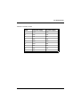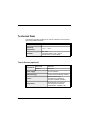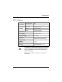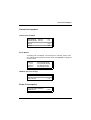
1
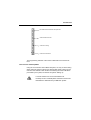
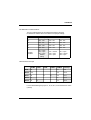
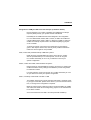
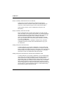
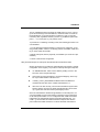
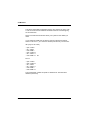
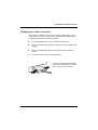
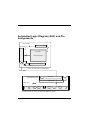
BA73A LCD TFT 15" (38.1 cm) Flat Screen User Manual Published by Wincor Nixdorf GmbH & Co. KG D-33094 Paderborn Bestell-Nr./Order No.: 01750038094A Printed in Singapore BA73A LCD TFT 15" Flat Screen User Manual Edition May 2001 MS-DOS®, Microsoft®, Windows 3.1 ®, Windows 95/98® Windows 2000®, Windows Me® and Windows NT® are registered trademarks of Microsoft Corporation, USA. PanelLink® is a registered trademark of Silicon Image Inc., USA Pentium® is a registered trademark of Intel Corp., USA PCI® is a registered trademark of the PCI Special Interest Group (SIG), USA BEETLE® is a registered trademark of the Wincor Nixdorf GmbH & Co. KG All other trademarks are the property of their respective owners Copyright © Wincor Nixdorf GmbH & Co, KG, 2001 The reproduction, transmission or use of this document or its contents is not permitted without express authority. Offenders will be liable for damages. All rights, including rights created by patent grant or registration of a utility model or design, are reserved. Delivery subject to availability; technical modifications possible. Contents Introduction ............................................................................................... 1 From Point-of-Sale to Point-of-Service ....................................................... 1 Advantages at a Glance.............................................................................. 2 Unpacking and checking the Delivery Unit ................................................. 3 About this Manual........................................................................................ 3 BA73A Components ................................................................................. 4 Screen Module ............................................................................................ 4 LCD-Controller -A/BA73A ........................................................................... 5 Capacative Touch Screen (Option) ......................................................... 8 General........................................................................................................ 8 Touch Screen and Sleep Mode.............................................................. 9 How to Operate ....................................................................................... 10 Cleaning Instructions .............................................................................. 10 COM Board for Touch Screen ............................................................... 10 I/O-Addresses of COM Interfaces ........................................................ 11 COM Interface Interrupts ...................................................................... 11 Assignment of COM port addresses and interrupts .............................. 13 IRQ9, conflict with powerfail interrupt of BEETLE systems ................. 13 IRQ10, conflict with COM3, COM4 of BEETLE systems ..................... 13 IRQ11, most likely conflict SCSI controller or USB .............................. 13 IRQ12, most likely conflict Mouse Port or PS/2 Mouse ....................... 14 IRQ15, most likely conflict IDE controller ............................................. 14 Adding COM ports under Windows NT ................................................ 14 Adding COM ports under Windows 9x, Windows Me and Win2000.... 14 Using shared interrupts for COM ports ................................................ 15 Using shared interrupts for COM ports under Windows 95 ................. 17 Using COM ports under Windows 3.x .................................................. 17 Using COM ports under MS-DOS ........................................................ 17 LCD-TFT Adapter A-Celeron/Pentium III ................................................ 19 Resistive Touch Screen (Option) ...........................................................20 General....................................................................................................20 How to Operate .......................................................................................21 Installing and Securing the Screen into Place .....................................23 Adjustable Screen Angle ...........................................................................25 Ergonomic Terminal Workplace ................................................................26 Installation ................................................................................................27 Installing the Controller in the BEETLE .....................................................27 Connecting the Speaker Cable ...............................................................29 Connecting the BA73A to the BEETLE /20 ...............................................30 Connecting the BA73A to the BEETLE /XL-II............................................30 Connecting the BA73A to the PC ..............................................................31 Connecting the BA73A to the BEETLE /M ................................................31 The Jumper layout of the Celeron/Pentium III “D2"- board.....................32 Jumper Setting ........................................................................................33 The Jumper layout of the Celeron/Pentium III “D1"- board.....................34 COM2 with Celeron/Pentium III Board (“D1"-CPU) ................................35 LCD Paneltype Settings for BA73A.........................................................35 Connecting the cable...............................................................................36 Installing a LCD-TFT Adapter A ................................................................37 Inserting the Cable.....................................................................................38 Releasing the Cable Connection ..............................................................39 Software Installation................................................................................40 Software Interfaces..................................................................................41 Touch Screen ............................................................................................41 Touch Screen and Sleep Mode...............................................................41 TFT LCD Flat Screen.................................................................................41 Automated Logic Diagram (ALD) and Pin Assignments ....................42 Interface .....................................................................................................43 Inverter (High-Voltage Generator) .............................................................43 Touch Screen and Controller.....................................................................43 Pin Assignments ........................................................................................44 COM 6 Interface of the LCD-Controller-A/BA73A...................................45 Internal Speaker Connector for Controller and BEETLE-CPU ...............45 COM7 and COM8 Interfaces of the LCD-Controller-A............................45 Internal Connecting Socket...................................................................46 External Connecting Socket..................................................................47 Technical Data ........................................................................................ 48 Touch Screen (optional)............................................................................ 48 TFT/ LCD Screen ...................................................................................... 49 BA73A ....................................................................................................... 50 Current Consumption ................................................................................ 51 LCD-Controller-A/BA73A ........................................................................ 51 Screen Module........................................................................................ 51 COM6/7/8 with Power Supply................................................................. 51 Power Consumption .................................................................................. 51 LCD-Controller-A/BA73A .......................................................................... 52 COM Board ............................................................................................... 53 Manufacturer’s Declaration and Approval............................................ 54 General Authorization ............................................................................... 54 FCC-Class A Declaration .......................................................................... 54 Tested Safety ............................................................................................ 55 User Information........................................................................................ 55 Safety Instructions..................................................................................... 56 Instructions for Maintenance ..................................................................... 57 Warranty .................................................................................................... 57 Recycling ................................................................................................... 57 Appendix ................................................................................................. 59 Abbreviation Index..................................................................................... 59 Introduction From Point-of-Sale to Point-of-Service “The customer is king”, a motto that seems so simple and yet it demands a permanently increasing supply of goods and services, both quantitatively and qualitatively. More customer service and more customer information have transformed the point-of-sale to a point-of-service, as business transactions are becoming more complex and there are growing demands on shop assistants and personnel working on the cash till. By using the BA73A you are provided with a terminal-orientated, ergonomical and customer-friendly cashier’s workplace. The BA73A is equipped with the PanelLinkTM technology with the new highlights: cable distance support up to 5m, flexible All-in-One cable for Touch Screen, loudspeaker and supply voltage. Optionally BA73A is equipped with a Touch Screen including a loudspeaker. The BA73A can be applied in all trade market segments like specialist retailers, department stores, self-service stores, petrol stations or in restaurants. There is indeed a great deal of scope for implementing the BA73A. They can be used, for example, as: n an ordering terminal n an information terminal n a lottery terminal n a point-of-sale terminal n a training terminal. GB - 1 Advantages The low-energy, flickerfree and radiation-free colour monitor of the BA73A is an Active-Matrix-Display in TFT-technology (Thin Film Transistor). Therefore, it is well suited for multimedia applications as it offers brilliant colour representation, an excellent contrast ratio and a high display speed. The screen can be installed directly on the cashier’s desk. Furthermore, it can also be set up on the central unit of a modular BEETLE system. Advantages Advantages at a Glance r r r r r r r r r r r r r r GB - 2 low footprint ergonomic terminal workplace; adjustable loudness and brightness Power Saving Mode basis for animation and multimedia flickerfree and free from radiation resolution XGA 1024 x 768 TFT-Technology, high luminiscence and high brightness very good contrast ratio Touch Version with Magnetic Swipe Card Reader or Chip Card Reader no need for LCD adjustments flexible All-in-One cable for touch function, LCD, PanelLink and supply voltage cable length for 3m up to 5m (16 foot) Digital Interface Delivery Unit Unpacking and checking the Delivery Unit Unpack the parts and check to see whether the delivery matches the information on the delivery note. The delivery comprises of the respective screen module. Controllers and data cables, necessary for operation, can be ordered separately. If damage has occurred during shipping or if the package contents do not match the delivery note, immediately inform your Wincor Nixdorf sales outlet. Transport the device only in its original packaging (to protect it against impact and shock). Delivery Unit About this Manual This manual informs you about everything you might need to know for the installation (software and hardware), the operation and the maintenance of your BA73A. Some parts of this book require familiarity and experience in working with operating systems and installation and configuration procedures. GB - 3 BA73A Components Screen Module The screen module represents the main unit of the BA73A. It comprises of a TFT-LCD colour screen, the TFT-interface and an inverter that generates the voltage for backlighting the screen. As an option the screens are available with Touch Screen including a loudspeaker. Behind the cover on the back of the BA73A you connect the cable. Remove the cable cover by pushing it in the direction of arrow (see picture) and then taking it off upwards. Back of the screen The TFT LCD flat screen is an XGA-compatible 15-inch flat screen which is absolutely flickerfree and free of radiation and has only a low heat emission. It is designed for a resolution of 1024 x 768 pixel. Application programs should be used with this resolution! However, a resolution of 640 x 480 pixel is possible. In graphics mode this resolution is used during the start of the BIOS or with MS-DOS etc. It is also used for instance during installation or when configuration problems occur (protected mode of Windows). The resolution 640 x 480 pixel is implemented through “stretching”. GB - 4 LCD-Controller-A/BA73A “Stretching” is only possible when a separate LCD controller or an adapter (“PanelLink-Bridge”) is used (“D1" Central Processing Unit with Celeron or Pentium III Processor). There is no ”stretching" with the “D2" CPU. If the display element is damaged and the liquid crystal solution leaks out onto your hands or clothing, please wash your hands or clothing immediately under running water for at least 15 minutes, using soap or alcohol. If the liquid comes into contact with your eyes, consult a medical doctor immediately. LCD-Controller -A/BA73A LCD-Controller-A/BA73A For the LCD display r the LCD-Controller-A/BA73A (PCI) is needed and for the optional Touch function r the COM board (ISA) is needed. Both boards have to be connected. The Controller and COM board need one slot with PCI and ISA interface. Thus, a display controller can be connected with every BEETLE /M, BEETLE /20, BEETLE /XL-II, and BEETLE /S. The LCD/TFT adapter A-Celeron can be used instead of the LCD-Controller-A/BA73A. GB - 5 LCD-Controller-A/BA73A The LCD-Controller-A/BA73A is a plug-in-controller with a PCI-interface. There are two connections for r r a 40-pin MDR connector with integrated COM5 output a 9-pin DSUB female (for COM6) COM5 and COM6 are only ready for operation when the optional COM board is used. The control data and data lines for the TFT LCD display are transmitted to the 50-pin MDR connector via hardware drivers and filters. The cable, which is linked up to the screen module, is connected to this MDR connector. The all-in-one cable length is up to 5 m. The COM5 interface signals (for the Touch Screen) and the loudspeaker signal are also on this connector. A loudspeaker cable connects the beeper of the CPU to the loudspeaker connector of the controller. Please refer to the chapter “Installation” for further information. The screen panel next to the MDR connector has a 9-pin DSUB socket connector, to which the COM6 interface is connected. This is the interface with the power supply. This socket is always installed, but it will only work with the Touch Screen version. Please find a description of the COM board on page 11. GB - 6 LCD-Controller-A/BA73A 6 1 40 2 9 1 5 Panel of LCD- Ccontroller-A/BA73A COM5/ COM6 1 4 Speaker Connector Jumper B3 B2 B1 BIOS BA73A Connector incl. COM5, LCD Interface and Loudspeaker MDR Connector (40-pin) COM6 resp. "Touch In" DSUB Socket (9-pin) Board layout (LCD-Controller-A/BA73A) Jumper Settings of the LCD-Controller-A/BA73A: B1: B2: B3: OPEN Closed Closed GB - 7 Capacative Touch Screen (Option) General The TFT Touch Screen works according to the principle of a change in analog capacitance. It has a glass screen with a transparent, thin-film overlay on the surface. This is fully sealed and protected by a further layer of clear glass. Electrodes on the edges of the screen provide a uniform low-voltage field. As soon as you touch the screen with your finger the contact point is “recognized” by the change in capacitance. Because this takes place very quickly - 15 milliseconds after being touched - the Touch Screen is optimally equipped for a number of different requirements and applications. GB - 8 Touch Screen Anti Reflective Etched Surface and protection ClearTek Glass Overcoat Conductive Coating Protective Noise Shield The programming interface of the screen is identical to the mouse interface. Touch Screen Touch Screen and Sleep Mode Using the Touch Screen with a BEETLE System, an entry via touch during sleep mode may lead to a faulty input. During sleep mode nothing can be read from the LCD flat screen. Entries via touching the screen will still be processed by the system, but without the system “waking up”. For these reasons it is not recommended to set the sleep mode. For details please read the manual “POSMotherboard” delivered with your BEETLE System. GB - 9 Touch Screen How to Operate The Touch Screen responds to the slightest contact, therefore you do not have to apply much pressure when working with the screen. This does not only safe time, but is also kind to your joints! Touching the touch glass has the same effect as clicking the left mouse button. You only need to apply a little pressure with the fingertip. In this capacitive process only fingertip contact is recognized. The screen does not react in any way if touched, for example, with a pencil or a glove. You can adjust the brightness and the loudness with the thumb wheels located down to the right of the front of the screen. Cleaning Instructions Always turn off the system before cleaning. The glass surface of your Touch Screen should be cleaned with a mild, commercially available glass cleaning product. All pH neutral materials (pH 6 to 8) are good for cleaning. Cleaners with pH values 9 to 10 are not recommended. Cleaning with water and isopropyl alcohol is possible as well. Do not use solvents containing acetic acid. Use a soft, fine-meshed cloth to clean the surface. Dampen the cloth slightly and then clean the screen. A wrong maintenance may cause damages to the screen, which are not covered by guarantee or warranty. COM Board for Touch Screen The COM Board is an additional board for the LCD-Controller-A with an ISA bus interface that has 2 or 4 COM interfaces (COM5, 6, 7, 8). COM5 and COM6 are linked to the BA72 controller via a plug connector. COM5 is a reduced COM interface for RxD and TxD signals and is intended for the use of the (optional) touch function. As an option the COM board can be equipped with a COM7 and a COM8 interface. These can alternatively be operated as power-supplied interfaces (COM7* /COM8*) or as powerless interfaces (COM7 / COM8). GB - 10 COM Board I/O-Addresses of COM Interfaces COM Board The four COM interfaces of the COM board have the following I/O-addresses. Please refer to the table for the jumper settings. COM Address (Hex) 5 2E0 - 2E7 330 - 337 320 - 327 6 328 - 32F 338 - 33F 328 - 32F 7 3E0 - 3E7 340 - 347 360 - 367 8 368 - 36 F 348 - 34F 368 - 36F Jumper Position IO1 = open IO2 = open IO3 = open Default setting IO1 = closed IO2 = open IO3 = open IO1 = open IO2 = closed IO3 = open COM Interface Interrupts COM5 COM6 COM7 COM7-8 COM6-8 Interrupt IRQ9 I9 - - - I11 IR9 IRQ10 I10 - - - I12 IR10 IRQ11 I5 - I4 I8 I13 IR11 IRQ12 I1 - - - I6 IR12 IRQ15 I3 I2 - - I14 IR15 For the default setting the jumper I1, I2, I8, IR11, IR12 and IR15 are active (closed). GB - 11 COM Board The interrupts IRQ9 and IRQ10 are added for PC application only. For a correct reproduction of the interrupt signals it is necessary that the jumper IR9 to IR15 are not activated. To activate the interrupt request signal the corresponding jumper must be closed. To avoid possible conflicts with already existing plug-in-boards in your system, deactivate those jumpers on the COM board, that are no longer needed (opening the jumpers). GB - 12 COM Board Assignment of COM port addresses and interrupts (installation details) Ensure that there is no conflict of hardware port addresses or interrupt requests (IRQs) used by your system and the COM Board! Essentially the AT COM Board has been designed to be configurable for a non-shared IRQ9, IRQ10, IRQ11, IRQ12, or IRQ15 for COM5 and a shared IRQ9, IRQ10, IRQ11, IRQ12, or IRQ15 for COM6,7,8 and even COM5. The interrupt requests have to be enabled explicitly by jumpers on the controller. To assist you further, some hints to the assignment of interrupts are given in this chapter. Please note, that only some possible conflicts are mentioned. There might be more possible! IRQ9, conflict with powerfail interrupt of BEETLE systems IRQ9 cannot be used with BEETLE systems, since this is in conflict with the powerfail interrupt. For other systems, no hint can be given for a conflict that is likely to occur. So you will have to check your specific configuration. IRQ10, conflict with COM3, COM4 of BEETLE systems IRQ10 cannot be used with BEETLE systems, since this is in conflict with COM3 and COM4. Factory settings of the BEETLE provide using IRQ10 for COM3 and COM4. For other systems, no hint can be given for a conflict that is likely to occur. So you will have to check your specific configuration. IRQ11, most likely conflict SCSI controller or USB The Adaptec product line of SCSI controllers uses IRQ11 as default. If this is your type of controller, please check. Refer to your technical documentation, if a change of the configuration is required. BEETLE systems factory settings provide to use shared IRQ10 for COM3 and COM4, but COM4 can be configured by jumpers on the motherboard to use IRQ11 instead. Some of the latest PCs use IRQ11 for USB (Universal Serial Bus). GB - 13 COM Board IRQ12, most likely conflict Mouse Port or PS/2 Mouse These types of mice are supported by Windows NT through the I8042PRT.SYS driver. The mouse usually has a (small) cylindric 6 pin connector. It seems that these types of mice mostly will use IRQ12. Some systems, however, allow to disable the mouse port in the BIOS Setup. IRQ15, most likely conflict IDE controller Many motherboards of the Pentium class dispose of an IDE controller, which uses IRQ14 for the primary IDE controller (1st channel) and IRQ15 for the secondary IDE controller (2nd channel). A conflict may arise with the IRQ15 if the secondary IDE is set to “enabled” in the BIOS setup, e.g. because the BEETLE system is equipped with a CD ROM drive. Thus the IRQ15 can not be used by other controllers or functions, e.g. by an AT COM board. If the secondary IDE is set to “disabled” in the BIOS setup, the IRQ15 is available and can be used by other controllers/functions, e.g. by an AT COM board. Adding COM ports under Windows NT To add a COM port to your system configuration, run the Control Panel from the Program Manager. Click on the Ports icon and then on the Add button to make a new COM port known to the system. Then enter IRQ and hardware address according to the jumper configuration you set before. See sections 3 and 4 for details about setting the jumpers. Adding COM ports under Windows 9x, Windows Me and Windows 2000 To add a COM port to your system configuration, run the “Add New Hardware” wizard. It is not recommendable to run the automatic hardware detection! Add the new COM port explicitly instead. It would get some (presumably wrong) port address and IRQ. Change these according to the jumper configuration you set before. See the sections 3 and 4 for details about setting the jumpers. After having made these changes to the Windows 9x configuration, you will have to reboot the system, before they can get into effect. It is not recommended, however, to reboot before having entered the port address and IRQ correctly. GB - 14 COM Board The AT COM Board manual numbers the COM ports from 5 to 8. The origin of this numbering is from the BEETLE, which has COM1 to COM4 on the motherboard. It is recommended for consistency, that you use this numbering also, regardless whether you have e.g. a BEETLE (with COM ports 1,...,4) or a PC (with e.g. only COM1 and 2). To provide for a numbering according to that, the following procedure is recommendable: 1. run the Add New Hardware wizard to configure new COM ports, so adding possibly COM3, COM4, if not already present and COM5, COM6 and (if you have) COM7 and COM8 2. delete COM ports, that are physically not available (i.e. served as a placeholder) 4. reboot to activate the configuration Using shared interrupts for COM ports with Windows NT and Windows 2000 Sharing an interrupt for a COM port under Windows NT requires a specific configuration in the Registry. To provide for interrupt sharing the steps are: r r r r run REGEDT32.EXE, which can be called by clicking on Run in the File menu of the Program Manager assure that you have permission to change the Registry, which maybe only an administrator is allowed to do in HKEY_LOCAL_MACHINE\SYSTEM\CurrentControlSet\Services\Serial set the value of the variable ‘PermitShare’ to 1 take care to do this correctly, since the documentation says that bad Registry entries may have the result that Windows NT cannot come up; a good idea could be to backup the Registry before. Since the ‘PermitShare’ variable has global effect on all COM ports, it is your responsibility to ensure that sharing of interrupts can be performed on all COM ports installed. In a PC configuration with COM1 and COM2 integrated in the motherboard chipset using IRQ4 and IRQ3 rsp., you could e. g. have the idea to install another ISA multiport card with two ports COM3 and COM4 and wish to run them with IRQ4 and IRQ3 too. GB - 15 COM Board This will be impossible for hardware reasons! The problem is, that in such a case on the AT bus two different hardware instances would be fighting for the same IRQ! Refer to the technical information about your system for the details you need! If you configured COM ports to share a common interrupt and ‘Permit Share’ is not set to 1, you could use all COM ports but only one at a time. like (only one at a time) - open COM n - use COM n - close COM n - open COM n+1 - use COM n+1 - close COM n+1 etc. but not - open COM n - open COM n+1 - use COM n - use COM n+1 - close COM n - close COM n+1 The ‘PermitShare’ variable is specific to Windows NT. Windows 95 is different (see below). GB - 16 COM Board Using shared interrupts for COM ports under Windows 95 Under Windows 95, sharing COM ports doesn’t require special provisions other than correctly specifying the resources used in the Device Manager. However, in addition to avoid port address conflicts, you must ensure that no two different pieces of hardware on the AT bus are fighting for the same IRQ! Using COM ports under Windows 3.x Windows 3.x does not allow interrupt sharing! Windows 3.x only allows for using 4 COM ports! Using COM ports under MS-DOS Interrupt support for COM ports isn’t provided at all by the operating system. So, it is the responsibility of the application program provider to provide for interrupt support, as e.g. RDI drivers do. However, in addition to avoid port address conflicts, you must ensure that no two different pieces of hardware on the AT bus are fighting for the same IRQ! GB - 17 COM Board Interrupt Jumper IO Jumper IO 1 IO 3 I9 I 1 I 16 I8 Interrupt Request IR 9 IR11 IR15 IR10 IR12 COM 5 / COM 6 21 COM7 2 1 COM8 Board layout COM board GB - 18 LCD-TFT Adapter A-Celeron LCD-TFT Adapter A-Celeron/Pentium III LCD-TFT Adapter A-Celeron If your BEETLE is equipped with a “D1" or ”D2" CPU the TFT adapter can be connected with the CPU without LCD-Controller-A and without COM board. The LCD TFT adapter-A is a submodule of the CPU which is necessary for the connecting process. The optional touch function is to be realized internally via the COM2 interface. When applicating the touch function the COM2 interface (D-sub connector on the motherboard) cannot be used. For further information please read chapter “Installation, connecting the TFT to a BEETLE /M”. TFT adapter The TFT adapter can optionally be connected to a 40-pin MDR connector for the touch screen and the LCD. 2 40 1 Cover of the adapter GB - 19 Resistive Touch Screen (Option) General The resistive TFT Touch Screen is constructed of a hard-coated polyester topsheet that is overlaid on a conductively-coated glass layer. Voltage is applied to the topsheet. As the user touches the screen, the topsheet compresses into contact with the glass layer, and current flows to the four corners in proportion to the distance from the edge. The controller then calculates the position of the finger or stylus, based on the current flow. Because the controller derives both the “X” and “Y” touch coordinates from the stable glass layer, the accuracy and operation of the touch screen is unaffected by damage to the topsheet caused by extended use or neglect. GB - 20 Construction of the resistive Touch Screen: Hard-coated polyester topsheet Adhesive Glass substrate with spacer dots How to Operate Touching the touch screen has the same effect as clicking the left mouse button. You only need to apply a little pressure with the fingertip. In this resistive process not only fingertip contact is recognized. The screen does react in any way if touched, for example, with a stylus. The recommended material for a stylus is polyacetal. The stylus should have a minimum spherical radius of 0.8 mm and contain no sharp edges or burrs that may cause damage to the topsheet. You can adjust the brightness and the loudness with the thumb wheels located down to the right of the front of the screen. GB - 21 Cleaning Instructions Always turn off the system before cleaning. The surface of your Touch Screen should be cleaned with a water-based solvent or a non-abrasive cleaner.Do not use solvents containing acetic acid or methylene chloride. Use a soft, fine-meshed cloth to clean the surface. Dampen the cloth slightly and then clean the screen. GB - 22 Installing and Securing the Screen into Place The screen can be easily installed as a table top terminal. Securing into Place Remove the footed stand and screen element from the cardboard packaging. Tilt the screen backwards. Turn the fastening screw on the screen with a crosstip screwdriver until the connecting part is loosened. Then insert it into the footed stand. Insert the joint of the screen element into the footed stand. GB - 23 Securing into Place Now fasten the screw on the footed stand into place again using the crosstip screwdriver. Ensure that the screw is in the correct position. GB - 24 Adjustable Screen Angle Adjustable Screen Angle Adjustable Screen Angle The BA73A is fitted with a joint on the rear. You can optimize the angle of the screen depending on the viewing and lighting conditions. loose tight Use a screwdriver to set the twisting force of the BA73A on the adjusting nut. 90 0 The angle of the screen can be adjusted from a horizontal position to a vertical position to the stop (max. 90°), without any tools. GB - 25 Ergonomic Terminal Workplace Ergonomic Terminal Workplace Ergonomic Terminal Workplace Please observe the following when setting up your terminal workplace: Avoid direct glaring and reflective glaring. Use the screen only in a controlled luminance surounding. Install the device with a viewing direction that is parallel to the windows. Avoid reflective glaring caused by electric light sources. Permitted range of vision 0° 40° 30° 30° GB - 26 Position the screen within a preferred and permitted range of vision, so that you can look vertically onto the screen. Installation Installing the Controller in the BEETLE First ensure that the controller is switched off and the mains supply plug has been pulled out. Remove the housing upwards. Take care in doing so that you do not tilt or jam the housing in any way. If a VGA sandwich module or a VGA controller is installed, remove this board. Mind the measures of electrostatically endangered components. Note! Remove the VGA sandwich module or if necessary the VGA controller! GB - 27 Installing the Controller in the BEETLE Metal tracks Speaker connector In order to be able to install the LCD-Controller-A, you must first remove the metal panel that covers the free slots by loosening the screw. Set the jumper for the I/O addresses and the interrupt requests on the COM board. It is strictly necessary to avoid conflicts, so please inform yourself of already existing settings. Plug the TFT COM board into the corresponding ISA terminal and plug the LCD-Controller-A into the PCI terminal. Connect the COM/5 and COM/6 interfaces of the COM board with the LCD-Controller-A. Push the plastic cramp horizontally into the LCD-Controller (1) and into the COM (2) board at the same time. ➊ Secure the controller into place by retightening the screw. Installing the Controller in the BEETLE ➋ GB - 28 Connecting the Speaker Cable Connecting the Speaker Cable Connecting the Speaker Cable Remove the speaker cable from the BEETLE-CPU by simply unplugging the connector. The BEETLE speaker is then inactive. The 4-pin plug connector is next to the RAM module. Use the TFT speaker cable (delivered with the system) to connect the 4-pin-plug connector of the LCD-Controller-A with the 4-pin plug connector of the BEETLE-CPU. LCD-Controller COM Board BEETLE CPU Connecting the speaker cable If you do not connect the BA73A to a BEETLE-CPU but to another commercially available PC, please pay attention to the pin assignment of the speaker. A loudspeaker cable for a PC is not included in the delivery unit. GB - 29 Connecting the BA73A to the BEETLE /20 Connecting the BA73A to the BEETLE /20 The hardware installation is carried out according to the installation of the BA73A to the BEETLE. When installing the LCD-Controller, you have optionally two further COM interfaces (COM7 and COM8) at your disposal. Ccontroller COM6 COM8 COM7 AT-SLOT Unterdose Netzspannung LAN DC24 KYBD CASHDR COM4* COM3* COM2* LPT1 COM1 VGA/LAN/ASYN Back of the BEETLE /20 Connecting the BA73A to the BEETLE /20 Connecting the BA73A to the BEETLE /XL-II Connection of the BA73A to a BEETLE /XL-II via the TFT-LCD Adapter A. Adapter ON 110-120 V / 2 A max 200-240 V / 1 A max DC24V 1 2 Cashdr. Only CRT/TFT LPT1 MIC KYBD COM4 Back of the BEETLE /XL-II GB - 30 COM3 USB COM2 COM1 LAN SPK Connecting the BA73A to the PC Connecting the BA73A to the PC Connecting the BA73A to the PC First ensure that the controller is switched off and the mains supply plug has been pulled out. Then loosen the housing of the PC and unscrew the panel. Take care in doing so that you do not tilt or jam the housing in any way. For the connection to a PC please refer to the documentation delivered with your PC. Use a free PCI/ISA slot for plug in the LCD-Controller-A (PCI) and the COM board (ISA). Ensure that the jumpers are set correctly. The interrupts IRQ9 and IRQ10 are provided for PC applications. See also the chapter “Controller”. When connecting the BA73A to a standard PC observe the compatibility by tests. The LCD controller with “Touch in” is installed in PC that provide only PCI slots. A COM interface of the PC is used for the touch function. It is connected to the COM interface of the controller via a separate cable. An Installation Instruction is delivered with the Wincor Nixdorf Order Unit “PC Cable Set”. Connecting the BA73A to the BEETLE /M With a BEETLE /M containing a Celeron/Pentium III-CPU a LCD TFT Adapter-A can be installed instead of a LCD-Controller-A. The adapter is installed ex works. If you want to upgrade your BEETLE /M later, please read the section “Installing the TFT adapter" at the end of this chapter. If a TFT adapter-A is installed, a BA73A can be connected to the BEETLE /M without assigning a slot. The connection of the adapter and the display and the loudspeaker is effected via a 40-pin data cable. The signals for the touch screen function and the source are effected via this cable as well. Before installing the display by using of the touch screen function please note the following aspects: r The internal loudspeaker has to be pulled off in order to activate the loudspeaker on the screen display. GB - 31 Jumper Layout r r The touch function with a LCD TFT adapter-A has to be activated via a jumper. The COM2 interface has to be covered and may no longer be used externally. The Jumper layout of the Celeron/Pentium III “D2"- board Jumper Layout GB - 32 Jumper Layout Jumper Setting One jumper of the PT-jumpers is used to define the size of the TFT monitor: 12" and 15". 1 12" monitor connected 1 15" monitor connected The second and the third jumper are reserved for future applications. GB - 33 Jumper Layout The Jumper layout of the Celeron/Pentium III “D1"- board NVR PS2/Mouse 32KB or 128KB 512KB XILINX BIOS MEMC 49F002T NV-RAM KYB/E PROG PWON MIC COM4* SuperI/O PC97317 COM3* FD/F FD AD1816AJS I2C PCI/ISA 16 - y + PCI-ONBOARD COM2*/I S1 S2 VGA/CRT COM2* COM1 IDE2 IRQ I PT 1 POW1 LPT POW2 USB WOLN IDE1 CELERON 82443BX CD-AUDIO VGA/TFT SP AUDIO LED 69000 DIMM0 DIMM1 GB - 34 LM80 Max1617 L12V L5V OUT Jumper Layout COM2 with Celeron/Pentium III Board (“D1"-CPU) r COM2 for peripherals 1 S1 r S2 COM2 for touch function ussing a TFT adapter 1 S1 S2 If the BEETLE is delivered with TFT adapter with touch function, the jumper is already set ex works. After having set the necessary settings on S1, S2 and S3 in the case of using the touch function, continue according the following instructions. LCD Paneltype Settings for BA73A Paneltype 0: XGA (1024 x 768), set ex works. Interrupt Paneltype reserved 1 I 1 I 2 I 3 P T 4 P T 3 P P T T 2 1 GB - 35 Connecting Cable Connecting the cable The data cable is to be connected with the 50-pin connector of the TFT adapter. Take care that the thickening of the cable (Ferrit) is principally positioned on the side of the TFT adapter. Connecting Cable Battery COM7 COM8 ON 110-120 V / 2 A max 200-240 V / 1 A max DC24V KYBD 1 COM4 2 LPT1 COM3 Back of BEETLE /M system USB COM2 COM1 LAN/ASYN TFT-Adapter The connecting socket of the LCD-module is situated below the cover. The cover can be released by pressing smoothly in direction of the arrow. Tilt up the cover and release it. When doing so please take care of the anchorage. GB - 36 TFT adapter Now plug in the cable until it snaps in (see illustration). When removing the cable press on the connector release. Installing a LCD-TFT Adapter A Never open the BEETLE when the circuit is switched on. Plug in the TFT adapter on the CPU module via the sub module as shown in the illustration. TFT adapter Submodul GB - 37 Inserting the Cable Inserting the Cable Inserting the Cable The cable cover is located in the base plate. PULL Lift the cable cover . Pull the cable cover forward in the direction of the arrow , and then remove it from the guide rail. PULL PULL GB - 38 Insert the 40-pin BA73A cable of the keyboard. The cable will be carried in a curve from the small cover of the screen module to the cable cover. Replace the cable cover in the guide rail. Pay attention to the openings. Slide the cable cover back into place. When you hear a click, the cover is locked into place. Releasing the Cable Connection Releasing the Cable Connection Releasing the Cable Connection Never remove a cable from a connector socket by simply pulling on the cable. Always remove the cable by the connector housing. Please follow the instructions below when removing cables: r r r r Turn off all switches to the mains and electrical equipment. Remove all mains cables from the shockproof sockets installed in the building. Remove all datatransfer cables from the data network connector devices. Loosen all cables on the electrical equipment. Press the metal latches of the MDR connector together and then remove the connector from the socket. GB - 39 Software Installation The software installation refers to the installation of corresponding display drivers; the installation of the touch screen comprises the allocation of resources for the COM interfaces, too. For this, corresponding diskettes are delivered with the system. The installation of display drivers is normally done after a VGA card is replaced with the TFT controller. As these normally need different drivers, it is highly recommended to set the standard VGA mode (resolution 640 x 480 pixel, 16 colours) before installing the controller. At any rate you should check, whether the file CONFIG.SYS contains an entry for a store manager (like e.g. EMM386.EXE). This entry must take into account the necessary cluster of 40 KB for the "D1" Motherboard (segment address C000-C9FF) for the BIOS of the TFT controller, resp. 48 KB (segment address C000-CBFF) for the "D2" Motherboard. Entry for "D1" Motherboard: DEVICE= C:\WINDOWS\EMM386.EXE X=C000-C9FF NOEMS Entry for "D2" Motherboard: DEVICE= C:\WINDOWS\EMM386.EXE X=C000-CBFF NOEMS When installing the touch screen software and resource allocation (I/O address; interrupt) for the COM interfaces, mind the following: During the installation there may be conflicts concerning the I/O addresses and the interrupts. So inform yourself of the resources already allocated and read the instructions in the files, e.g. readme file, of the installation diskettes very carefully. Then you can allocate the resources and set the corresponding jumper configuration on the COM board. The BA73A is supported by the operating systems MS DOS; Windows 98, Windows 2000, Windows Me and Windows NT. The hardware interfaces and the firm-ware interfaces of the display are open. Now it is possible to develop drivers, e.g. for other operating systems, by software companies. GB - 40 Software Interfaces Touch Screen Touching the screen corresponds to press the left mouse key. The touch screen programming interface is identical to that of the mouse interface. Touch Screen and Sleep Mode Using the Touch Screen with a BEETLE Pentium CPU, an entry via touch during sleep mode may lead to a faulty input. During sleep mode nothing can be read from the LCD flat screen. Entries via touching the screen will still be processed by the system, but without the system “waking up”. For these reasons it is not recommended to set the sleep mode. For details please read the manual “POS Motherboard", delivered with your BEETLE. TFT LCD Flat Screen The TFT LCD flat screen is XGA-compatible. The LCD controller of the TFT is a Chips & Technologies, 69000 B module. The resolution of the TFT LCD flat screen is 1024 x 768 Pixel (XGA mode). GB - 41 Automated Logic Diagram (ALD) and Pin Assignments Bildschirmm Screen module Inverter for two Backlights 7 TFT-Interface 4 TFT-Display 31 Touch Screen (Option) 2 Touch Screen Controller (Option) Loudspeaker (Option) Signals: TFT-PLINK, COM5, Loudspeaker (Option) 40pin. MDR LCD-Controller-A (PCI Interface) COM Board (ISA Interface) 40pin MDR COM8* FREE ISA-Slot COM7* COM6 BEETLE-CPU 1 CASHDR MIC KYBD COM4 COM3 USB COM2 COM1 * The interfaces COM 7 and COM 8 are available with BEETLE /20 and /M GB - 42 LAN SPK Automated Logic Diagram Interface Automated Logic Diagram The LCD interface is connected to the TFT controller via a 40-pin cable. The inverter, LCD display, touch screen controller and beeper are connected to this interface in the TFT screen module. Inverter (High-Voltage Generator) Inside the TFT, the high voltage needed for backlighting the LCD display is generated by the inverter! High Voltage! Before opening the device, make sure, that the device is disconnected from the main power supply. Opening of the device only by authorized personnel! Touch Screen and Controller An analog capacitive or an analog resistive touch screen is connected. The touch screen controller has an RS232 interface. GB - 43 Pin Assignment Pin Assignments BA73A Connectors of the 40-pin TFT Interface GB - 44 Pin Assignment PIN # Signal PIN # Signal 1 HUOUT 2 RXCN 3 GND 4 RXCP 5 P5VLCD 6 P5VLCD 7 RX0N 8 GND 9 RX0P 10 FPEN 11 RxD1 12 GND 13 TxD1 14 P12VLCD 15 GND 16 P12VLCD 17 GND 18 RXIN 19 GND 20 RXIP 21 GND 22 P12VLCD 23 RX2N 24 GND 25 RX2P 26 GND 27 NC 28 NC 29 NC 30 NC 31 NC 32 NC 33 NC 34 NC 35 NC 36 NC 37 NC 38 NC 39 NC 40 NC Pin Assignments COM 6 Interface of the LCD-Controller-A/BA73A PIN # signal 1 P12VF 2 RxD2 3 TxD2 4 DTR2 5 GNDF1 6 DSR2 7 RTS2 8 CTS2 9 P5VF Internal Speaker Connector for Controller and BEETLE-CPU PIN # signal 1 n.c. 2 n.c. 3 n.c. 4 HUIN COM7 and COM8 Interfaces of the LCD-Controller-A Pin Assignments These plug connectors are available only for the BEETLE /M and BEETLE/20. Each connector is plugged into a 2x7 PIN connector, to which either a 9-pin DSUB socket (COM interface with power supply) or a 9-pin DSUB pin terminal (COM interface without power supply) are connected. The DSUB connector housings are screwed onto the BEETLE housing. GB - 45 Pin Assignments Internal Connecting Socket GB - 46 PIN# COM7 COM8 1 P5VF P5VF 2 GNDF GNDF 3 DCD3 DCD4 4 GND GND 5 CTS3 CTS4 6 DTR3 DTR4 7 RTS3 RTS4 8 TxD3 TxD4 9 DSR3 DSR4 10 RxD3 RxD4 11 RI3 RI4 12 GND GND 13 P12VF P12VF 14 GNDF GNDF Pin Assignments External Connecting Socket PIN# with power supply w/o power supply 1 +12V DCD 2 RxD RxD 3 TxD TxD 4 DTR DTR 5 GND GND 6 DSR DSR 7 RTS RTS 8 CTS CTS 9 +5V RI GB - 47 Technical Data The following operating conditions are valid for a BA73A TFT that is fitted with all the available modules. Climate class IEC 721 3/3 Class 3K3 Operating temperature +5° C - + 40° C Humidity 5% - 85% Absolute humidity 1g/m³ - 25g/m³ Condensation is not permitted Touch Screen (optional) Resolutions GB - 48 Horizontal 999 pixel Vertical 999 pixel Power supply 5V from interface LCD technology Analog capacitive/analog resistive Surface Glass protective layer, anti-reflection (capacative); Polyester topsheet (resistive) Data transfer Bi-directional, asynchronous, Xon-Xoff protocol, RS 232, COM5/COM2, 2400 Bd, 8 bit TFT/LCD Screen TFT/ LCD Screen TFT/LCD Screen Frequencies Solutions Horizontal (KHz) 48.3 Vertical (Hz) 60 Horizontal 1024 pixel (XGA) Vertical 768 lines (XGA) Colour RGB 16, 256, 64k Pixel Format 0.30 mm x 0.30 mm Power Supply 5V from interface LCD Technology TFT, 18 Bit Brightness BA73A (with/ w/o Touch) approx. 190/230 cd/m2 (Center LCD) Reading Angle right/left top/bottom Backlight +/- 70° +/- 25 ° Twin lamps CCFL, Inverter Life time: 50 000 h The backlight is a wearing part and therefore not part of the warranty engagement or part of a possible service agreement. Only trained technical personnell is authorized to replace the backlight. Dispose of the backlight according to the regulations of your country. GB - 49 BA73A BA73A Dimensions Weight Screen size 15" (38.1 cm) Active screen size (horizontal x vertical) 304.1mm x 228.1mm Cable length 3 m / 5m Dimension Display Housing without foot. Stand/Hinge (W x H X D in mm) 390 x 305 x 57 Dimension Display Housing with foot. Stand/Hinge (W x H X D in mm) 390 x 355 x 200 Footed Stand (W x D) 280 x 190 incl. Footed Stand approx. 7.6 kg Footed Stand approx. 2.4 kg BA73A GB - 50 Current Consumption Current Consumption Current Consumption LCD-Controller-A/BA73A Normal Mode: 400 mA Standby Mode: 300 mA + 5V + 5V 50 mA +12V 30 mA -12V Screen Module Consisting of an LCD display, Touch Screen incl. controller, inverter, interface. Please check whether the system offers enough power to supply the screen module. 820 mA 0 mA 1000 mA 300 mA +12V (Normal Mode) +12V (Standby Mode) +5V (Normal Mode) +5V (Standby Mode) COM6/7/8 with Power Supply max. 900 mA + 12V max. 300 mA + 5V Power Consumption LCD-Controller-A/BA73A / COM Board: 2.5 W GB - 51 LCD-Controller-A/BA73A LCD-Controller-A/BA73A Interface PCI, 32 Bit Mode XGA Resolution 1024 x 768 (High Color) Image Repeat Memory 2 MB Screen Memory Text mode Page mode Linear mode B800H- BFFFH A000H- AFFFH according PCI BIOS 40 kB, Address C000H-C9FFFH Connections 1) 40-pin MDR connector for LCD interface, touch screen and loudspeaker 2) 9-pin socket for COM6, if COM Board exists TFT cable 40-pin connector, EMC protected Power Consumption 2.5 W Current Consumption 5V ±12V 370 mA, 50 mA / 30 mA LCD-Controller-A/BA73A GB - 52 COM-Board COM Board COM-Board Controller System interface ISA, 8 MHz I/O-addresses for COM interfaces 3 address records 2E0, 330, 320 that can be set by jumper Interrupts for COM interfaces IRQ11, IRQ12, IRQ15 can be set by jumper, IRQ9 and IRQ10 are for PC applications COM5 reduced COM interface, internal connection to the TFT controller (only TxD, RxD) COM6 RS232 with power supply 5V/12V internal connection to the TFT controller COM7 and COM8 (optional) Connection for COM7/8 and COM7*/8* Interface for BEETLE /XL , /M and /20, PC standard or Wincor Nixdorf retail standard with connector adapter for 9pin DSUB connector or socket GB - 53 Manufacturer’s Declaration and Approval General Authorization This device fulfills the requirements of the EEC standard 89/336/EWG “Electromagnetic Compatibility”. Therefore, you will find the CE mark on the device or packaging. FCC-Class A Declaration This equipment has been tested and found to comply with the limits for a Class A digital device, pursuant to part 15 of the FCC Rules. These limits are designed to provide reasonable protection against harmful interference when the equipment is operated in a commercial environment. This equipment generates, uses, and can radiate radio frequency energy and, if not installed and used in accordance with the instruction manual, may cause harmful interference to radio communications. Operation of this equipment in a residential area is likely to cause harmful interference in which case the user will be required to correct the interference at his own expense. Le présent appareil numérique n’émet pas de bruits radioélectriques dépassant les limites applicable aux appareils numériques de la “Class A” prescrites dans le Règlement sur le brouillage radioélectrique édicté par le ministère des Communications du Canada. GB - 54 User Information Tested Safety geprüfte Sicherheit The BA73A has been awarded the GS symbol for “Geprüfte Sicherheit” (tested safety). BA73A fulfills the requirements for ergonomy according to ISO 13406-2. Additionally, the BA73A has been awarded the cUL- and UL- symbol. n User Information Wincor Nixdorf GmbH & Co. KG (WN) does not accept responsibility for radio and TV interference and faults that are caused by unauthorized changes that have been made to the devices. Furthermore, cables or other devices that have not been approved by WN may not be connected to the device. The user is responsible for any faults and interference that are caused as a result. Repair work on the devices should only be carried out by authorized and specially trained personnel. Improper repairs will lead to the loss of any guarantee and liability claims. Extension boards with electrostatically endangered components can be identified with this label. Accessory LCD monitor BA73A for use with UL-listed Computers. User Information GB - 55 Safety Instructions Safety Instructions This device conforms to the corresponding safety regulations for information technology devices, including electronic office machines for use in the office environment. r Safety Instructions r r r r r r r GB - 56 If the device is moved from a cold environment to a warmer room where it is to be operated, condensation could occur. The device must be completely dry before being put into operation. Therefore an acclimatization time of at least two hours should be accounted for. Lay all cables and supply lines so that nobody can tread on them or trip over them. Data cables should neither be connected nor removed during electrical storms. Protect the device from vibrations, dust, moisture and heat, and only transport the device in its original packaging (to protect it against impact and blows). Take care to ensure that no foreign objects (e.g. paper clips) or liquids can get into the inside of the device, as this could cause electrical shocks or short circuits. In case of emergencies (e.g. damaged housing, liquid or foreign objects getting into the device), the device should be switched off immediately, the mains plug of the BEETLE or PC should be removed, and the Wincor Nixdorf customer service should be contacted. If the LCD display element is broken and the liquid crystal solution leaks out of the display and onto your hands, clothing etc, wash your hands or clothing immediately with soap or alcohol, holding them under running water for at least 15 minutes. If the liquid comes into contact with your eyes, please consult a medical doctor immediately. Generally you should connect IT-devices only to power supply systems with separately guided protective earth conductor (PE), known as TN-S networks. Do not use PEN conductors! Please also observe the recommendations of the norm DIN VDE 0100, part 540, Appendix C2, as well as EN50174-2, §5.4.3. Instructions for Maintenance Instructions for Maintenance Instructions for Maintenance Clean your BA73A regularly with an appropriate surface cleaning product. Make sure that the device is switched off, connector cables are unplugged and that no moisture is allowed to get into the inside of the device. Please observe the maintenance and cleaning instructions for each of the BA73A components. These instructions can be found in their respective chapters. Warranty Wincor Nixdorf guarantees a limited warranty engagement for 12 months beginning with the date of delivery. This warranty engagement covers all those damages which occur despite a normal use of the product. Damages because of r r r improper or insufficient maintenance, improper use of the product or unauthorized modifications of the product, inadequate location or surroundings will not be covered by the warranty. All parts of the product which are subject to wear and tear (e.g. backlight of the LED) are not included in the warranty engagement. Please order spare parts at the Wincor Nixdorf customer service. Recycling Environmental protection does not begin when the time has come to dispose of the BA73A; it begins with the manufacturer. This product was designed according to our internal norm “Environmental conscious product design and development”. GB - 57 Recycling The BA73A is manufactured without the use of CFCs und CCHS and is produced mainly from reusable components and materials. The processed plastics can, for the most part, be recycled. Even the precious metals can be recovered, thus saving energy und costly raw materials. Please do not stick labels onto plastic case parts. This would help us to re-use components and material. You can protect our environment by only switching on your equipment when it is actually needed. If possible, even avoid the stand-by-mode as this wastes energy, too. Also switch your equipment off when you take a longer break or finish your work. At the present time, there are still some parts that are not reusable. Wincor Nixdorf guarantees the environmentally safe disposal of these parts in a Recycling Center, which is certified pursuant to ISO 9001. So don’t simply throw your BA73A on the scrap heap when it has served its time, but take advantage of the environmentally smart up-to-date recycling methods! Please contact your competent branch for information on how to return and re-use devices and disposible materials. Recycling GB - 58 Appendix Abbreviation Index ASCII AT BIOS CFL COM CPU CRT DSTN H HW ISA ISO LAN LPT LCD MDR POS RAM SMD STN SVGA SW TFT UART XGA American Standard Code for Information Interchange Advanced Technology Basic Input Output System Cold cathode Fluorescent Lamp Communication Port Central Processing Unit Cathode Ray Tube Double Super Twisted Nematic, LCD Technology Hexadecimal Value Hardware Industrial Standard Architecture International Standards Organisation Local Area Network Line Printer Liquid Crystal Display Mini Delta Ribbon Point of Sale/ Point of Service Random Access Memory Surface Mounted Device Super Twisted Nematic, LCD Technology Super Video Graphic Array Software Thin Film Transistor Technology Universal Asynchronous Receiver/Transmitter Extended Graphic Array GB - 59