1
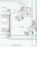
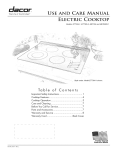
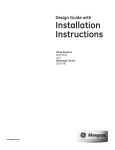
Installation
Instructions
If you have questions,
ca!l 800.626,2000
or visit our website at: ww.monogram.com
Wine Reserve
ZDWT240
and
Beverage Center
ZDBT240
DesignGuide
With InstallationInstructions
Monogram:
Safety Information
BEFORE YOU BEGIN:
WARNINGS:
Read
• Use
these
instructions
completely
IMPORTANT
for
local
inspector's
and
Note
to Installer
cords
use.
with
(-)wner's
- Be sure to leaxe these
the
- Keep
Manual
these
for flmue
gmtmded.
appareil
Consulter
lf)ou
&fit
<<Mise
recei',ed
center,
you
or builder.
See
_tre
with
instructions
pore"
page
replace
frayed
trait
heft)re
be
its intended
pm])ose.
electrical
service
or damaged.
cleaning
made
or making
by a qualified
repairs.
service
installation
Installation
Product
covered
taihu'e
trader
the
due
• I,es
basic
to improper
GE Appliance
dealer
mechanical
responsibility
le bar
of the
ou
r_i_arations
technicien
your
requires
is the
_'l la terre.
4.
or beverage
pour
l'usage
remplacer
imm&liatement
_lectrique
tout
efliloch_
ou
endommag¢:.
le nettoyage
contact
ou
que
:
construit.
d'alimentation
• D_brancher
reserxe
cet appareil
il a _t_
r_parer
cordon
4.
utiliser
lequel
• I1 taut
raise
page
wine
immediately
-
Proper
correctement
a damaged
should
skills.
is not
become
the
• ll ne taut
reference.
"(;rom_dinf',
_'l la terre>>,
Skill Level
installer.
for
or
AVERTISSEMENT
Consumer.
AVERTISSEMENT
Cet
only
repair
• ]_epairs
should
technician.
WARNING - his li ,nre.st
e be
properly
appliance
that
• Uni_lug
- Obse,,e _,ll_.,eH_ing
to Consumer
xour
this
• Immediately
ordinances.
instructions
Note
carefully,
- S_,,e_heseinst,uctions
IMPORTANT
codes
and
ou
route
le r_fl'ig_rateur
a vin
a\m_t
intervention.
doivent
_tre
taites
par
tm
qualifi_.
For Monogrmn
1.800.444.1845
local service
For Monogrmn
1.888.880.3030
service
For Monogram
1.800.626.2002.
Parts
in your area,
in Canada,
call
call
m_d Accessories,
call
installation
_v.
_\'arrantv.
monogram.coin
CONTENTS
Design Guide
The Installation Space ............................
3
Product Clearances ................................
3
InstallationInstructions
Tools,Hardware .......................................
4
Grounding the Product ...........................
4
Staining Wood Drawer Fronts ...............4
Step 1, RemovePackaging ....................
4
Step 2, Leveling........................................
5
2
Step 3, Connect Power ...........................
5
Step 4, Slide Product into Cutout ..........5
Step 5, Changethe Toekick ....................5
Step 6, Set Temperature Controls .........5
Design Guide
THE INSTALLATION
SPACE
PRODUCT
The
wine
CLEARANCES
reserve
fin" a l l 0 ° door
When
• Allow
installed
• Allow
beverage
clearance
swing
and
on
to allow
10" minimum
for a flfll
center
is thctorv
set
in a corner:
4" rain.
90 ° door
34-1/2"-35"
and
swing.
the
clearance
1 10 ° door
hinge
racks
on
side
to slide
the
Ira" the
out.
hinge
side
swing.
23-3/4"
10" Minimum
to Wall
90° Door Swing
1-5/8"
Handle and
handle standoff
iI
i
depth is 1-3/4"
,
L
i!
23-5/8"
I.,_J 23-3/4"f"
The cutout depth should be 24"
The
cutout
swing
dimensions
and
access
as a built-in
• The
wine
installed
The
case
and
beverage
between
or side
deep
filler
opening
NOTE:
The
strip
installed
can
will
act
door
on
as a spacer
door
include
should
a 1/2"
be needed
the
The
filler
protrude
the
• Do not install where it will be subject to direct
stmlight,
heat or moistm'e.
• These products
are not designed
to be stacked
over the other.
width
panels.
1" beyond
the
Black or Stainless
Specifications
volt
15 or 20 amp
60Hz.,
required.
An
individual
or circuit
properly
recessed
breaker
grotmded
into the
be located
on
tault
power
l)roperly
supply
3-prong
electrical
back wall as shown.
rear
wall as shown.
interrupter)
SIDE-BY-SIDE
branch
is recommended.
Install
receptacle
Electrical
NOTE:
is not
a
m ust
OF]
INSTALLATIONS
storage
cai)acit.v
by installing
beverage
centers
or wine
reserves
complete
refl'eshment
center,
two
Monogram
Or, for
together.
install
any
two
a
of these
1_14"_10-1_/2"
together.
• A side-by-side
installation
opening.
grotmded
must
No
Options
recommended.
Increase
• Products
Steel Toekick
trim
operate
requires
kits
fl'om
at least
34-1/2"-35"
a 47-1/2"
required.
separate,
one
• These products
are shii)ped
with a black toekick
installed.
An optional
stainless steel toekick is also
suI)plied with each product.
For shiI)ping
pm'I)oses,
the stainless steel toekick is secured
to the back
o;c inside the unit.
is
grotmded
in on the top and
is unobstHtcted
fi)r
air circulation
and proper
access to the door.
• Do not install these products where the temperature
will go below 55°F (] 3°C) or above 90°F (32°C).
wide
hinge
between
swing.
the location:
• These products
may be closed
three sides as long as the front
be
cabinets.
Additional
wide
4" Minimum
to Wall
Choose
cabinets,
may
cabinet
must
sm'rounding
traits
when
\
door
cabinets.
center
frameless
panel
ac!iacent
of the
(grotmd
racks
reserve
and
hn" a full
fl'eestanding.
side.
circuit
pull-out
24"
strip
• A 120
to the
110° ..
allow
in standard
• If installing
filler
shown
i)roperly
47-1/2" Min.
receptacles.
3
[ _24 '' [
Installation
Instructions
TOOLS REQUIRED
STAINING WOOD DRAWER FRONTS
• #2
screwdrixer
The
wrellch
Dm'ing
Phillips
• A(!i ustable
the
PARTS SUPPLIED
• Optional
and
stainless
steel
drawer
with
use,
oil fl'om
drawer
fronts
match
screws
make
spacers
are
ac!jacent
the
match
-
Please
read
cherry
may
wood.
accmnulate
stain
and
odin;
stained
The
wood
be seen
the
be
cabinetry.
manufi_cturer's
IMPORTANT
hands
may
stained
can
• Apply
GROUNDING THE WINE CHILLER,
WINE RESERVE AND BEVERAGE
CENTER
unfinished
and
stain
wood.
• The
toekick
fronts
sealer
keep
the
the
stain/sealer
tile
product.
door
open
to dry
glass
darker.
when
the
to
will
A true
door
according
instHlctions.
sealed
tinted
appear
only
and
color
is opened.
to the
To avoid
unpleasant
to ventilate
completely
and
before
allow
using
carefl/ll,.
ISTEP 11 REMOVE PACKAGING
FOR PERSONAl,
SAFETY, THIS
BE PROPERIN
GROUNDED.
Tile
power
cord
three-prong
standard
Have
appliance
(grounding)
three-prong
minimize
this
of this
the
APPIJANCE
plug
is equipped
which
(grom_ding)
possibility
MUST
mates
with
with
a
of electric
shock
hazard
electrician
wall outlet
to make
and
sure
circuit
file outlet
checked
to
fl'om
UNDER
(GROUND)
FROM THE
PRONG
POWER
is I_r°I_erlv,,gr°lmded
CORD.
DO NOT USE AN ADAPTER
PLU(; TO CONNECT
THE REFRIGERATOR
TO A 2-PRONG
OUTLET.
CORD
WITH
foam
drawer
stops.
and
protective
tape
stainless
of the
steel
trait.
children.
toekick
Small
Remoxe
taped
ol)iects
and
THIS
4
objets
I)ement
tomes
les pi0ces
(_trangler,
qui
les enfimts.
ne sont
pas
to the
back
are a choke
discard
MISE EN GARDE
CUT
THIRD
DO NOT USE AN EXTENSION
APPI,IANCE.
and
material,
coverings.
hazard
tot
Ilot used,
b) a qualified
ANY
CIR(:UMSTANCES,
OR REMOVE THE
blocks
CAUTION:
Where a standard
2-prong wall outlet is enco/mtered,
it is your personal
responsibility
and obligation
to
have it replaced
with a properly gr(mnded
3-prong
wall outlet,
DO NOT,
all packing
• Remove
or inside
appliance.
the
corner
• Remove
plastic
a
wall receptacle
• Remove
an)
parts
: I,espetits
II fimtjeter
utilis0es.
Installation
Instructions
ISTEP 21 LEVEL
ISTEP 41 SLIDE PRODUCT
THE CUTOUT
• Use an a(!justable
wrench to turn the leveling legs
and raise or lower the product.
• A@lst careflllly; the product
should be level and
I)lumb with cabinetr>
and should align with a@_cent
toekick height,
WARNING:
INTO
D,,n,,t i,,ess,,,.e
push against the glass door when moxing or installing
these products.
Pressm'e against the glass door will
ca use damage.
AVERTISSEMENT
: ep,) ,sse
jamais et ne mettezjamais
de pression
sur la porte
en verre quand vous d_placez
ou installez ces
produits.
Toute pression
sur le verre occasionnera
des dolnlnages.
• Carefiflly slide the trait into the opening.
Be careflfl not to entangle
power cord.
• Make certain that the door protrudes
l" bewmd
the surrotmding
cabinets.
• Check again to be sure the trait is level.
Turn Right to Lower
Turn Left to Raise
ISTEP 51 CHANGE THE TOEKICK
• The stainless
ISTEP 31 CONNECT
• Connect
power
receptacle.
• Check to make
to see if interior
cord
sure power
light
POWER
plug to a properly
turns
steel toekick
is secm'ed
to the back
of the product
or inside.
• The toekick has a
cutout on the left
and right
sides.
Rein ove
grotmded
is on by opening
the door
the plug
on the
left side
on.
MoveFill
Plugto
RightSide
and
reinstall
on the
right side. If
VO/I choose to
install the stainless
steel toekick, reinstall
of that toekick.
"_
the plug on the right side
• Install original screws and spacers or screws and
spacers supplied
with the stainless steel toekick,
Install screws through
the spacer standott,
toekick
and into the base as shown.
ISTEP 61 SET TEMPERATURE
CONTROLS
• The temperatm'e controls are preset. Refer to
the Owner's Manual for more information.
Allow 24 horn's for temperatm'e
5
to stabilize.
Notes
6
Notes
Note: While performing installations described in this book,
safety glasses or goggles should be worn.
Ibr Mo_wgram _ Ioc<d wrying, in your mea,
1. 800. 444. l $45.
Note:
t)l'()([tl(:[
ilIlpFOV(
111( 111
iS _
(Oll[illllill_
c<dl
CII([(
aVOF
at
(;1 neval Electric. Th( veil)r(, mat(vials, api:)( avarice and
sp( (ifi(ations at( sul:)je(I I0 (hang(
x_ithour nolice.
Pub.No. 31-46065
]
Dwg.No. 197D6374PO01
]
Monogram:
GE Consumer & Industrial
11-04JR
LouisvilJe, KY40225
Printedin Slovenia
@2004 GE Company