1
Installation
A. 120V AC Operation
The DVA-3003 is provided with a 120VAC U.L. listed adaptor with a 12VDC 500mA output. The DVA-3003 requires a
24 hour unswitched 115VAC outlet. To protect the internal electronics, the installation of a surge protector is
recommended.
B. 48VDC Operation
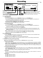
Connect -48VDC and Earth Ground to the terminal block as shown below. Nominal current draw is less than 100mA.
If a power supply protection fuse is used in series with the -48V supply, a 500mA slow blow fuse is recommended.
The initial start up current can surge as high as 600-700mA.
CHANNEL 1
BUSY
600 OHM
E&M
CO/PABX
LINE
PROGRAMMING
PORT
E&M
PROTOCOLS
48V
USE ONLY LISTED
CLASS 2 POWER
SOURCE 12VDC, 500mA
MAX
ON
GND
POWER
OFF
5 6 7 8
Channel 1 ring trip
interface
Connect to “Ringing”
C.O. or PABX line.
Dry contact closure for “E &
M” busy signal or “A” Lead
control
for “ring trip”.
Earth GND (+) 6
1 - 48V
M Lead (Start) 5
2 E Lead (Busy)
Tip (600 ohm) 4
3 Ring (600 ohm)
VIKING ELECTRONICS HUDSON WI. 54016
or
Connect to “ringing”
C.O. line or PABX
ext. for remote
recording
and
programming when
using “E & M”
interface. If “Ring
Trip” interface is
used, channel 1 or
the Programming
Port may be used.
- 48VDC
Earth GND
(+)
120V AC
Channel 1 four wire E & M interface
Programming
A. Standard Ring Trip Interface (Two Wire)
Any ringing C.O./PABX line will be answered, given an announcement and released. The DVA-3003 is then
immediately ready to answer the next incoming call. Set the front panel DIP switches to RING TRIP for each channel
using “Ring Trip” Interface, then momentarily disconnect power. *
B. Continuous Play 4 Wire E & M Interface
Set the front panel DIP switches to E & M for each channel using E & M Interface. Set “E & M protocols” DIP
switches to “A” (DIP switches 5 and 6 off). Invert the START signal (DIP switch 7 on). *Momentarily disconnect the
power. The announcement will be repeated continuously on pins 3 and 4 (600 ohm output).
C. 600 Ohm 4 Wire E & M Protocols
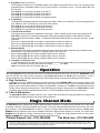
First set the front panel DIP switches to E & M for each channel using E & M Interface, then momentarily disconnect
power.* Four different protocols are now switch selectable for changing E & M timing, plus the ability to invert the
START and/or BUSY signals.
Front Panel DIP Switches
Channel
1 2 3
E&M
ON
Rear Panel E $ M Protocols DIP Switches
SW 5
PROTOCOL “A” OFF
PROTOCOL “B” OFF
PROTOCOL “C” ON
For future use
ON
SW 6
OFF
ON
OFF
ON
ON
OFF
5 6 7 8
Ring
Trip
SW 7 Inverted START signal when “ON”
Single
Channel
SW 8 Inverted BUSY signal when “ON”
* A momentary power down allows the DVA-3003 to read the new DIP switch settings.
2
E&M
Protocols