1
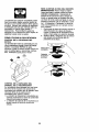
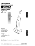
Owner's Manual
JCRIIFTSMAWJ
WHEELED
WEEDTRIMMER
6.0 Horsepower
22 Inch Cut
Model No.
917.773703
_IbCAUTION:
Read and follow all
Safety Rules and Instructions
before operating this equipment.
Sears, Roebuck and Co., Hoffman Estates, IL 60179 U.S.A.
Visit our Craftsman website: www.sears.com/craftsman
Warranty .................................................
2
Safety Rules ........................................
3-4
Assembly / Pre-Operation ......................
5
Operation .............................................
6-8
Maintenance
Schedule ..........................
9
Maintenance ......................................
9-12
LIMITED
TWO YEAR WARRANTY
Product Specifications ............................
9
Service and Adjustments ................. 13-14
Storage .................................................
15
Troubleshooting
...................................
16
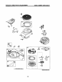
Repair Parts .....................................
34-42
Sears Service .........................
Back Cover
ON CRAFTSMAN
WEEDTRIMMER
For two years from date of purchase, when this Craftsman Weedtrimmer
is maintained,
lubricated, and tuned up according to the operating and maintenance
instructions in
the owner's manual, Sears will repair free of charge any defect in material or workmanship.
If this Craftsman Weedtrimmer
is used for commercial
applies for only 90 days from the date of purchase.
or rental purposes,
this warranty
This Warranty does not cover:
• Expendable
items which become worn during normal use, such as rotating lines,
belts, air cleaners and spark plug.
• Repairs necessary because of operator abuse or negligence,
including bent
crankshafts
and the failure to maintain the equipment according to the instructions
contained in the owner's manual.
Warranty service is available by returning the Craftsman
Sears Service Center in the United States. This warranty
is used in the United States.
This Warranty gives you specific
vary from state to state.
Sears, Roebuck
Weedtrimmer
to the nearest
applies only while this product
legal rights, and you may also have other rights which
and Co., Dept. 817 WA, Hoffman
Estates,
IL 60179
_, WARNING:
This trimmer is equipped with an internal combustion engine and
should not be used on or near any unimproved forest-covered,
brush-covered
or
grass-covered
land unless the engine's exhaust system is equipped with a spark
arrester meeting applicable local or state laws (if any). If a spark arrester is used, it
should be maintained
in effective working order by the operator.
In the state of California the above is required by law (Section 4442 of the California
Public Resources Code). Other states may have similar laws. Federal laws apply on
federal lands. A spark arrester for the muffler is available through your nearest Sears
service center (see the REPAIR PARTS section of this manual).
2
the eyes, which can result in severe eye damage.
Always wear safety
glasses or eye shields while operating your trimmer or performing any
adjustments
We recommend
standard
a
The
operationor ofrepairs.
any trimmer
can result in
foreign safety
objects glasses
thrown or
into
wide vision safety mask over spectacles.
can cause serious bums.
• Only allow responsible
individuals,
who are familiar with the instructions, to
operate the machine.
• Stay away from breakable objects,
such as house windows, auto glass,
greenhouses,
etc.
• Clear the area of objects such as rocks,
toys, wire, bones, sticks, etc., which
could be picked up and thrown by the
spinning lines.
• Be sure the area is clear of other
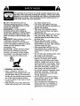
A, Look for this symbol to point out
important safety precautions.
It means
CAUTIONI![
BECOMEALERT!!!
YOUR
SAFETY IS INVOLVED.
WARNING:
In order to prevent
accidental starting when setting up,
transporting,
adjusting or making repairs,
always disconnect spark plug wire and
place wire where it cannot contact spark
plug.
AWARNING:
Engine exhaust, some of its
constituents,
and certain vehicle
components
contain or emit chemicals
known to the State of California to cause
cancer and birth defects or other
reproductive
people before trimming, particularly
small children and pets. Stop machine
if anyone enters the area.
• Wear appropriate clothing such as a
long-sleeved
shirt or jacket. Also wear
long trousers or slacks. Do not wear
shorts.
harm.
_1, CAUTION:
Muffler and other engine
parts become extremely hot during
operation and remain hot after engine
has stopped. To avoid severe burns on
contact, stay away from these areas.
I. GENERAL
• Do not wear loose clothing which could
get caught in this equipment.
• Do not operate the machine when
barefoot or wearing open sandals.
Always wear work gloves and sturdy
footwear. Leather work shoes or short
boots work well for most people. These
will protect the operator's ankles and
shins from small sticks, splinters, and
other debris, and improve traction.
• Do not pull machine backwards unless
absolutely necessary.
Always look
down and behind before and while
moving backwards.
• Do not operate the machine without
proper guards, plates or other safety
protective devices in place.
• See manufacturer's
instructions for
proper operation and installation of
accessories.
Only use accessories
approved by the manufacturer.
OPERATION
• Read, understand, and follow all
instructions on the machine and in the
manual before starting. Be thoroughly
familiar with the controls and the proper
use of the machine before starting.
• Do not put hands or feet near or under
rotating parts.
• Keep all parts of your body away from
muffler and spinning line. A hot muffler
3
IlL CHILDREN
• Never use blades, wire, or flailing
devices. This unit is designed for line
trimmer use only. Use of other accessories or attachments will increase the
risk of injury.
• Stop the rotating trimmer head when
crossing gravel drives, walks, or roads.
Wait for the cutting lines to stop
rotating.
• Stop the engine (motor) whenever you
leave the equipment and allow it to
cool, before cleaning, repairing or
inspecting the unit. Be sure the trimmer
head and all moving parts have
stopped.
• Operate only in daylight or good
artificial light.
• Do not operate the machine while
under the influence of alcohol or drugs.
• Never operate machine in wet grass.
Always be sure of your footing: keep a
firm hold on the handle and walk; never
run.
Tragic accidents can occur if the operator
is not alert to the presence of children.
Children are often attracted to the machine
and the trimming activity. Never assume
that children will remain where you last
saw them.
• Keep children out of the trimming area
and under the watchful care of another
responsible adult.
• Be alert and turn machine off if children
enter the area.
• Before and while moving backwards,
look behind & down for small children.
• Never allow children to operate the
machine.
• Use extra care when approaching blind
corners, shrubs, trees, or other objects
that may obscure vision.
IV. SERVICE
• Use extra care in handling gasoline
and other fuels. They are flammable
and vapors are explosive.
Use only an approved container.
- Never remove gas cap or add fuel
with the engine running. Allow
engine
to cool before refueling. Don't smoke.
Never refuel the machine indoors.
- Never store the machine or fuel
container inside where there is an
• If the equipment should start to vibrate
abnormally, stop the engine (motor)
and check immediately
for the cause.
Vibration is generally a warning of
trouble.
• Always wear safety goggles or safety
glasses with side shields when
operating
machine.
II. SLOPE
OPERATION
Slopes are a major factor related to slip
and fall accidents which can result in
open flame, such as a water heater.
Move away from fueling site before
starting engine.
Never run trimmer inside a closed area.
Never make adjustments or repairs
with the engine (motor) running.
Disconnect the spark plug wire, and
keep the wire away from the plug to
prevent accidental starting.
Keep nuts and bolts, especially trimmer
head and engine bolts, tight and keep
equipment
in good condition.
Never tamper with safety devices.
Check their proper operation regularly.
Keep machine free of grass, leaves, or
other debris buildup.
Clean oil or fuel
spillage.
Allow machine to cool before
cleaning or storing.
Stop and inspect the equipment if you
strike an object. Repair, if necessary,
before restarting.
Do not change the engine governor
-
severe injury. All slopes require extra
caution. If you feel uneasy on a slope, do
not trim it.
•
•
DO-
• Trim across the face of slopes: never
up and down. Exercise extreme
caution when changing direction on
slopes.
• Remove obstacles such as rocks, tree
limbs, etc.
• Watch for holes, ruts, or bumps. Tall
grass can hide obstacles.
•
•
•
DO NOT:
• Do not trim near drop-offs, ditches or
embankments.
The operator could
lose footing or balance.
• Do not trim excessively
steep slopes.
• Do not trim on wet grass. Reduced
footing could cause slipping.
•
•
4
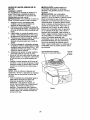
Read these instructions and this manual in its
TO REMOVE
entirety before you attempt to assemble or
operate your new trimmer.
IMPORTANT: This trimmer is shipped
WITHOUT OIL OR GASOLINE in the engine.
Your new trimmer has been assembled at the
TRIMMER
FROM CARTON
1, Remove loose parts included with
trimmer.
2. Cut down two end corners of carton
and lay end panel down flat.
3. Remove all packing materials.
4. Roll trimmer out of carton and check
carton thoroughly for additional loose
parts.
factory with the exception of those parts left
unassambled for shipping purposes. All parts
such as nuts, washers, bolts, etc., necessary
to complete the assembly have been placed
in the parts bag. To ensure safe and proper
operation of your trimmer, all parts and
hardware you assemble must be tightened
securely. Use the correct tools as necessary
to ensure proper tightness.
When right hand (RH) or left hand (LH) is
mentioned in this manual, it means when
you are in the operating position (standing behind the handle).
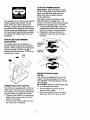
HOWTO
SET UPYOUR
TRIMMER
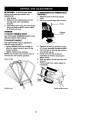
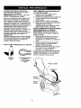
TO UNFOLD HANDLE
IMPORTANT: Unfold handle carefully so as
not to pinch or damage control cables.
1. Loosen handle knob enough to allow
upper handle to be unfolded from the
shipping position.
2. Raise upper handle section into place
on lower handle and tighten handle
knob.
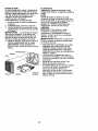
Loose Parts Packed Separately
3.
Remove handle padding holding
trimmer head control bar to upper
handle.
Your trimmer handle can be adjusted for
your trimming comfort. Refer to "ADJUST
HANDLE" in the Service and Adjustments
section of this manual.
Bottle of oil
Trimmer Lines
(2) sets
(0.155 diameter
x 18.75 inches long)
handle
LIFT UP
knob
handle
5
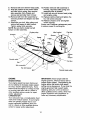
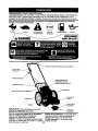
KNOW YOUR TRIMMER
READ THIS OWNER'S MANUALAND ALL SAFETY RULES BEFORE OPERATING YOUR
TRIMMER.
Compare the illustrations with your trimmer to familiarize yourself with the location
of various controls and adjustments. Save this manual for future reference.
_
symbolsmay appearon yourtrimrneror in literaturesuppliedwith the product.Learnand understand
their meaning.
FAST
SLOW
CAUTION
ENGINE OFF
FUEL
OIL
AVOIDSERIOUS
INJURYORDEATH
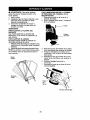
Trimmer head control bar
Throttle control
Starter handle
Engine oil cap
with dipstick
Handle
Muffler
Gasoline cal
cover
IMPORTANT: This trimmer is shipped
WITHOUT OIL OR GASOUNE in the engine.
Trimmer head control
bar. must
be held
down to the handle to engage trimmer head.
Release to stop the tnmmer head.
Primer - pumps additional fuel from the
carburetor to the cylinder for use when
starting a cold engine.
Throttle control - used for starting and
stopping the engine and allows you to select
either fast or slow engine speed.
Starter handle - used for starting the engine.
6
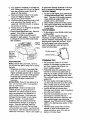
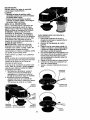
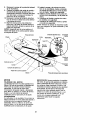
TO ADJUST TRIMMING HEIGHT
Aq_CAUTION: Stop the engine and wait
for all moving parts to stop. Disconnect
spark plug wire from spark plug and
place wire where it cannot come in
contact with plug.
The height of cut can be set to six (6)
different positions ranging from 1-1/2
inches to 3 inches. Recommended cutting
height for the average yard is 2 inches.
t. To adjust trimming height, push in the
locking plate tab and move trimmer
head up or down to desired position.
2. Release tab and be sure head is
The operationof any trimmer can result in
foreign objects being thrown into the
eyes, which can result in severe eye
damage. Always wear safety glasses or
eye shields while operating your trimmer
or performing any adjustments or repairs.
We recommend standard safety glasses
or a wide vision safety mask worn over
spectacles.
locked into one of the six (6) height
positions.
HOW TO USE YOUR TRIMMER
ENGINESPEED
Adjustable_
Trimmer
Head
The engine speed is controlled by a
throttle located on the side of the upper
handle. FAST position is for starting and
normal trimming. SLOW is for light
trimming and fuel economy. STOP is for
stopping the engine.
Lockin(
Plate Tab
@
BEFORE STARTING ENGINE
ADD OIL
Your trimmer is shipped without oil in the
engine. For type and grade of oil to use,
see "ENGINE" in the Maintenance section
of this manual.
TRIMMER
A CAUTION: DO NOT overfill engine with
oil, or it will smoke on startup.
1. Be sure trimmer is level and area
around oil fill is clean.
HEAD DRIVE CONTROL
Your trimmer is equipped with a trimmer
head drive control bar which will require
the operator to be positioned behind the
trimmer handle to operate the trimmer.
• Trimmer head rotation is controlled by
holding the trimmer head control bar
down to the handle.
• Trimmer head rotation will stop when
the control bar is released.
2.
7
Remove oil dipstick from oil fill spout.
Make sure that rim of spout is clean.
3. You receive a container of oil with the
unit. Slowly pour 3/4 (15 oz.) of the oil
from the container down the oil fill
or carburetor cleaner products in the fuel
tank or permanent damage may occur.
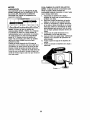
TO START ENGINE
spout into the engine.
4. Wait one minute to allow oil to settle.
Insert and tighten dipstick, then
remove it to check oil level.
1. To start a cold engine, push primer three
(3) times before trying to start. Use a firm
push. This step is not usually necessary
when starting an engine which has
already run for a few minutes.
2. Move throttle control lever to fast position.
3. Hold upper handle firmly and pull starter
handle quickly. Do not allow starter rope
to snap back.
TO STOP ENGINE
5.
Continue adding small amounts of oil
and rechecking the dipstick until it
reads full. DO NOT overfill, or engine
will smoke on startup.
6. Always be sure to retighten oil dipstick
before starting engine.
• Check oil level before each use. Add oil if
needed. Fill to full line on dipstick.
• Change the oil after every 25 hours of
operation or each season. You may need
to change the oil more often under dusty,
dirty conditions.
oil cap
Primer
Gasoline'
filler cap
(Discard
debris plug
inside)
ADD GASOLINE
NOTE: Before filling fuel tank, remove
and discard the debris plug that is inside
the tank.
• Fill fuel tank to bottom of gas tank filler
neck. Do not overfill. Use fresh, clean,
regular unleaded gasoline with a minimum
of 87 octane. Do not mix oil with gasoline.
Purchase fuel in quantities that can be
used within 30 days to assure fuel
freshness.
• i, CAUTION:
Wipe off any spilled oil or
fuel. Do not store, spill or use gasoline
near an open flame.
ACAUTION:
Alcohol blended fuels
• To stop engine, move throttle control lever
to stop position.
NOTE: In cooler weather it may be
necessary to repeat priming steps. In
warmer weather overpriming may cause
flooding and engine will not start. If you
do flood engine, wait a few minutes
before attempting to start and do not
repeat priming steps.
Throttle control
Starter handle--......_
TRIMMING TIPS
• Set the throttle control in the FAST
position. If the weeds or grass are tall
and thick, operate the trimmer at a
slower walking speed.
• Frequently clean the underside of the
trimmer to remove any grass build up.
Keep top of engine around starter clear
and clean of grass clippings and chaff.
This will help engine air flow and extend
engine life.
• For best results and longer lasting line,
use the ends of the line to do the cutting.
This is easily done by moving slowly
through very thick and heavy weeds.
• Use the left side of trimmer when
(called gasohol or using ethanol or
trimming along fences, walls, flowerbeds
methanol) can attract moisture which
and other such objects.
leads to separation
and formation of
• If trimmer lines become too short, it will
acids during storage. Acidic gas can
take longer to complete the job. If
damage the fuel system of an engine
trimmer lines are worn to less than half
while in storage.
To avoid engine
their original length, they should be
problems, the fuel system should be
replaced. See "TO REPLACE TRIMMER
emptied before storage of 30 days or
LINE" in the Maintenance section of this
longer. Drain the gas tank, start the
manual.
engine and let it run until the fuel lines
• Trimmer head contact with concrete,
and carburetor are empty. Use fresh fuel
asphalt or other hard surfaces may
next season. See Storage Instructions for
cause premature wear of the ball on
additional information.
Never use engine 8
bottom of trimmer head.
ASYOU
COMPLETE
0
RECUr,
SE.V,OE
Check for Loose Fasteners
If
T
Clean Tdmmer
al
Clean Under Engine Cover
M
Check ddve belt/pulleys
R
Check/Replace Trimmer Lines
I_
Check Engine Oil Level
If
I_
V'
V'
I/2
M#
I/
E Change
Engine
Oil
1_1,2
Clean Air Filter
_1 2
Inspect Muffler
i,/
I
r,
SE"VlOE
OATES
EN Clean or Replace Spark Plug
If
Replace Air Filter Paper Cartridge
if2
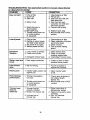
1 - Change more often when operating under a heavy load or in high ambient temperatures.
2 - Service more often when operating in dirty or dusty conditions.
3 - Replace trimmer lines when they have worn to haft their onginal length.
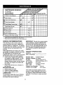
GENERAL
RECOMMENDATIONS
IMPORTANT:
Do not oil or grease plastic
wheel bearings. Viscous lubricants will
attract dust and dirt that will shorten the
The warranty on this trimmer does not
cover items that have been subjected to
operator abuse or negligence.
To receive
full value from the warranty, operator must
maintain trimmer as instructed in this
manual.
Some adjustments will need to be made
periodically to properly maintain your unit.
All adjustments in the Service and
Adjustments section of this manual should
be checked at least once each season.
life of the self- lubricating bearings. If you
feel they must be lubricated, use only a
dry, powdered graphite type lubricant
sparingly.
PRODUCT SPECIFICATIONS
Serial No.
Date of Purchase:
Gasoline Type:
Unleaded Regular
Gasoline Capacity: 1.6 Quarts
Oil Type:
SAE 30 (Above 32 g F)
(API-SF-SJ)
SAE 5W-30 (Below 32g F)
Oil Capacity:
20 ounces
Spark Plug :
Champion RJ19LM
(Gap: .030")
or J19LM
Trimmer Line Diameter:
.155 inch
Trimmer Line Length:
18.75 inches
•
Once a year, replace the spark plug
and replace air filter element.
A new
spark plug and clean/new air filter
element assure proper air-fuel mixture
and help your engine run better and
last longer.
•
Follow the maintenance
schedule in
this manual.
BEFORE EACH USE
1. Check engine oil level.
2. Check for loose fasteners.
The model and serial numbers will be
found on a decal attached to the rear of
the trimmer. Record both serial number
3. Clean under engine cover.
LUBRICATION
and date of purchase
above.
To prolong the useful life of your trimmer,
change engine oil as recommended
in
this section of Owner's Manual.
9
in space provided
TRIMMER
Always observe safety rules when performing any maintenance.
TIRES
• Keep tires free of gasoline, oil, or insect
control chemicals which can harm rubber.
• Avoid stumps, stones, deep ruts, sharp
objects and other hazards that may cause
tire damage.
TRIMMER LiNE
For best results, replace trimmer lines
when they have worn to half their original
length. Use .155 inch diameter trimmer
line. Cut new trimmer line length to 18-3/4
inches. After new line is installed on
TO REPLACE
trimmer head, check all lines so they do
not vary more then one (1) inch in length.
This is important to make sure the trimmer
head is balanced and will not vibrate
abnormally.
_WARNING:
Use only the specified
trimmer line. Do not use other materials
such as wire, string, rope, etc. Wire can
break off during trimming and become a
dangerous missile that can cause serious
injury.
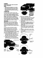
TO CUT LINE TO PROPER
TRIMMER
LINE
1. Disconnect spark plug wire from spark
plug and place wire where it cannot
come in contact with spark plug.
2. Remove worn trimmer line from line
carrier plate.
Fold new, cut to length, trimmer line in
half and insert folded end through
carrier plate opening to back side of
retainer clip.
4. With folded end of line at back side of
3.
LENGTH
NOTE: Trimmer line pre-cut to proper
length is available for this unit; see the
Repair Parts section of this manual.
If trimmer line is purchased in bulk, it must
be cut to 18-3/4 inches before using. Use
the built-in length guage as follows:
1. From front of trimmer, place the end of
spooled trimmer line at the mark on
the side of the debris shield as shown.
2. Wrap trimmer line around front of
chassis cover to other side and cut at
5.
6.
7.
retainer clip, pull line outward until
line is fully seated under the retainer
clip.
Repeat on other side of carrier plate.
Check all lines to be sure they are the
same length.
Reconnect spark plug wire to spark
plug.
Trimmer
line
the "22" mark (your unit's width of cut).
Carrier plate
opening
WRAP
LINE
Debris
shield
mark
End of
spooled line
New
trimmer
line
10
clip
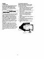
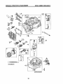
ENGINE
TO CHANGE
LUBRICATION
NOTE: Before tipping tdmmer to drain
oil, drain fuel tank by running engine
until fuel tank is empty.
Use only high quality detergent oil rated
with API service classification SF-SJ.
Select the oil's SAE viscosity grade
according to your expected operating
tem
-20
-30
0
-20
TEMPERATURE
30
-10
60
0
RANGE ANTICIPATED
10
BEFORE
80
20
OIL
1. Disconnect spark plug wire from spark
plug and place wire where it cannot
come in contact with spark plug.
2. Remove engine oil cap; lay aside on a
clean surface.
3. Tip trimmer on its side as shown and
drain oil into a suitable container.
Rock trimmer back and forth to
100
30
ENGINE
40
NEXT OIL CHANGE
NOTE: Although multi-viscosity
oils
(5W30, 10W30 etc.) improve starting in
cold weather, these multi-viscosity oils
will result in increased oil consumption
when used above 32°F. Check your
engine oil level more frequently to avoid
possible engine damage from running
low on oil.
4.
5.
6.
7.
remove any oil trapped inside of
engine.
Wipe off any spilled oil from trimmer or
side of engine.
Fill engine with oil (See "ADD OIL" in
the Operation section of this manual).
Replace engine oil cap.
Reconnect spark plug wire to spark
plug.
Change the oil after every 25 hours of
operation or at least once a year if the
unit is not used for 25 hours in one year.
Check the crankcase oil level before
starting the engine and after each five (5)
hours of continuous use. Tighten oil plug
securely each time you check the oil
level.
Container
11
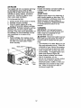
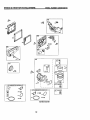
MUFFLER
AIR FILTER
Your engine
be damaged
Replace the
operation or
occurs first.
will not run properly and may
by using a dirty air filter.
air filter every 100 hours of
every season, whichever
Service air cleaner more
often under dusty conditions.
TO CLEAN AIR FILTER
1. Loosen screw and tilt cover to remove.
2.
3.
Carefully remove cartridge.
Clean by gently tapping on a flat
surface. If very dirty, replace cartridge.
ACAUTION:
Petroleum solvents, such as
kerosene, are not to be used to clean
cartridge. They may cause deterioration
of
the cartridge. Do not oil cartridge. Do not
use pressurized
air to clean or dry
cartridge.
4. Install cartridge, then replace cover
making sure the tabs are aligned with
the slots in the back plate. Fasten
screw securely.
Inspect and replace corroded muffler as
it could create a fire hazard end/or
damage.
SPARK PLUG
Replace spark plugs at the beginning of
each mowing season or after every 100
hours of operation, whichever occurs first.
Spark plug type and gap setting are
shown in "PRODUCT SPECIFICATIONS"
in the Maintenance
section of this
manual.
CLEANING
IMPORTANT:
For best performance,
keep trimmer free of built-up grass and
trash. Clean the underside of your
trimmer after each use.
ACAUTION:
Disconnect spark plug wire
from spark plug and place wire where it
cannot come in contact with the spark
plug.
• Turn trimmer on its side. Make sure air
filter and carburetor are up. Clean the
underside of your trimmer by scraping
to remove build-up of grass and trash.
• Clean engine often to keep trash from
accumulating.
A clogged engine runs
hotter and shortens engine life.
• Keep finished surfaces and wheels
free of all gasoline, oil, etc.
• We do not recommend
using a garden
hose to clean trimmer unless the
Back
Slots
Cover
electrical system, muffler, air filter and
carburetor
are covered to keep water
out. Water in engine can result in
shortened
engine life.
Cover
tabs
12
A
WARNING:
To avoid serious injury,
before performing any service and
adjustments:
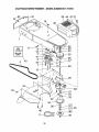
TO REMOVE/REPLACE TRIMMER HEAD
DRIVE BELT
1. Remove screw at front of chassis
cover.
2. Lift cover up and away from trimmer.
1. Stop engine.
2. Make sure the rotating lines and all
moving parts have completely
stopped.
3. Disconnect spark plug wire from spark
plug and place where it cannot come
in contact with plug.
TRIMMER
TO ADJUST TRIMMING
Chassis
cover
HEIGHT
See 'qO ADJUSTTRIMMING
HEIGHT" in the
Operation section of this manual.
TO ADJUST
HANDLE
The upper handle may be adjusted to
different height positions.
• Loosen handle knob only enough to
allow the upper handle to pivot to the
desired position.
• Tighten handle knob securely.
NOTE: The handle knob and bolt may be
reversed for left handed operation.
3.
Remove the two (2) screws on sides
of trimmer securing the debris shield.
4. Turn trimmer on its side with carburetor and fuel cap up.
Remove the two (2) screws on
underside of trimmer securing the
debris shield.
6. Slide the debris shield rearward and
remove.
5.
Upper handle
7.
Remove belt from engine pulley on
crankshaft.
pulley
Handle knob J
Debris shietd screws
13
8.
9.
Remove belt from trimmer head pulley.
Note the position of the control cable
and idler return spring, then remove
idler assembly from chassis and
remove belt and idler from trimmer.
10. Remove belt from idler assembly by
removing bottom belt keeper and idler
pulleys.
11.Assemble new belt, idler pulleys and
bottom belt keeper to idler bracket.
Tighten pulley bolts securely.
NOTE: Be sure belt is inside top belt
keeper on idler assembly.
12. Position belt and idler assembly in
trimmer, reconnect idler spring and
assemble idler to chassis.
13.Install belt around trimmer head pulley
and engine pulley.
14. Replace debris shield and tighten the
four (4) screws securely.
15. Replace chassis cover and tighten
screw securely.
Always use Craftsman replacement parts
to assure proper fit and long life.
Idler bracket
Flatidler
Spacer,
BoSom
belt
keeper
Flat idler
2
Trimmer head pulley
ENGINE
ENGINE
IMPORTANT:
Never tamper with the
engine governor, which is factory set for
proper engine speed. Overspeeding the
engine above the factory high speed
setting can be dangerous. If you think the
engine-governed
high speed needs
adjusting, take your unit to a Sears or
other qualified service center, which has
proper equipment and experience to
make any necessary adjustments.
SPEED
Your engine speed has been factory set.
Do not attempt to increase engine speed
or it may result in personal injury. If you
believe that the engine is running too fast
or too slow, take your unit to a Sears or
other qualified service center for repair
and/or adjustment.
CARBURETOR
Your carburetor has a nonadjustable
fixed
main jet for mixture control. If your engine
does not operate properly due to suspected carburetor problems, take your
unit to a Sears or other qualified service
center for repair and/or adjustment.
14
Immediately prepare your trimmer for storage
at the end of the season or if the unit will not
be used for 30 days or more.
TRIMMER
When trimmer is to be stored for a period of
time, clean it thoroughly, remove all dirt,
grease, leaves, etc. Store in a clean, dry area.
1. Clean entire trimmer (See "CLEANING" in
the Maintenance section of this manual).
2. Lubricate as shown in the Maintenance
section of this manual.
3. Be sure that all nuts, bolts, screws, and
[:)ins are securely fastened. Inspect
moving parts for damage, breakage and
wear. Replace if necessary.
4. Touch up all rusted or chipped paint
surfaces; sand lightJy before painting.
HANDLE
You can fold your trimmer handle for storage.
• Loosen handle knob enough to allow
upper handle to be folded forward.
IMPORTANT: When folding the handle for
storage or transportation, be sure to fold the
handle as shown or you may damage the
control cables.
.... ";........
;,'
tank during storage. Also, alcohol blended
fuels (called gasohol or using ethanol or
methanol) can attract moisture which leads to
separation and formation of acids during
storage. Acidic gas can damage the fuel
system of an engine while in storage.
1. Drain the fuel tank.
2. Start the engine and let it run until the
fuel lines and carburetor are empty.
• Never use engine or carburetor cleaner
products in the fuel tank or permanent
damage may occur.
• Use fresh fuel next season.
NOTE: Fuel stabilizer is an acceptable
altemative in minimizing the formation of fuel
gum deposits during storage. Add stabilizer
to gasoline in fuel tank or storage container.
Always follow the mix ratio found on stabilizer
container. Run engine at least 10 minutes
after adding stabilizer to allow the stabilizer to
reach the carburetor. Do not drain the gas
tank and carburetor if using fuel stabilizer.
ENGINEOIL
Drain oil (with engine warm) and replace with
clean engine oil. (See "ENGINE' in the
Maintenance section of this manual).
CYLINDER
1. Remove spark plug.
2. Pour one ounce (29 ml) of oil through
spark plug hole into cylinder.
3. Pull starter handle slowly a few times
to distribute oil.
4.
Replace
with new spark plug.
OTHER
Upper
handle
,,;
Handle knob
ENGINE
FUEL SYSTEM
IMPORTANT: It is important to prevent gum
deposits from forming in essential fuel system
parts such as carburetor, fuel filter, fuel hose or 15
• Do not store gasoline from one season to
another.
• Replace your gasoline can it your can
starts to rust. Rust and/or dirt in your
gasoline will cause problems.
• If possible, store your unit indoors and
cover it to give protection from dust and dirt.
• Cover your unit with a suitable protective
cover that does not retain moisture. Do
not use plastic. Plastic cannot breathe
which allows condensation to form and will
cause your unit to rust.
IMPORTANT: Never cover trimmer while
engine and exhaust areas are still warm.
_I, CAUTION:
Never store the trimmer
with gasoline in the tank inside a building
where fumes may reach an open flame or
spark. Allow the engine to cool before
storing in any enclosure.
TROUBLESHOOTING
to a Sears Service
PROBLEM
Does not start
- See appropriate section in manual unless directed
Center.
CAUSE
CORRECTION
1. Dirty air filter.
2. Out of fuel.
3. Stale fuel.
4. Water
1. Clean/replace
air filter.
2. Fill fuel tank.
3. Drain tank and refill with
fresh clean fuel.
4. Drain fuel tank and
carburetor and refill tank
with fresh gasoline.
5. Connect wire to plug.
in fuel.
5, Spark plug wire is
disconnected.
Loss of power
Excessive
Vibration
6. Bad spark plug.
7. Throttle control lever not
in correct position
(if equipped).
6. Replace spark plug.
7. Move throttle lever to FAST
position.
1. Dirty air filter.
2. Buildup of grass, leaves,
and trash under trimmer.
3. Too much oil in engine.
4. Walking speed too fast.
1. Clean/replace
air filter.
2. Clean underside of trimmer
and trimmer head.
3. Check oil level.
1. Lines uneven or broken.
2. Loose nuts or bolts.
1. Check trimmer lines.
2. Check all hardware,
including engine bolts.
3. Check/repair
trimmer head.
3. Damaged
trimmer
head.
Starter rope hard
to pull
1. Bent engine
Loss of head
drive
t. Belt not driving.
Hard to push
1. Handle height
right for you.
Poor trimming
performance
1. Trimmer line length is
too shod.
crankshaft.
1. Contact a Sears or other
qualified service center.
1. Put belt on pulleys or
replace belt if broken.
position
no1
2. Throttle control lever not
in correct position
(if equipped).
Trimmer head
does not
retain line
4. Trim at slower walking
speed.
1. Trimmer line not
properly installed.
2. Broken line retainer
3. Incorrect size of
trimmer line.
16
clip.
1. Adjust handle
to suit.
height
1. If line is worn or broken to
half original length,
replace line.
2. Move throttle lever to FAST
position.
1. Follow instructions in
Maintenance
section.
2. Replace string carrier plate
assembly.
3. Use .155 diameter
trimmer line.
I
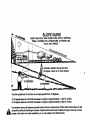
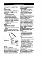
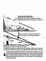
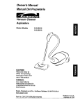
Operate
a trimmer aQross the face
of slopes,
never up or down slopes.
I
I
,r..
I
10
EES
15 DEGREES
l+
Use this guide
A 10 degree
A 15 degree
r_
and
slope
slope
do not trim on s elope
Is a hill that Increassm
Is • hill that Increases
greater
in height
In height
than
15 degrees.
at approximately
at approximately
1.7 feet In 10 feet.
2.5 feet in 10 feet.
Use extreme care at all times and avoid sudden turns or maneuvers.
Follow other Instructions in this
manual for safety in trimming on slopes. Operate a trimmer aerobe the face of slopes, never up or down
slopes. Use extra care when operating on or near elopes and obstructions.
Garantfa ......................................................... 18
Reglas de Seguridad ................................ 19-20
Montaje / Pre-Operaci6n ............................... 21
Operaci6n ................................................. 22-25
Mantenimiento .......................................... 26-29
Programa de Mantenimiento .......................... 26
Especificaciones del Producto ...................... 26
Servicio y Adjustes .................................. 30-31
Almacenamiento ............................................. 32
Identificaci6n de problemas ........................... 33
Partes de repuesto .................................. 34-42
Servicio Sears ................................. Contratapa
GARANTfA LIMITADA DE DOS AltOS PARA LA RECORTADORA PAPA MALA HIERBA PARA
MALA HIERBA CRAFTSMAN
Por dos (2) aSos, a partir de la fecha de compra, cuando esta recortadora para mala hierba
Craftsman se mantenga, lubdque y afine seg_n las instrucciones para la operaci6n y el
mantenimiento en el manual del dueSo, Sears reparard gratis todo defeeto en el material y la
mano de obra.
Si la recortadora para mala hierba Craftsman se usa para fines comerciales o de arriendo, esta
garanfia s61ose aplica pot noventa (90) dfas a partir de la fecha de compra.
Esta Garantfa no cubre:
• Art{culos que se desgastan durante el uso normal tales come las lineas rotatorias, las
correas, los filtros de aire y las bujfas.
• Reparaciones necesadas debido al abuso o a la negligencia del operador, incluydndose a los
cig0eSales doblados y a la falta de mantenimiento del equipo seg=Jnlas instrucciones que se
incluyen en el manual del due£=o.
El servicio de garantia esta disponible al devolver la recortadora para mala hierba Craftsman al
Centro de Servicio Sears mas cercano en los Estados Unidos. Esta garantfa se aplica
solamente mientras el producto este en uso en los Estados gnidos.
Esta Garant_a le otorga derechos legales especfficos, y puede que tambidn tenga otros derechos
que varfan de estado a estado.
Sears, Roebuck
and Co., Dept. 817 WA, Hoffman
Estates,
Illinois 60179
U.S.A.
• 1_ADVERTENClA: Este recortadora viene equipado con un motor de combusti6n interna y no
se debe usar sobra, o cerca, de un terreno no desarrollado cubierto de bosques, de arbustos o
de c_sped, o menos que el sistema de escape del motor venga equipado con un amortiguador
de chispas que cumpla con las leyes locales o estatales (si existen). Si se usa un amortiguador
de chispas, el operador debe mantenerlo en condiciones de trabajo eficientes.
En el estado de California, la ley exige Io anterior (Secci6n 4442 del =California Public Resources
Code"). Otros estados pueden contar con otras leyes paracidas. Las leyes federales se aplican
en fa tierras federales. Su Centro/Departamento de Servicio Sears m_.scercano tiene disponible
amortiguadores de chispas para el silenciador. (Vea la secci6n de Partes de Repuesto en el
manual Ingles del dueSo.)
18
&
&
La operaci6n de cualquier recortadora puede hacer que salten objetos
extrafios dentre de sus ojos, Io que puede producir dai_os graves en _stos.
Siempre use anteojos de seguridad o protecci6n para los ojos mientras opere
su recortadora o cuando haga ajustes o reparaciones. Recomendamos
gafas de seguridad o una mdscara de visi6n amplia, de seguridad usada
sobre las galas.
_l, Busque este sfmbolo que sefiala las
precauciones de seguddad de importancia.
Quiere decir - iiiATENCI6Nfl!iilESTE
ALERTO!(( SU SEGURIOAD ESTA
COMPROMETIDA.
_.DVERTENClA:
Siempre desconecte el
alambre de la bujfa y p6ngalo donde no pueda
entrar en contacto con la bujfa, para evitar el
arranque por accidente, durante la
preparaci6n, el transporte, el ajuste o cuando
se hacen reparaciones.
_LPRECAUCl6N: El tubo de escape del motor,
algunos de sus constituyentes y algunos
componentes del vehfculo contienen o
desprenden productos qufmicos conocidos en
el Estado de California como causa de c_.ncer
y defectos al nacimiento u otros dafios
reproductivos.
_PRECAUCI6N:
El silenciador y otras piezas
del motor Ilegan a sre extremadamente
calientes durante ]a operaci6n y siguen siendo
calientes despu_s de que el motor haya
parado. Para evitar quemaduras severas,
permanezca le[os de estas areas.
• Permita que solamente las personas
responsables que estOn familiarizadas con
las instrucciones operen la m_.quina.
• Mantenerse lejos de objetos que pueden
romperse, como cristales de casa, cristales
del choche, invernaderos, etc.
• Despeje el _rea de objetos tales como
piedras, juguetes, alambres, huesos, palos,
etc. que pueden ser recogidos y lanzados
por las I(neas giradoras.
• AsegSrese que el _rea no se hallen
personas, y particularmente nifios pequefios
y caohorres antes de recortar. Pare la
m&quina si alguien entra en el _rea.
• Use ropa apropaida, tal como camisa de
manga larga o chaqueta y pantalones
largos. No use pantalones cortos shorts.
• No use ropa suelta, ya que Osta podfia
atorerse en el equipo.
• No opere la maquina sin zapatos o con
sandalias abiertas. Use siempre guantes de
trabajo y calzado fuerte. Los zapatos de
trabajo de piel o botas cortas son
apropiados para la mayorfa de las personas.
Estos no s61o protegeri._nlos tobillos y
espinellas del operador de pequefias ramas,
astillas y otros desperdicios, sino que
ademas mejorar&n la tracci6n.
• No tire de la m&quina hacia atr._s a menos
que sea absolutamente necesario. Mire
siempre hacia abajo y hacia detr&s antes y
mientras que se mueve hacia atr_.s.
• No opere la maquina sin los respectivos
resguardos, placas u otros aditamentos
disefiados para su protecci6n y seguridad.
• Refi_rase alas instrucciones del fabricante
para el funcionamiento e instalaci6n de
accesorios. Use enicamente accesorios
aprobados por el fabricante.
• Nuca utilice cuchillas, cables o dispositivos
tipo mayal. Esta unidad est,. proyectada
para fucionar solamente con una Ifnea de
recortadora. La utilizaci6n de cualquier otro
material, acessorio o dispositivo secundario
aumenta el nesgo de lesi6nes y dafios a la
propiedad.
I. OPERACI(_N GENERAL
• Antes de empezar, debe familiarizarse
completamente con los controles y el uso
correcto de la maquina. Para esto, debe leer
y comprender todas las instrucciones que
aparecen en la maquina yen los manuales
de operaci6n.
• No ponga las manos o los pies cerca o
debajo de las partes rotatorias.
• Mantener todas las partes del cuerpo lejos
del silenciador del escape y la Ifnea de
rotaci6n. El silenciador caliente puede
causar serias quemaduras.
19
• Detenga la cabeza giratoria de la
recortadora cuando cruce por calzadas,
calles o caminos de grava. Espere que las
cuerdas de corte paren de girar.
• Pare el motor siempre que tenga que dejar
el equipo, antes de limpiar, reparar o
inspeccionar la unidad. Aseg_rese de que la
cabeza de la recortadora y todas las partes
en movimiento se hayan detenido.
• Opere solamente con luz del dla o con una
buena luz artificial.
• No opera la m_quina bajo la influencia del
alcohol o de las drogas.
• Nunca opera la maquina cuando la hierba
est_ mojada, AsegOrase siempre de tener
buena tracci6n en sus pies; mantenga el
mango firmemente y camine; nunca corra.
• Si el equipo empezara a vibrar de una
manera anormal, pare el motor y revise de
inmediato para averiguar la causa.
Generalmente la vibraci6n suele indicar que
existe alguna averfa.
• Siempra use gafas de seguridad o anteojos
con protecci6n lateral cuando opera la
maquina.
II. OPERACI(_N EN PENDIENTE
Los accidentes ocurren con m_s frecuencia
en las cuestas. Estos accidentes ocurren
debido a resbaladas o cafdas, las cuales
pueden resultar en graves lesiones. Operar la
recortadora en cuestas requiere mayor
concentraci6n. Si se siente inseguro en una
cuesta, no la recorte.
SI:
• Puede recortar a tray,s de la superficie de
la cuesta, nunca hacia arriba y hacia abajo.
Proceda con extrema precauci6n cuando
cambie de direcci6n en las cuestas.
• Renueva todos los objetos extrafios, tales
como guijarros, ramas, etc.
• Debe prestar atenci6n a hoyos, baches o
protuberancias. Recuerde que la hierba alta
puede esconder obst&culos.
NO:
• No recorte cerca de pendientes, zanjas o
terraplenes. El operador puede perder la
tracci6n en los pies o el equilibrio.
• No recorte cuestas demasiado inclinadas.
• No recorte en hierba mojada. La reducci6n
en la tracci6n de la pisada puede causar
resbalones.
lit. NII_IOS
Se pueden producir accidentes tr_gicos si el
operador no presta atenci6n a la presencia de
los nihos. A menudo, los niflos se sienten
atrafdos pot la m_.quina y por la actividad de la
siega. Nunca suponga que los nifios van a
permanecer en el mismo lugar donde los vio
por eltima vez.
• Mantenga a los nifios alejados del drea de la
siega y bajo el cuidado estdcto de otra
persona adulta rasponsable.
• Estd alerta y apague la mdquina si hay
nifios que entran al drea.
• Antes y durante el retroceso, mire hacia
atrds y hacia abajo para verificar si hay
nihos pequehos.
• Nunca permita que los nifios operan la
m_quina.
• Tenga un cuidado extra cuando se acerque
a esquinas donde no hay visibilidad, a los
arbustos, drboles u otros objetos que
pueden interterir con su linea de visi6n.
IV. SERVICIO
• Tenga cuidado extra al manejar la gasolina
y los dem&s combustibles. Son inflamables
y los gases son explosivos.
- Use solamente un envase aprobado.
- Nunca ramueva la tapa del dep6sito de
gasolina o agregue combustible con el
motor funcionando. Permita que el motor
se enfrfe antes de volver a poner
combustible. No fume.
- Nunca vuelva a porter combustible en la
mdquina en recintos cerrados,
- Nunca almacene la m&quina o el envase
del combustible dentro de algOn lugar en
donde haya una llama expuesta, tal como
la del calentador de agua.
• Alejarse de la zona de abastecimiento del
carburante antes de poner en marcha.
• Nunca haga funcionar una mdquina dentro
de un &rea cerrada.
• Nunca haga ajustes o reparaciones
mientras el motor est_ en marcha.
Desconecte el cable de la bujia, y
mantdngalo a cierta distancia de dsta para
prevenir un arranque accidental.
• Mantenga las tuercas y los pemos,
especialmente los pemos del motor y de la
cabeza de recortes, apretados y mantenga
el equipo en buenas condiciones,
• Nunca manipule de forma indebida los
dispositivos de seguridad. Controle
regularmente su funcionamiento correcto.
• Mantenga la mdquina libre de hierba, hojas
u otras acumulaciones de desperdicio.
Limpie los derrames de aceite o combustible. Permita que la m&quina se refresque
antes de limpiarla o almacenarla.
• Pare e inspeccione el equipo si le pega a un
objeto. Rep&relo, si es necesario, antes de
hacerlo arrancar.
• No cambie el ajuste del regulador del motor
ni exceda su velocidad.
• Limpiar y sustituir las calcomanias relativas
a instrueeiones y seguridad cuando
necesario.
20
Lea estas instrucciones y este manual
completamente antes de tratar de montar u
operar su nueva recortadora.
IMPORTANTE: Esta recortadora viene SIN
ACEITE O GASOLINA en el motor.
Su nueva recortadora ha side montada en la
fdbrica con la excepci6n de aquellas partes
qua se dejaron sin montar por razones de
envio. Todas las partes como las tuercas, las
arandelas, los pernos, etc., necesarias para
completar el montaje han side colocadas en la
bolsa de partes. Para asegurarse que su
recortadora funcione de forma segura y
adecuada, todas las partes y los articulos de
ferretefia que se monten tienen que set
apretados firmemente. Use las herramientas
correctas adecuadas para asegurar un
apretado firme.
Cuando la mano derecha o la mano izquierda
estdn mencionadas en este manual, significa
que usted esta situado en la posici6n de
operador, detrds del mango.
PARA REMOVER LA RECORTADORA DE
LA CAJA DE CARTON
1. Remueva las partes sueltas que se
incluyen con la recortadora.
2. Corte las dos esquinas de los extremos de
la caja de cart6n y tienda el panel del
extremo piano.
3. Remueva todo el material de embalaje.
4. Haga rodar la recortadora hacia afuera de
la caja de cart6n y revisela
cuidadosamente para verificar si todavfa
quedan partes sueltas adicionales.
COMO PREPARAR
SU RECORTADORA
PARA DESDOBLAR
EL MANGO
IMPORTANTE: Despliegue el mango con
mucho cuidado para no apretar o daSar los
cables de control.
1. Aflojar la perilla del mango Io suficiente
para permitir el mango superior ser
desdoblado con respecto a la posici6n de
envio.
2. Levante la secci6n del mango superior
hasta su lugar en el mango inferior, y
apdete la manilla del mango.
3. Remueva ta cuSa del mango que sujeta la
barra del control del cabezal de la
recortadora al mango superior.
El mango de su recortadora puede ajustarse
segSn le acomode para recortar. RefiSrase a
"AJUSTE DEL MANGO" en la Secci6n de
Servicio y Ajustes de este manual.
Piezas sueltas empaquetadas por separado
Botella de
acelte
2 Juegos de cuerda de
recortadora
(0.155 de dldmetro
x 18.75)
Mango supedor
LEVANTAR
de mango
Mango
inferior
21
FAMILIAR|CESE CON SU RECORTADORA
LEA ESTE MANUAL DE USUARIO Y LAS REGLAS DE SEGURIDAD ANTES DE OPERAR SU
RECORTADORA. Compare las ilustraciones con su recortadora para familiarizarse con la
ubicaci6n de los diversos controles y ajustes. Guarde este manual para referencia en el futuro.
Estossimbolospuedenaparecersobresu recortadorao on laspdginasproporcionadasconel producto.
Aprenday comprendasussignificados.
R,i_PIDO
LENTO
ATTENCI(_N
O
ADVERTENCIA
MOTOR
COMBUSTIBLE
ACEITE
APAGADO
AVOIDSERIOUS
,WARNING
INJURY
ORDEATH
Barra de mando del cabezal de la recortadora
Control de la
acoleracibn
Cord6n arrancador
Tapa del depositode
aceite del motor con
Tapa del deposito de la gasolina
Filtn
Cubierta del
s
Cabeza de la
IMPORTANTE: Esta recortadora viene SIN
ACEITE O GASOLINA en el motor.
Barra de mando del cabizal de la recortadom debe ser presionada hacia el mango para
engancharel cabezal de la recortadom,
Cebador - bombea combustibleadicionaldesde el
carburadoral cilindropara use cuando sa necesita
hacer arrancar un motor fifo.
22
Linea de la
recortadora
Control de la aceleraci6n - se usa para hacer
arrancarel motory le permitoseleccionarla
velecidaddel motorya sea _pida o lenta.
Cord6n arrancador - se usa para hacer
arrancar el motor.
PARA AJUSTAR ALTURA DEL RECORTE
_PRECAUCI6N:
Pare el motor y espere
hasta que todas la piezas m6viles se hayan
detenido completamente. Desconecte el
alambre de la bujfa de la bujia y p6ngalo en
donde no pueda entrar en contacto con 6sta.
La altura del corte puede ser fijada en seis (6)
diversas posiciones que se extienden a partir
de 1-1/2 pulgadas a 3 pulgadas. La altura de
corte recomendada para un cercado normal
es 2 pulgadas.
1. Para ajustar la altura del recorte, empuje la
aleta tabulaci6n de la placa de bloque y
mueva el cabezal de la recortadora hacia
arriba o hacia abajo a la posici6n deseada.
2. Suelte la aleta y aseg5rese que el cabezal
este situado en una de las seis (6)
posiciones de la altura.
La operaci6n de cualquier recortadora puede
hacer que salten objetos extraSos dentro de
sus ojos, Io que puede producir daSos graves
en estos. Siempre use anteojos de seguridad
o protecci6n para los ojos mientras opere su
recortadora o cuando haga ajustes o
reparaciones. Recomendamos gafas de
seguridad o una m;_scarade visi6n amplia, de
seguddad usada sobre las gafas.
COMO UTILIZAR
SU RECORTADORA
CONTROL DE LA VELOCIDAD DEL
MOTOR
La velocidad del motor es controlada por una
vdIvula reguladora situada al lado del mango
superior. La posicibn R_,PIDA es para
comenzar y para el recorte normal. LENTO es
para el recorte ligero y economizar combustible. PARADA es para parar el motor.
..
Cabeza de la_
recortadora
Tabulaci6n
@
de bloque
CONTROL DE LA IMPULSI6N DEL
CABEZAL DE LA RECORTADORA
Su recortadora viene equipada con una barra
de control de la impulsi6n del cabezal de la
recortadora que requiera que e; operador este
colocado detr_.sde la palanca de la
recortadora para operar la misma.
• La rotaci6n del cabezal de la recortadora se
controla manteniendo la barra de control del
cabezal hacia abajo al mango,
• La rotaci6n del cabezal de la recortadora se
parard cuando la barra de control sea
soltada.
23
ANTES DE HACER ARRANCAR
EL
MOTOR
AGREGUE ACEITE
Su recortadora fue enviada sin aceite en el
motor. Para el tipo y el grado del aceite a
utilizar, vea el "MOTOR" en la seccibn del
Mantenimiento de este manual.
_PRECAUCl6N:
NO sobrellene el motor con
aceite, o fumard cuando Io valla a arrancar.
1. Aseg_rese que la recortadora est_
nivelada y que el &rea alrededor del
depSsito de aceite est_ limpia.
2. Remueva la varila medidora de aceite del
tubo de desarga de aceite. AsegOrese que
el borde del tubo de relleno de aceite este
limpio.
3. Usted recibe un envase de aceite con la
unidad. Vierta lentamente 3/4 (15 onzas)
de aceite en el tubo de relleno del motor.
4. Permita que el aceite se asiente. Inserte y
apdete la varilla medidora de aceite,
despu6s remuevala para leer el nivel de
aceite.
5. ContinUe agregando cantidades pequeas
de aceite y vuelva a inspeccionar la varilla
medidora hasta que lea Ileno (FULL). NO
sobrellene el motor con aceite, o fumar&
cuando Io valla a arrancar.
6. Aseg_rese de apretar la vadlla medidora
del aceite antes de arrancar el motor.
• Revise el nivel del aceite antes de cada uso.
Agregue aceite si es necesario. Llene hasta
la Ifnea de lleno en la varilla medidora de
nivel.
• Cambie el aceite despu_s de 25 horas de
operaci6n o una vez por temporada. Puede
necesitar cambiar el aceite m&s a menudo
cuando las condiciones son polvorosas o
sucias.
GASOLINA
AVISO: Antes de rellenar el deposito de
carburante, remover y descartar los residuos
del tapon que se encuentran al interior del
deposito.
• Liens el estanque de combustible hasta la
parte inferior del cuello de relleno del
estanque de gasolina. No Io Ilene
demasiado. Use gasolina regular, sin
plomo, nueva y limpia con el minimo de 87
octanos. No mezcle el aceite con la
gasolina. Para asegurar que la gasolina
utilizada sea fresca compre estanques los
cuales puedan set utilizados durante los
primeros 30 dias.
_I_PRECAUCI6N: Limpie el aceite o el
combustible derramado. No almacene,
derrame o use gasolina cerca de una llama
expuesta.
_kPRECAUCI(_N: Los combustibles
mezclados con alcohol (conocidos como
gasohol, o el uso de etanol o metanol) pueden
atraer la humedad, la que conduce a la
separacibn y formacibn de _cidos durante el
almacenamiento. La gasolina acidica puede
dahar el sistema del combustible de un motor
durante el almacenamiento. Para evitar los
problemas con el motor, se debe vaciar el
sistema de! combustible antes de guardarlo
por un periodo de 30 dfas o m_s. Vacfe el
estanque del combustible, haga arrancar el
motor y h&galo funcionar hasta que las lineas
del combustible y el carburador queden
vacfos. La pr6xima temporada use
combustible nuevo. Vea las Instrucciones Para
El Almacenamiento para m_.sinformaci6n.
Nunca use productos de limpieza para el
motor o para el carburador en el estanque del
combustible puss se pueden producir daSos
permanentes.
Tapa del rellenadorde gasolina
(Descartar los reslduosdel Tapon)
/
Cebador
24
Tapa del
deposito
de aceite
PAPA HACER ARRANCAR EL MOTOR
1. Para hacer arranoar un motor fr[o, empuje
et osbador tros (3) veces antes de iniciar.
Empuje firmemente. Este paso
normalmente no es necssario cuando se
hace arrancar un motor que ya ha estado
funcionando por unos cuantos minutos.
2. Mueva la palanca de control de la
aceleraci6n a la posici6n mas r_.pida.
3. Sujete la barra de control superior y tire del
mango del arranoador r_ipidamente. No
permita que el cord6n arrancador se
devuelva abruptamente.
PAPA PARAR EL MOTO
• Para parar el motor,mueva la palancade
controlde la aceleracibna la posici6nde
parada.
AVISO: En climas m_s frios puede que sea
necesafiorepeSrlos paros del osbade. En dimas
rnds calurososel cebar demasiado puede
producir el ahogo y el motor no va a a_.
Si
se ahoga el motor espere unos cuantosminutos
antes de tratar de hacerlo arrancar y no rep'_alos
pasos del cebado.
AVISO PAPA RECORTAR
• _e el controlde la aceleradOn a la posid6n
RAPID/_ Si las malos hierbaso el c_sped est_
altos y gruesos,opere la recortaderaa una
velocidadde paso rn&slento.
• Umpie con frecuencia la superficieinferiorde la
recortadorapara remueva cuaJquier
acumulaci6nde hierba. Mantengala superrmie
del motora]rededordel arrancadordespejadoy
limp'K)de recortes. Esto tacilitar_ el Ilujode aim
de motory alargar_ la vide del motor.
• Para mejores resultadosy una linea duradera,
utilice los extremos de la linea para ha_erel
corte. EStose puede haesr con facilidaclal
mover lentamente trav_s de las malas hierbas.
• Utilizar el lado izquierdo de la recortadora
cuando se recortan recintos, paredes,
parterres y otros objetos de ese lipo.
• Si las Ifneasde la recortedora se vuelven
cortas, se necesitar'&r'n_stiempopara terminar
el tr_jo. Si la Iinea de la recortaderase
desgastaa menos de la mited de su Iongitud
original,debe ser subs_ida. Vea "PAPA
SUBSTITUIR LA LINEA DE LA
RECORTADORA" en la secoibn del
mantenimiento de este manual.
• El contactodel cabezal con hormigbn,asfaltou
otras superficiesduras puede causar el
desgaste prematurede la bola en la parte
inferiordel cabezal de la recortadera.
Cordon
arrancador
25
PROGRAMA DE MANTENIMIENTO
_o
___Jf
OE
E.V,C,O
R
C
R
T
Revisarsi haysujetadoressueltos
V f
Umpiar larecortadora
Umpiardebajode [acubiertadelmotor
O
Revisarlascormasy las poleas
impulsadas
R
A
Vedflque/reemplazar
dola recortadora las lineas
Ikf
I#1 '
I_
V' 2
I_
Vw3
Revisar el nivel del aceite
M
T
O
Cambiarel aceite del motor
Umpiar el filtro de aire
Inspeccionar el silenciador
R
Umpiar o/cambiar la bujia
Cambiar el cartucho de papel del filtro
de aire
_1,2
V'2
V'2
1 - Cambiar rods a menudo cuande se opere bajo carga pesada o en ambientes con altas ternperaluras.
2 - Dar setvicio m&$ a menudo cuando se opere en condiciones suc_as o polvorosas.
3 - Reemplazar las lineas de la recortadera cuando se hayan gastado hasta la mitad de su largura odginaJ.
RECOMENDACIONES
GENERALES
La garantia de esta recortadorano cubre los
articulos qua han estado sujetosal abusoo a la
negligenciadel operador.Para recibirtodoel valor
de la garantia,el operadortiene qua mantenerla
recortadoraseg_n las instruccionesdeschtas an
este manual.
Hay algunosajustes que se tienenque hacer en
forma peri6dica para poder mantenersu unidad
adecuadamente.
Todos los ajustes en la seccibn de Servicio y
Ajustes de este manual tienen que ser revisados
por Io menos un vez por cada temporada.
• Una vez al ar3o,cambie la bujia y el elemento del
filtro de alre. Una bujia nueva y un elemento dal
filtro de aire limpio/nuevo aseguran la mezcla de
aire-combustible adecuada y ayudan a que su
motor funcione mejor y que dure m&s.
• Siga el programa de mantenimiento en este
manual.
ANTES DE CADA USO
1. Revise el nivel del aceite dal motor.
2. Revise si hay sujetadores sueltos.
3. Limpiar debajo de la tapa del motor.
LUBRICACl6N
Para prolongarla vida de su recortadera,cambie
el aceite del motor como recomendado de esta
section de esta manual..
IMPORTANTE: No acalte o engrase los
rodamientos de la rueda de pldstico.Los
lubricantes viscosos atraerdn polvo y mugre, lo
que acortard la duracibn de los rodamientos auto
lubricantes. Si cree que se tienan qua lubricar, use
solamente un lubricante tipo grafito, de polvo seco,
en form8 moderada.
26
ESPECIFICACIONES
DEL PRODUCTO
Numero de Serie.
Fecha de Compra:
Tipo de gasolina:
Regular sin plomo
Capisidad de
gasolina:
1.6 Cuartos
Tipo de Aceite:
(API-SF-SJ)
SAE 30 (Sobm 3_- F)
SAE 5W-30 (Degajo 3_ F)
Capisidad de Aceite: 20 Onzas
Bujia:
(Gap: .030")
Champion RJ19LM
or J19LM
Didmetro de la linea
de la recortadora:
.155 inch
Longitud de la linea
de la recortadora:
18.75 inches
El num6rodel modelo y el de sede se encuantran
en la calcornaniaadjunta a la partetrasem de la
caja de la segadera. Debe registrartantoel
num_ro de serie come la fecha de compra y
mantengalosen un lugarseguro para refenciaen
el future.
RECORTADORA
Siempreobservelas reglasde seguridad
cuandohagael mantenimiento.
LLANTAS
• Mantenga las Ilantassin gasoline,aositeo
substanciasquimicas para controlde insectos
que pueden_
la goma.
• Evite los tocones, las piedras,las grietas
profundas,los objetosafiladesy otrospeligros
que puodendaSar alas Ilantas.
L|NEA DE LA RECORTADORA
Pare un rendimiento 6ptimo, reemplazar las
lineas de la recortadora cuando se hayan
gastado hasta la mitad de su largura original.
Utilice una linea de recortadora de 155 inch
de dl_,metro. Corte la nueva linea de la
recortadora de 18-3/4 inch. Tras instalar la
nueva Ifnea en el cabezal de la recortadora,
controle todas las Iineas para que la diferencia
entre elias no sea mayor de un (1) inch. Esto
es importante para asegurarse de que el
cabezal de la recortadora est_ balanceado y
no vibre de modo an6malo.
_kPRECAUCI(_N: Utilice s61o la Ifnea de
recortadora recomendada. No utilice otros
materiales coma cables, cuerdas, cintas, etc.
un cable podrfa remperse durante el
funcionamiento y volverse un peligroso cohete
que podrfa causar heridas senas.
PARA CORTAR LA LiNEA A LA LONGITUD
APROPIA
NOTA: La ffnea de la recortadora precortada a
la Iongitud apropiada est& disponible para esta
unidad; vea la seccion de las Piezas de
Recambio de este manual.
Si la lines de la recordadora se compra a por
mayor, debe ser cortada a 18-3/4 pulgadae
antes de usar. Utilice la medida de Iongitud
incorporada como sigue:
1. Del frente de la recortadore, ponga el
extreme de la Iinea encanillade de la
recortadora en la mama en la care del
blindaje de escombros segL_nIo mostrado.
2. Envuelva la I_nea de la recortadora
alrededor del frente de la cubierta del
chasis a la otra care y c6rtela en la marca
"22" (anchura de corte de su unidad).
PARA REEMPLAZAR LAS LiNEA DE LA
RECORTADORA
1. Desconecte el alambre de la bujia y
p6ngalo de modo que no pueda entrar en
contacto con 6sta.
2. Remover la Ifnea gastada de la place
portanta.
3. Plegar an dos la nueva linea cortada ala
medida e introducir la extremidad plegada
a traves de laplaca portante abriendo el
lado trasero del clip del sujetador.
4. Con la extremidad de la Ifnea plagada an el
lado trasero del clip del sujetador, empujar
la ffnea hacia afuera basra que la linea
est_ completamente colocada debajo del
clip del sujetador.
5. Repetir en el otto lado de laplaca portante.
6. Controlar las Ifneas para asegurase que
sean de la misma largura.
7. Vuelva a conectar el alambre de la bujia a
_sta.
Cubierta
del chasis
Aperturade la
place portante
ENVUELVA
LA
LiNEA
ALREDEDOR
Marca del
blindejede Extrerno
escornbros de la iinea encanillada
Nueva
lines de la
recortadora
sujetador
27
MOTOR
LUBRICACION
Use solamente aceite de detergente de alta
calidad clasificado con la clasificaci6n SF-S,J
de servicio API. Selecoione la calidad de
viscosidad SAE segDn su temperatura de
operaci6n esperada.
SAE VISCOSITY GRADES
-20
TEMPERATURE
0
30
RANGE ANTICIPATED
60
BEFORE
80
NEXT OIL CHANGE
AVISO: A pesar de que los aceites de
multiviscosidad (5W30, 10W30, etc.) mejoran
el arranque en clime frfo, estos aceites de
multiviscosidad van ha aumentar el consumo
de aceite cuando se usan en temperatures
sobre 32 ° F. Revise el nivel del aceite del
motor rods a menudo, para evitar un posible
da_o en el motor, debido a que no tiene
suficiente aceite.
Cambie el aceite despuds de 25 horas de
operaci6n o pot Io menos una vez al af,o si la
recortadora se utilize menos 25 horas el a_o.
Revise el nivel del aceite del cdrter antes de
arrancar el motor y despu6s de cada cinco (5)
horas de uso continuado. Apriete el tap6n del
aceite en forma segura cada vez que revise el
nivel del aceite.
PAPA CAMBIAR EL ACEITE DEL MOTOR
AVISO: Antes de inclinar la recortadora para
drenar el aceite, drene el tanque de
combustible haciendo funcionar el motor hasta
que el tanque est6 vacio.
1. Desconecte el alambre de la buj_a y
p6ngalo de modo que no pueda entrar en
contacto con esta.
2. Remueva la tapa del dep6sito del aceite;
d_jela a un lado en una superficie limpia.
3. Incline la recortadora y hdgala descansar
en su lado y drene el aceite en un envase
adecuado. Mueva la recortadora de atrds
para adelante para remover todo el aceite
que se haya quedado atrapado dentro del
motor.
4. Limpie todo el aceite derramado en le
recortadora yen el lade del motor.
5. Llene el motor con aceite (Vea =AGREGUE
ACEITE" en la secci6n de Operaci6n de
este manual).
6. Vuelva a poner la tapa en el dep6sito del
aceite.
7. Vuelva a conectar el alambre de la bujfa a
dsta._sta.
Envase
28
FILTRO DE AIRE
Su motor puede suffir averfas y funcionar de
manera incorrecta con un filtro del aim sucio.
Sustituir el papel del cartucho una vez el afio o
tras 100 horas de funcionamiento, m:_s a
menudo si se utiliza en condiciones de
suciedad y polvo particulares.
PAPA LIMPIAR EL FILTRO DE AIRE
1. Suelte el tomillo e incline la cubierta para
removerlo.
2. Cuidadosamente, remueva el cartucho.
3. Lfmpielo golpe_.ndolosuavemente en una
superficie plana. Si est,. muy sucio cambie
el cartucho.
_kPRECAUCI(_N:
Los solventes de petr61eo,
tales como el kerosene, no se deben usar
para limpiar el cartucho. Pueden producirel
deterioro de _ste. No aceite el cartucho. No
use aire a presi6n para limpiarlo o secarlo.
4. Instale el cartucho, luego vuelva a poner la
cubierta asegur_.ndose que las orejas
est_n alineadas con las ranuras en la
plancha trasera. Apriete el tornillo en forrna
segura.
Labio Ranuras
Cartucho
Cubierla j
Orejas de
la cubierta
29
SILENCIADOR
Inspeccione y cambie el silenciador si estd
corrofdo pues producir un peligro de incendioy/
o dafio.
BUJ|A
Cambie las bujfas al comienzo de cada
temporada de siega o despu_s de cada 100
horas de operaci6n, Io que suceda primero. El
tipo de bujfa y el ajuste de la abertura
aparecen en "ESPECIFICACIONES DEL
PRODUCTO" secci6n de este manual.
LIMPIEZA
IMPORTANT: Para obtener el mejor
rendimiento, mantenga la caja de la
recortadora sin acumulacion de c6sped y
residuos. Umpie la parte de su recortadora
despuds de cada uso.
_:_PRECAUCI6N: Desconecte el alambre de
la bujfa y p6ngalo en deride no pueda entrar
en contacto con _sta.
• Haga descansar la recortadora en su lado.
AsegDrese que el filtro de aire y que el
carburador queden mirando hacia arriba.
Limpie la parte inferior de su recortadora
rasp_.ndola para remover la acumulaci6n de
cesped y residues.
• Limpie el motor a menudo para evitar la
acumulaci6n de residues. Un motor tapado
funciona a temperatura rods alta y se acorta
su duraci6n.
• Mantenga las superficies limpias y las
ruedas sin gasolina, aceite, etc.
• No recomendamos el use de una manguera
de jardfn para limpiar la recortadora a
menos que el sistema el_ctrico, el
silenciador, el filtro de aire y el carburador
eet_n tapados para evitar que lee entre el
agua. El agua en el motor puede acortar la
duraci6n de este.
ADVERTENCIA: Para avitar lesi6nes
serias ntes de dar cualquier sercicio o de
hacer ajustas:
1, Pare el motor.
2. AseglJrese que las lineas rotatorias y que
todas las partes movibles se hayan
detenido completamente.
3. Desconecte el alambre de la bujia y
p6ngalo en donde no pueda entrar en
contacto con _sta.
SEGADORA
PARA AJUSTAR LA ALTURA DEL
RECORTE
Vea =PARA AJUSTAR I_AALTURA DEL
RECORTE" en la secci6n de Operaci6n de
este manual.
PARA AJUSTAR EL MANGO
El mango superior puede ser ajustado en
diferentes posiciones de altura
1. Afloje la perilla del mango Io suficiente para
permitir que el mango gire hasta la posicibn
deseada.
2. Apriete la perilla del mango de modo firme.
NOTA: La parrilla y la perno del mango pueden
ser invertidos para las operaciones sobre el
lado izquierdo.
Mango
supenor
PARA REMOVER/AJUSTAR LA CORREA
DE IMPULSI6N DEL CABEZAL DE LA
RECORTADORA
1. Remueva el tornilloen el frente de la
cubierta dal chasms.
2. Gire la cubierta hacia arriba y a distancia
de la recortadora.
Cubierta
chasms
3. Remueva los dos (2) tomillos de los lades
de la recortadora que aseguran el blindaje.
4. Ponga la recortadora en su lade con el
carburador y con el tap6n del combustible
hacia arriba.
5. Remueva los dos (2) tornillosde la parte
inferior de la recortadora que aseguran el
blindaje.
6. Desliza el blindaje hacia atrds y
remuevalo.
7. Remueva la correa de la polea del motor
sobre el cigL_eSal.
Maniilade
mango
Polea
del
motor
Tornillos del blindaje
30
8.
Remueva la correa de la polea del cabezal
de la recortadora.
9. Observe la posici6n del cable de control y
del resorte de Ilamada del piSon Ioco. A
continuaci6n romueva el conjunto del piton
Ioco del chasis y remueva la corroa y el
pi_on Ioco de la recortadora.
10. Remueva la correa del conjunto del piSon
Ioco al remover el fijador de correa inferior
y las poleas del piSon.
11. Monte la nueva correa, las poleas del
piSon Ioco y el fijador de correa inferior al
soporte del piSon. Apriete los pernos de la
polea con seguridad.
AVISO: Aseg_rese que la correa est_ en el
interior del fijador de la correa superior sobra
el conjunto del pi_6n.
12. Instale la correa y el conjunto del pinion
Ioco en la recortadora, vuelva a conectar
un resorte del piSon Ioco y monte el pii_on
Ioco al chasis. Apriete con seguridacl.
13. Instale la correa alrededor de la polea del
cabezal de la recortadora y de la polea del
motor.
14. Substituya el blindaje y apriete los cuatro
(4) tornillos con seguridad.
15. Substituya la cubierta del chasis y apriete
el tornillo con seguridad.
Utilice siempre las piezas de recambio Craftsman para asegurar un ajuste adecuado y una
vida larga.
Conjunto del pi_bn Ioco
Polea del motor
Ecrou
Espaciador
\
._ /
Engranaje
piano
Espaciador
Gufa"V"_
\
Resorte
delpi56n
z.
"_" ",
Fijador de
correa
inferior
Cable de control
Engmnaie
piano
ColTea
Conjunto del piSbn Ioco
Fijador de la correa superior
Boulon
Polea del cabezal de la recoriadora
MOTOR
VELOClDAD DEL MOTOR
La velocidad del motor ha sido ajustada en la
f._brica. No trate de aumentar la valocidad del
motor pues se pueden producir lesiones
personales. Si cree que et motor est&
funcionando demasiado ra.pidoo demasiado
lento, Illeve su unidad a un centre de servicio
Sears o a un otro centre de servicio
cualificado para la reparaci6n y/o el ajuste.
CARBURADOR
Su carburador no es ajustable. Si su motor no
est_ funcionando en forma adecuacla debido a
problemas que se sospecha vienen del
carburador, Iteve su unidad a un centre de
servicio Sears o a un otro centre de servicio
cualificado para la reparaci6n y/o el ajuste.
IMPORTANTE: Nunca manipulee el regulador
del motor, el que ha side ajustado en la fabdca
para la velocidad del motor adecuada. Puede
ser peligroso hacer funcionar el motor a una
velocidad por sobre el ajuste de alta velocidad
de la fabrica. Si cree que la velocidad alta
regulada del motor necesita ajuste, leve su
unidad a un centro de servicio Sears o a un
otro centro de servicio cualificado, el que
cuenta con el equipo adecuado y la
experiencia para hacer los ajustes
necesarios.
31
Prepare inmediatamente su recortadora para
el alma cenamiento al final de cada temporada
o si la unidad no se va a usar por 30 dfas o
mds.
RECORTADORA
Cuando se va a guardar la recortadora por un
cierto parfodo de tiempo, Ifmpiela
cuidadosamente, remueva toda la mugre, la
grasa, las hojas, etc. GuArdela en un Area
Iimpia y seca.
1. Limpie toda la recortadora (Vea
"LIMPIEZA" en la secci6n de
Mantenimiento de este manual).
2. Lubriquela seg=Jnse muestra en la secci6n
de Mantenimiento de este manual.
3. Aseg_rese de que todas las tuemas y
clavijas y todos los pemos y tomillos estdn
apretados en forma segura. Inspeccione
las partes que se mueven para verificar si
estAn da£=adas,quebradas o desgastadas.
CAmbielas si es necesario.
4. Retoque todas las superficies que est_n
oxidadas o con la pintura picada; use una
lija antes de pintar.
MANGO
Usted puede plegar el mango de su
recortadora para el almacenaje.
• Afloje la perilla del mango Io suficiente para
permitir al mango superior ser plegado hacia
adelante.
IMPORTANTE: Cuando doble el mango para el
alacenamiento o el trasporte, asegurese que Io
doble segun se muestra o puede danar los cables
de control.
:,_--........ ,:,,:
_?, ,"
Manill;
MOTOR
SISTEMA DE COMBUSTIBLE
IMPORTANTE: Es importanteevitar que se
formen depositosde partes fundementales del
sistema de comustible tales como el carburador, el
filtro del combutible, la manguera del combustible o
en el estanque durante el almacenmiento. Los
combustibles mezclados con alcohol (conocido
come gasohol o que tienen etanol o metanol)
pueden atraer humedad, Io que conduce a la
32
separati6ny a la formaci6nde dddos durante
almaosmamiento,la gasolinadcidecapuede na_ar
el sistema de combtLslible
de un motorduranteel
peddo de alcamenmiento.
1. Drene el estanque de combustible.
2. Haga arranoar el motor y d6jelo funcionar
hasta que las lineas del combustible y el
carburador est_n vacioa.
• Nunca use los productos para limpieza del
carburadoro del motor en el estanqse de
combustible pues se pueden producir dafios
permanentes.
• Use combustiblenuevo la pr6ximat_mporada.
AVISO: El estabilizador de combustible es una
altemativa aceptable para reducir a un m(nimo
la formaci6n de dep6sitos de goma en el
combustible durante el periodo de
almacenamiento. Agregue estabilizador a la
gasolina en el estanque de combustible o en el
envase para el almacenamiento. Siempre siga
la proporci6n de mezcla que se encuentra en
el envase del estabilizador. Haga funcionar el
motor por Io menos 10 minutos despu6s de
agregar el estabilizador, para permitir que este
Ilegue al carburador. No drene la gasolina del
estanque de gasolina y el carburador si se
estd usando estabilizador de combustible.
ACEITE DEL MOTOR
Drene el aceite (con el motor caliente)y cdmbielo
con aceit_ de motorlimpio.(Vea "MOTOR" en la
secci6n de Mantenimentode este manual.)
CILINDRO
1. Remueva la bujia.
2. Vacfe una onza (29 ml) de aceite a trav6s
del agujero de la bujfa en el cilindro.
3. Tire la manilla de arranque lentamente
unas cuantas veces para distribuir el
acaite.
4. Vuelva a montar la nueva bujfa.
OTROS
• No guarde la gasolinade una temporadaa la
otra.
• Cambie el envase de la gasolina si se empieza
a oxidar. La oxidaci6n y/o la mugre en su
gasolina producir&n pmblemas.
• Si es posible, guarde su unidad en un Pecinto
cerrado y c_brala para protegeda contra el
polvoy la mugre.
• Cubra su unidadcon un torroprotector
adecuado que no retengala humedad. No use
plAslico.El plAsticono puede respirar,Io que
permite la formaci6n de condensacibn, Io que
producirdla oxidaci6nde su unidad.
IMPORTANTE: Nunca cobra la recortadora
mientras el motor y las Areas de escape
todavia estAn calientes.
_IbPRECAUCI_)N: Nunca almacene la
recortadora con gasolina en el dep6sito dentro
de un edificio en donde los gases pueden
alcanzar una llama expuesta o una chispa.
Permita que se enfrie el motor antes de
almacenarla en un lugar cerredo.
SOLUCI6N
DE PROBLEMAS
- Vea la secci6n
est6 dirigido a un centro de servico Sears.
PROBLEMA
NO arranca
apropiada
1. Filtrode aim sucio.
2. Sin combustible.
4. Agua en el combustible.
5. Alambre de la bujia
desconectado.
6. Bujfamala.
7. La palancade conbolde la
aceleraci6nno estd en
poaici6ncorrecta (si existe).
Vibraci6n excesiva
amenos
que
CORRECCION
CAUSA
3. Combustible rando.
Pdrdida de
_otencia
en el manual
1. UmpieJcambleel filtro de aim.
2. Uene el estanque de combus
tible.
3. Drene el estanquey vuaiva a
Ilenadocon combustible limpio
y nuevo.
4. Drene el estanquede combus
tible y el carburador y vuelva a
Ilenar el estanque con gasolina
nueva.
5. Conecte el alambre a la bujia.
6. Carnbie la bujfa.
7. Mover la paianca de acoleraci6n
en la posici6n RAPIDA.
1. Rltro de aim sudo.
2. Acumuladbnde hierba, hojas
y residuosdebajo de la
recortadora.
3. Demasiado acoite en
el motor.
4. Velocidad de recorrido
demasiado rdpida.
1. Umpie!carnbie el filtro de aire.
2. Umpiar debajo de la recortadora
y del cabezal de la
recortadora.
3. Revise el nivel del aceite.
1. Lineas irregulares o rotas.
1. Controlar las lineas de la
recortadora.
2. Controlar toda la ferreterfa,
incluidos los pemus del motor.
3. Controlar/arreglar el cabezai de
la recortadora.
2. Tuercas o pemos sueltos.
3. Cabezal de la recortadom
daSado.
4. Corte a una veloddad de
recorrido mds lenta.
Cord6n
arrancador
dificil de tirar
1. CigGeSaldel motor plegado.
1,
P_rdida de
movimiento
del cabezal
1. Correa que no marcha.
1. Colocar la correa en las Ix)leas
o reemplazarla correa si estd
rota.
Dificil de empujar
1. PosiciSn de la altura del
mango no adecuada para
usted.
1. Ajuste la aitura del mango de
modo que le
acomode.
Rendimiento de
corte escaso
1. La tinea de la recortadora
es demasiado coda.
2. La palanca de control de la
aceleraci6n no esta en
posici6n correcta (si existe).
El cabezal de la
recortadora
mantiene la
finea
1. Linea de la recortadora no
correctamente ins
talade/reemplazada.
2. Clip del sujetador roto.
3. Unea de la recortadora de
medida incorrecta.
33
Pongase en contacto con un
centro de servicio Sears o con
un otro centro de servicio
cualificado.
1. Si la linea esta gastada o rota
hasta la mitad de su largura
original,reemplazar la linea.
2. Mover la palanca de
acelemci6n en la posici6n
R_PIDA.
1. Seguir las Jnstrucciones
en la
secci6n Mantenimiento.
2. Reemplazar el conjunto de la
plata portante de la cuerda.
3. Utilizar una Ifnea de\
recortadora de di_.metro
.155 inch.
CRAFTSMAN
WEED TRIMMER
- - MODEL NUMBER
917.773703
3O
29
40
28
1
18
11
21
26
27
15
24
26
22
24
27
37
34
CRAFTSMAN
WEED TRIMM ER -- MODEL NUMBER
KEY
NO.
1
2
3
8
9
10
11
12
15
16
18
19
20
21
22
23
24
26
27
28
29
30
33
34
35
36
37
38
39
40
- -
PART
NO.
-- 150406
179466
169821X479
150078
169797X479
170980
136376
179751
179585
66426
176983
177814
158755
178700X004
150078
52160
752063
83923
181699
178365
178364
132004
86899X004
750634
851084
850263
851074
111190X
83816
182066
917.773703
DESCRIPTION
Engine, Briggs& Stratton, Model Number
122H02-O220-B1 (See Breakdown)
Bolt, Engine Mounting 3/8-16
Pulley, Engine (Includes Setscrew, Key #4)
Handle, Lower
Screw, Hex Washer Head 5/16-18 x .75
Handle, Upper
Bolt, Handle
Knob,Handle
Handle Adjuster Assembly
Guide, Rope
WireTire
ControtBer
ThrottleControl
Screw, Hex Washer Head
Axle Shaft Assembly
Screw, Hex Washer Head 5/16-18 x .75
Washer, Axle
Wheel, 14 x 2
Hex Flange Locknut 3/8-16
Ddve ControlCeble
Decal,Warning
Decal, EngineCover
Nut
Bracket, Upstop
Screw, Thd. Roll. #10-24 x 5/8
Bolt, Hex Head
Washer, Lock
Washer, Flat, Hardened
Clamp, Cable
Screw
Owner's Manual, English/Spanish
Available accessories not included with trimmer:
71 33623
Gas Can (2.5 gal.)
71 33000
SAE 30W Oil (20 oz.)
71 79991
Trimmer Line (Pack of 24 strings, .155 dia.)
NOTE: All component dimensionsgiven in U.S. inches
1 inch = 25.4 mm
35
CRAFTSMAN WEED TRIMMER- - MODEL NUMBER g17.773703
20 44 47 21
14
43
\
-22
23
24
17 _"8
12
41
4
11
4O
13
J.
32
34
36
o-----------_27
31
33
CRAFTSMAN WEED TRIMMER -- MODEL NUMBER 917.773703
KEY
NO.
PART
NO.
1
2
3
4
5
6
7
8
9
10
11
12
13
14
15
16
17
18
20
21
22
23
24
25
26
27
28
29
30
174031X558
182133
150078
169790
172145X004
166042
173716
751592
166043
160829
155552
173717
174719
145212
173811
180268
57808
178848
170553
149746
STD541137
STD551137
STD551037
180340
172551
174549
172520
169766X479
174543
31
32
33
34
35
174581
176973
172519
180338
18Z217
36
37
38
39
40
172516
174580
172523
180334
172342
41
43
44
45
46
47
51
52
174029
174042
174035
174596X479
17060408
174036
179875
178848
DESCRIPTION
Chassis Assembly
Line, Trimmer .155 diameter x 18.75 long
Screw, Self-Tapping 5/16-18 x 1
V-Belt
Bracket, Idler
Pulley, Idler, V-Groove
Bolt, Hex Head 3,'8-16 x 1.25
Locknut, Hex 3/8-16
Pulley, Idler, Flat
Bolt,Shoulder
Locknut 5/16-18
Spacer
Bolt, Shoulder
Locknut,Flange
Spdng, Return
Deflector, Bottom
Screw 1/4-20 x 1/2
Screw #10-24 x 3/4
Cover, Chassis, Top
Screw #10-24 x 1-3/4
Nut, Hex 3/8-24 UNF
Washer, Lock 3/8
Washer, Flat 3/8
Pulley, Driven
Spacer, Pulley
Beadng
Jackshaft
Cover, Chassis, Bottom
Spindle HousingAssembly
(* Includes Upper Beadng, Key Number 27)
Ring, Retaining, External, 17mm
Spring, Locking Plate
Locking Plate
Carrier Plate Assembly
Mow Ball Assembly
(Includes Key Numbers 27, 37 and 38)
Cover, Beadng
Ring, Retaining, Internal, 40mm
Mow Ball
Bolt, Mow Bali
Spindle Assembly, Complete
(Includes Key Numbers 22-28 and 30-39)
Spacer
Decal, Instruction
Decal, Chassis Cover
Belt Keeper, Bottom
Screw, Self-Tapping
Decal, Instruction
Deflector, Rear
Screw
NOTE: Allcomponent dimensions given in U.S. inches
1 inch = 25.4 mm
37
BRIGGS
& STRATrON
4-CYCLE
ENGINE
MODEL NUMBER 122H02-0220-B1
122H02-0220-B1
38
BRIGGS
& STRATTON
4-CYCLE
ENGINE
MODEL NUMBER 122H02-0220-B1
_88_
967
445
443
12_J
676
_877_
J_
(_
Jr1_
P
1
121 CARBURETOR C_'ERHAUL KIT
.
i
i_..........
;
127 (_
977 CARBURETOR GASKET SET
16,3_
276_)6170
617
137 O
633 @
122H02-0220-B1
39
276 I_
!
BRIGGS
& STRATTON
4-CYCLE
ENGINE
MODEL NUMBER 122H02-0220-B1
6O4
564
_P
455_
592 _
58
......
I
I
i
459 _
6s9¢'_
6O
I
L-,. ......
I
1036 EMISSION
LABEL
I
122H02-O220-B1
4O
BRIGGS
& STRA'n'ON
4-CYCLE
ENGINE
MODEL NUMBER 122H02-0220-B1
358 ENGINEGASKETSET
7_
617
6151_
616_
505 I
122H02-O220-B1
KEY PART
NO. NO.
1
2
3
4
5
7
8
9
10
11
12
697322
399269
299819
493279
691160
692249
695250
696125
691125
691781
692232
KEY PART
NO. NO.
DESCRIPTION
Cylinder Assembly
Kit-Bushing/Seat
• SeaI-Oil(MagnetoSide)
Sump-Engine
Head-Cylinder
Gasket-Cylinder
Head
Breather Assembly
Gasket-Breather
Screw (Breather Assembly)
Tube-Breather
• Gasket-Crankcase
13
15
16
20
22
23
24
25
41
690912
691680
691451
399781
691092
691992
222698
499429
499430
499431
499432
DESCRIPTION
Screw (Cylinder Head)
Plug-Oil Drain
Crankshaft
, SeaI-Oil(PTOSide)
Screw(Engine Sump)
Flywheel
Key-Flywheel
Piston Assembly (Standard)
Piston Assembly (.010" Oversize)
Piston Assembly (.020" Oversize)
Piston Assembly (.030" Oversize)
BRIGGS & STRATTON 4-CYCLE ENGINE
I_-Y
NO.
PART
NO.
26
27
28
29
32
32A
33
34
35
36
37
40
43
45
46
48
499425
499426
499427
499428
691866
499423
499424
891664
695759
262651
262652
691270
691270
694086
692194
691997
690548
691449
498826
50
51
54
55
58
60
65
78
81
95
97
104
117
118
121
125
127
130
133
134
137
146
159
163
187
188
190
202
209
2Z2
227
276
287
300
304
305
306
307
332
333
334
337
356
358
363
365
383
404
425
443
497465
272199
691650
697670
692259
281434
690837
691108
691740
691636
696565
691242
494870
497466
498260
498170
694468
696564
398187
398188
693981
690979
691753
272653
691050
690877
690940
691829
691291
692031
690783
271716
690940
692038
493294
691108
690450
690345
690662
802574
691061
802592
692390
497316
19069
692524
89838
690272
690670
692523
MODELNUMBER122H02-0220-B1
KL=Y PART
NO. NO.
DESCRIPTION
Ring Set-Piston (Standard)
Ring Set-Piston (.010" Oversize)
Ring Set-Piston (.020" Oversize)
Ring Set-Piston (.030" Oversize)
Lock-Piston Pin
Pin-Piston
Rod-Connecting
Screw(Connecting Rod)
Screw(ConnectingRod)
Valve-Exhaust
Valve-Intake
Spring-Valve (intake)
Spring-Valve (Exhaust)
Guard-Flywheel
Retainer-Valve
Slinger-Governor/Oil
Tappet-Valve
Camshaft
Short Block(Replacement
Engine125H02-0005-D1)
Manifold-Intake
° Gasket-Intake
Screw (Intake Manifold)
Housing-RewindStarter
Rope-Starter (Cut to Length)
Grip-Starter Rope
Screw(RewindStarter)
Screw (FlywheeIGuard)
Lock-Muffler Screw
Screw (ThrottleValve)
Shaft-Throttle
QPin-FloatHinge
Jet-Main (Standard)
Jet-Main(HighAItitude)
Kit-CarburetorOverhaul
Carburetor
O Plug-Welch
Valve-Throttle
Float-Carburetor
O Valve-Needle/Seat
£_:[:Gasket-FloatBowl
Key-Timing
Bracket-AirCleanerPdmer
•_1:1:
Gasket-Air Cleaner
Line-Fuel (Cut to Required Length)
Screw (Controi Bracket)
Screw(FuelTank)
Link-MechanicalGovernor
Spring-Governor
Bracket-Control
ControlLever-Governor
_:1:Sealing Washer
Screw (DipstickTube)
Muffler
Housing-Blower
Screw(BiowerHousing)
Shield-Cylioder
Screw(CyIinderShield)
Nut(Flywheel)
Armature-Magneto
Screw (ArmatureMagneto)
Spark Plug
Wire-Stop
Engine Gasket Set
Flywheel Puller
Screw (Carburetor)
Wrench-Spark Plug
Washer (Governor Crank)
Screw (Air Cleaner Cover)
Screw (Air Cleaner Primer Base)
445
455
456
459
505
523
524
525
529
562
563
564
584
585
592
597
601
604
608
613
615
616
617
621
633
635
668
670
676
677
684
689
703
718
741
842
847
851
869
870
871
949
997
957
966
967
968
970
972
975
976
977
1019
1036
1058
1059
1210
1211
Filter-AirCleaner Cartndge
491588
695161
Cup-Flywheel
Ptate-PawlFriction
692299
PawI-Ratchet
281505
231082
Nut (Governor Control Lever)
495264
Dipstick
692296 • SeaI-DipstickTube
495265
Tube-Dipstick
Grommet
691923
92613
Bolt (Governor Control Lever)
691138
Screw (Debris Guard Cover)
Screw (Control Cover)
690664
Cover-Breather Passage
692342
691879 • Gasket-Breather Passage
690800
Nut (Rewind Starter)
691696
Screw (Pawl Friction Plate)
95162
Clamp-Hose
691757
Cover-Control
Starter-Rewind
697671
691340
Screw (Muffler)
690340
Retainer-GovernorShaft
691308
Crank-Governor
270344 •0:1:SeaI-O Ring (Intake Manifold)
692310
Switch-Stop
691321 _:l: Seal-Choke/Throttle Shaft
66538
Boot-Sparkplug
493823
• Spacer (Includes 2)
692294
Spacer-FuelTank
393760
Deflector-Muffler
690661
Screw (Muffler Deflector)
690345
Screw (Breather Passage Cover)
691855
Sprlng-Fdction
696309
ct_
690959
Pin-Locating
691830
Gear-Timing
691031 • SeaI-O Ring (DipstickTube)
692017
Assembly-Dipstick/Tube
493880
Terminal-Sparkplug
691155
Seat-Valve (Intake)
690380
Seat-Valve (Exhaust)
262001
Bushing-Guide(Exhaust)
63709
Bushing*Guide(intake)
696306
Guard-Debris Screen
Shield-Debris
696310
397974
Cap-Fuel Tank
Base-Air Cleaner Primer
496116
Filter-Pre Cleaner
493537
692298
Cover-Air Cleaner
691669
Screw (Air Cleaner Primer Bracket)
495224
Tank-Fuel
493640
Bowl-Float
694395
Pdmer-Carburetor
498261
Set-Carburetor Gasket
494256
Kit-Label
695111
Label-Emission
Owner's Manual
275177
692311
Kit-Screw/Washer
498144
Assembly-Pulley/Spring (Pulley)
498144
Assembly-Pulley/Spring (Spring)
RPM Settings:
•
DESCRIPTION
Low Speed: 1900-2100
HighSpeed: 3000-3200
Included in Engine Gasket Set, Key No. 358
_1 Included in Carburetor
Overhaul
Kit, Key No. 121
_: included in Carburetor Gasket Set, Key No. 977
42
NOTE: All component dimensions given in U.S. inches
1 inch = 25.4 mm
GUIA DE INCLINACION
I_, . ..........
!..v_._,c..,
__oo,..
o_
0
..
_
.oo_o..,
o.
_
o_
o_.0z
oo..
o
_.o_.
.o_.,.._
Opere une recortadora de maleza en sentldo diagonal a trav6s de les cuestes, nunca cuesta errlba o cuesta abajo.
co
10 GRADOS
15 GRADOS
Utlllce este guia, y no recorte en una cuesta mayor de 15 grados.
Una Incllnacl6n de 10 grados es una cuesta qua aumenta aproximadamente
Une inclinecl6n de 15 grados es una cuesta qua eumente eproxlmademente
Use extreme precauelbn
.
y evlte camblos de direccl6n o movlmientos
1.7 pies de altura, por ceda 10 pies.
2.5 pies de elture, por ceda 10 pies.
bruscos y repentlnos
cuando recorte
en
euestes.
Slge lea Instrucclones
en estedemanual
peranunca
reeortar
con errlba
seguridad
en la$
cuestas.
Opera
la recortedora
de maleza en adieioneles
diagonal a trav6s
le cueste,
cuesta
o cueste
ebeJo.
Use
extrema precaucibn cuando opera la recortedore en o cerca de lea cuestaa y cuelquler obst_culo qua pudlera obstruir le operecl6n.
1-800-4-MY-HOME _
1-800-488-1222
For the replacement parts, accessories and owner's manuals
that you need to do-it-yourself, call Sears PartsDirectSM!
1-800-366-PART
6a.m.-11
(1_7278)
p.m., 7 days aweek
(U.S.A. only)
www.sears.com/_irect
To purchase or inquire about a Sears Sewice Agreement
or Sears Maintenance Agreement:
1-800-827-6655
7 am.-5
(u.s.A.)
p.m., CST, Mon. - SaL
Para pedir sewicio de reparacidn a
domiciio, y para o_
piezas:
1"888-SU-HOGARSM
(1-888784-6427)
1-800-361-6665
9 a.m.-8
(Canada)
p.m. EST, M-F,4
p.m. Sat.
Au Care,da pour service en f_:
1-800-LE-FOYER Mc
(1-800-533-6937)
www.sears.ca
© Sea_ Roebu_andCo.
® Registered Trademark / TMTrademark / SMService Mark of Sears, Roebuck and Co.
® Marca Registrada / TMMama de Fabrica / sMMarca de Servicio de Sears, Roebuck and Co.
Mc Marque de commerce / MOMarque ddpos_e de Sears, Roebuck and Co.
182066
01.23.02
BY
Printedin
U.S.A.