1
User’s Guide
Project Hammerfall®
DIGI 9652
24 Bit / 96 kHz ü
®
SyncAlign
®
ZLM
®
SyncCheck
PCI Busmaster Digital I/O Card
2 + 24 Channels Stereo / ADAT Interface
24 Bit / 96 kHz Digital Audio
ADAT Sync In
Board Rev. 1.5/1.6, Hardware Version 003
Contents
1
2
3
4
5
Introduction............................................................ 3
Package Contents .................................................. 3
System Requirements............................................ 3
Brief Description and Characteristics................... 3
Technical Specifications
5.1 Digital.................................................................... 4
5.2 Digital Connections ............................................... 4
5.3 Transfer Modes: Resolution/Bits per Sample......... 4
6
Hardware Installation ............................................. 5
7
Driver Installation
7.1 Windows 98/SE/ME............................................... 5
7.2 Windows NT.......................................................... 5
7.3 Windows 2000/XP ................................................. 6
7.4 Deinstalling the Drivers ......................................... 6
7.5 Linux/Unix ............................................................. 6
8
Operation and Usage
8.1 External Connections ............................................ 7
8.2 Internal Connections.............................................. 8
8.3 Windows MME Playback ....................................... 9
8.4 Windows MME Recording ....................................10
8.5 DVD-Playback (AC-3) under MME........................11
8.6 Low Latency under MME ......................................11
9
Configuring the Hammerfall
9.1 General Information..............................................12
9.2 Clock Modes - Synchronization.............................14
10
Word Clock
10.1 Technical Description and Usage........................16
10.2 Cables and Termination......................................16
10.3 General Operation ..............................................17
11
Using more than one Hammerfall.........................17
12
Special Characteristics of the SPDIF Output.......17
13
Operation under ASIO 2.0
13.1 General ..............................................................18
13.2 Performance.......................................................18
13.3 Synchronization..................................................19
13.4 Known Problems ................................................20
14
Operation under GSIF
14.1 Windows 98/ME/XP............................................20
14.2 Windows 2000/XP ..............................................20
15
Hotline - Troubleshooting
15.1 General ..............................................................21
15.2 Installation..........................................................22
16
DIGICheck..............................................................23
17
Accessories ...........................................................23
18
TECH INFO ............................................................24
19
Warranty ................................................................24
20
Appendix ...............................................................25
21
Diagramme
21.1 Block Diagram....................................................26
21.2 Pin assignment of the cable adapter...................26
21.3 ADAT Track routing ASIO 96 kHz ......................27
21.4 ADAT Track routing MME 96 kHz.......................28
User’s Guide DIGI9652 © RME
2
1. Introduction
Thank you for choosing the DIGI9652. This card is capable of transferring digital audio
data directly to a computer from practically any device equipped with a digital audio interface,
be it SPDIF, AES/EBU or ADAT optical. Installation is simple, even for the inexperienced user,
thanks to the latest Plug and Play technology and full interrupt-sharing. The numerous unique
features and well thought-out configuration dialogue puts the DIGI9652 at the very top of
the range of digital audio interface cards.
The package includes drivers for Windows (98/NT/2000/XP) and MacOS. An ALSA driver for
Linux or Unix is also available (see chapter 7.4).
Our high-performance philosophy guarantees maximum system performance by executing all
functions directly in hardware and not in the driver (i.e. the CPU).
2. Package Contents
Please check that your DIGI9652 package contains each of the following:
•
•
•
•
•
•
•
•
DIGI9652 PCI card
9652 expansion board
Quick Info guide
RME Driver CD
Adapter cable (D-type to D-type/phono)
Internal cable (2-core)
Flat ribbon cable (10-core)
2 optical cable (TOSLINK), 2 m (6.6 ft)
3. System Requirements
• Windows 98/NT/2000/XP, MacOS or Linux
• A free PCI rev. 2.1 Busmaster slot
• For word clock and third ADAT I/O: An unused slot in the rear panel of the computer
4. Brief Description and Characteristics
•
•
•
•
•
•
•
•
•
•
•
•
•
•
•
•
PCI Busmaster interface with additional burst FIFO
Hammerfall design: 0% (zero!) CPU load, even using all 52 ASIO channels
All settings can be changed in real-time
Enhanced mixed mode: ADAT In, SPDIF In, and all outputs can be used simultaneously
8 available buffer sizes/latencies: 1.5 / 3 / 6 / 12 / 23 / 46 / 93 / 186 ms
Sample Split technology for 12 channel, 96 kHz/24-bit record/playback via ADAT optical
Slave and master clock modes
Automatic and intelligent master/slave clock control
Unsurpassed Bitclock PLL (audio synchronization) in ADAT mode
Word clock input and output
ADAT Sync in (9-pin D-type) for sample-accurate transfer
Zero Latency Monitoring: Hardware bypass per track, controlled by Punch in/out
Enhanced ZLM prevents noises during asynchronous full duplex transfer
SyncAlign guarantees sample aligned and never swapping channels
SyncCheck tests and reports the synchronization status of input signals
Full interrupt-sharing
User’s Guide DIGI9652 © RME
3
5. Technical Specifications
5.1 Digital
•
•
•
•
•
•
•
Ultra-low jitter S/PDIF: < 1 ns in PLL mode (44.1 kHz, optical in)
Ultra-low jitter ADAT: < 2 ns in PLL mode (44.1 kHz, optical in)
Input PLL ensures zero dropout, even at more than 40 ns jitter
Bitclock PLL for trouble-free varispeed operation in ADAT mode
High-sensitivity input stage (< 0.2 Vss input level)
Output voltage 0.8V (consumer mode, phono) or 2.3V (professional mode)
Sample frequencies: 32 / 44.1 / 48 / 88.2 / 96 kHz and variable (wordclock) supported
5.2 Digital Interface
•
•
•
•
Phono input and output ground-free transformer coupled
Connectors: optical (TOSLINK), phono, internal (CD-ROM/Sync in, Sync out)
Clocks: ADAT Sync In, word clock I/O
Formats: S/PDIF (Consumer and Professional), ADAT optical
5.3 Transfer Modes: Resolution / Bits per Sample
ASIO:
• 24 or 32 bit, 4 byte (stereo 8 byte)
This format is compatible with 16-bit and 20-bit. Resolutions below 24-bit are handled by the
audio application. The card works internally with 32-bit data, but audio data transfer is limited to
24-bits. As no additional Channel Status bits are transferred RME’s TMS (Track Marker
Support) is not available. Furthermore, DIGICheck’s Channel Status Display is deactivated.
MME:
•
•
•
•
•
•
16 bit, 2 byte
20 bit, 3 byte MSB
20 bit, 4 byte MSB
24 bit, 3 byte
24 bit, 4 byte MSB
32 bit, 4 byte
(stereo 4 byte)
(stereo 6 byte)
(stereo 8 byte)
(stereo 6 byte)
(stereo 8 byte)
(stereo 8 byte)
Channel Interleave operation is not supported. As no additional Channel Status bits are
transferred RME’s TMS (Track Marker Support) is not available. Furthermore, DIGICheck’s
Channel Status Display is deactivated.
User’s Guide DIGI9652 © RME
4
6. Hardware Installation
Before installing the DIGI9652, please make sure the computer is switched off and the
power cable is disconnected from the mains supply. Inserting or removing a PCI card while
the computer is in operation can cause irreparable damage to both motherboard and card!
1. Disconnect the power cord and all other cables from the computer.
2. Remove the computer's housing. Further information on how to do this can be obtained
from your computer´s instruction manual.
3. Important: Before removing the DIGI9652 from its protective bag, discharge any static
in your body by touching the metal chassis of the PC.
4. Connect the DIGI9652 card with the Expansion Board using the supplied flat ribbon
cable. Note: The connectors on the cable cannot be plugged in the wrong way round.
5. Insert the DIGI9652 firmly into a free PCI slot, press and fasten the screw.
6. Insert the Expansion Board and fasten the screw.
7. Replace the computer's housing.
8. Reconnect all cables including the power cord.
Note: If neither word clock nor a third ADAT I/O is required, it is not necessary to install the
Expansion Board at all (i.e. leave out steps 4 and 6).
7. Driver Installation
7.1 Windows 98/SE/ME
After the hardware has been installed correctly (see 6. Hardware Installation), and the computer
has been switched on, Windows will recognize the new hardware component and start its ‘Add
New Hardware Wizard’. Insert the RME Driver CD into your CD-ROM drive, and follow further
instructions which appear on your computer screen. The driver files are located in the directory
\Hammerfall W98 on the RME Driver CD.
Windows will install the DIGI9652 driver, and will register the card in the system as a new
audio device. The computer should now be re-booted.
Unfortunately, there are rare cases where the CD-ROM path (i.e. its drive-letter) has to be
typed in again during the copy process.
The Hammerfall is configured using the DIGI9652 driver’s Settings dialog (see section 9.1)
7.2 Windows NT
As automatic hardware recognition has not been implemented in Windows NT 4.0 the drivers
have to be installed ‘by hand’.
After the hardware has been installed correctly (see 6. Hardware Installation) and Windows NT
has been booted, insert the RME Driver CD into your CD-ROM drive. Register the new device
by starting >Control Panel /Multimedia /Devices /Audio Devices /Add<. Change the directory to
\Nt in the CD-ROM. Windows NT will now install the driver. The RME Settings dialog will open
automatically.
A click on ‘OK’ finishes the installation. After a reboot the DIGI symbol will show up in the
systray of the taskbar. The DIGITray tool will be loaded automatically each time when booting
NT.
A left mouse click on the DIGI96 symbol starts the 'Settings' dialog. The NT driver supports any
combination of up to three RME cards. The driver is installed only once for all cards in the
system.
User’s Guide DIGI9652 © RME
5
7.3 Windows 2000/XP
After the hardware has been installed correctly (see 6. Hardware Installation), and the computer
has been switched on, Windows will recognize the new hardware component and start its
‘Hardware Wizard’. Insert the RME Driver CD into your CD-ROM drive, and follow further
instructions which appear on your computer screen. The driver files are located in the directory
\Hammerfall W2k on the RME Driver CD.
Windows will install the DIGI9652 driver, and will register the card in the system as a new
audio device. The computer should now be re-booted.
The Hammerfall is configured using the DIGI9652 driver’s Settings dialog (see section 9.1)
7.4 Deinstalling the Drivers
A deinstallation of the HDSP's driver files is not necessary – and not supported by Windows
anyway. Thanks to full Plug & Play support, the driver files will not be loaded after the hardware
has been removed. If desired these files can then be deleted manually.
Unfortunately Windows Plug & Play methods do not cover the additonal autorun entries of
TotalMix, the Settings dialog, and the registering of the ASIO driver. Those entries can be
removed from the registry through a software deinstallation request. This request can be found
(like all deinstallation entries) in Control Panel, Software. Click on the entry 'RME Hammerfall
DSP Tray Tools', or 'RME Hammerfall DSP'.
7.5 Linux/Unix
An ALSA driver for Linux/Unix and further information on ALSA is available at
http://www.alsa-project.org
User’s Guide DIGI9652 © RME
6
8. Operation and Usage
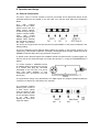
8.1 External Connections
Project Hammerfall consists of the main PCI board and an Expansion Board. All the
essential electronics are located on the PCI card, so it will also work without the Expansion
Board.
The
main
board's
bracket has two ADAT
optical inputs and two
ADAT optical outputs,
as well as a 9-pin D-type
socket. Coaxial S/PDIF
input
and
output
requires plugging in the
adapter cable, whereby
the red phono socket is
the output. The ADAT1
I/O next to the D-type socket can also be used for optical SPDIF, if this mode is selected in the
Settings dialog.
An input is selected via the Settings dialog (started by clicking on the hammer symbol in the
system tray). Hammerfall accepts the commonly used digital audio formats, SPDIF as well as
AES/EBU. Channel status and copy protection are ignored.
In SPDIF mode, identical signals are available at both the optical and the coaxial outputs. An
obvious use for this would be simply connecting two devices, i.e. using the DIGI9652 as a
splitter.
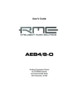
To receive signals in AES/EBU format,
an adapter cable is required. Pins 2 and 3
of a female XLR plug are connected
individually to the two pins of a phono
plug. The cable shielding is only
connected to pin 1 of the XLR - not to the
phono plug.
The ground-free design using transformers for digital inputs and outputs enables trouble-free
connection to all devices, and perfect hum rejection.
The Expansion Board's
bracket gives access to
a third ADAT optical
input and output as well
as word clock I/O. Next
to the two BNC sockets
is an LED, which
displays the word clock
input lock status.
User’s Guide DIGI9652 © RME
7
8.2 Internal Connections
The internal digital input (connector ST3 on the circuit board, CD IN) can be connected to the
digital output of an internal CD-ROM drive. This allows for a direct transfer of digital audio data
within the computer.
Since board revision 1.5 it also allows to use an AEBx-I, when a 3-wire cable connects ST7 on
both AEBx-I and Hammerfall.
Additionally board revision 1.5/1.6 offers two internal outputs, labeled ADAT1OUT (ST5) und
ADAT2OUT (ST9). These can be used to operate one AEBx-O each, for a maximum of 16
analog outputs. The audio data are the same as on the corresponding optical output.
User’s Guide DIGI9652 © RME
8
8.3 Windows MME Playback
The Hammerfall can play back audio data only in supported formats (sample rate, bit
resolution). Otherwise an error message appears (for example at 22 kHz and 8 bit).
In the audio application being used, DIGI9652 must be selected as output device. This can
often be found in the Options, Preferences or Settings menus under Playback Device, Audio
Devices, Audio etc. We recommend using 24-bit resolution for playback, to make full use of the
DIGI9652’s potential.
We strongly recommend switching all system sounds off (via >Control Panel /Sounds<). Also
Hammerfall should not be the Preferred Device for playback, as this could cause loss of
synchronization and unwanted noises. If you feel you cannot do without system sounds, you
should consider buying a cheap Blaster clone and select this as Preferred Device in >Control
Panel /Multimedia /Audio<.
The RME Driver CD includes step by step instructions for configuring many popular audio
applications, found in the directory \rmeaudio.web\english\techinfo\conf.
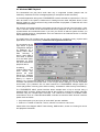
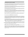
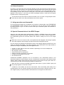
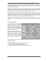
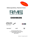
The screenshot to the
right shows a typical
configuration dialogue
as displayed by a
(stereo) wave editor.
After
selecting
a
device, audio data is
sent either to S/PDIF
or to the ADAT ports,
depending on which
has been selected as
playback device.
Increasing
the
number and/or size of
audio buffers may
prevent the audio
signal from breaking
up, but also increases
latency i.e. output is
delayed. For synchronized playback of audio and MIDI (or similar), be sure to activate the
checkbox ‘Get position from audio driver’. Even at higher buffer settings in a mixed Audio/MIDI
environment, sync problems will not arise because the DIGI9652 always reports the
current play position correctly (even while recording - essential for chase lock synchronization).
The DIGI9652 ADAT optical interface allows sample rates of up to 96 kHz using a
standard ADAT recorder. Single-channel data at this frequency requires two ADAT channels,
achieved using the ‘Sample Split’ technique. This reduces the number of available ADAT
channels from 24 to 12. Under Windows MME, channels are routed to ADAT devices in doublespeed mode as follows:
• Only stereo pairs (1+2) and (3+4) of each ADAT port are available
• Channel 1 is routed to channels 1 and 2, channel 2 is routed to 3 and 4 etc.
Please refer to the diagram ‘ADAT Track Routing, MME 96 kHz’, section 21. Routing for record
and playback is identical.
User’s Guide DIGI9652 © RME
9
8.4 Windows MME Recording
Unlike analog soundcards which produce empty wave files (or noise) when no input signal is
present, digital I/O cards always need a valid input signal to start recording.
To take this into account, RME has included two unique features in the DIGI9652: a
comprehensive I/O signal status display (showing sample frequency, lock and sync status) in
the Settings dialogue, and the protective Check Input function.
If a 48 kHz signal is fed to the input and the application is set to 44.1 kHz, Check Input stops
the system from recording. This prevents faulty takes, which often go unnoticed until later on in
the production. Such tracks appear to have the wrong playback rate - the audio quality as such
is not affected.
The sample frequency shown in the Settings dialogue (see chapter 9, screenshot Settings) is
useful as a quick display of the current configuration (the board itself and all connected external
equipment). If no sample frequency is recognized, it will read ‘No Lock’.
With this configuring any suitable audio application for digital recording is simple. After
selecting the required input, DIGI9652 displays the current sample frequency. This
parameter can then be changed in the application’s audio attributes (or similar) dialogue.
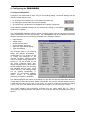
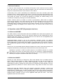
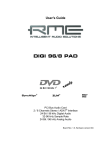
The screenshot to the right shows a typical
dialogue used for changing basic parameters
such as sample frequency and resolution in an
audio application.
Any bit resolution can be selected, providing it is
supported by both the audio hardware and the
software. Even if the input signal is 24 bit, the
application can still be set to record at 16-bit
resolution. The lower 8 bits (and therefore any
signals about 96dB below maximum level) are
lost entirely. On the other hand, there is nothing
to gain from recording a 16-bit signal at 24-bit
resolution - this would only waste precious space
on the hard disk.
It often makes sense to monitor the input signal or send it directly to the output. The
DIGI9652 includes a useful input monitor function for just this purpose (see Monitoring in
the Settings dialog). Activating Record or Pause in the application causes the input signal to be
routed directly to the corresponding output. However, some applications block monitoring by
constantly activating playback, even if the track is empty. This is often required by programs to
ensure that timing and punch I/O will work correctly.
Currently two solutions exist which enable real-time monitoring even when when playback is
active. Our ZLM (Zero Latency Monitoring) technology allows monitoring in Punch I/O mode with this the card behaves like a tape machine. This method has been implemented in all
versions of Samplitude (by SEK’D), and can be activated using the global track option
'Hardware monitoring during Punch'.
The other solution is Steinberg’s ASIO protocol with our ASIO 2.0 drivers and all ASIO 2.0
compatible programs. When 'ASIO Direct Monitoring' has been switched on the input signal is
routed in real-time to the output whenever Record is started.
User’s Guide DIGI9652 © RME
10
8.5 DVD-Playback (AC-3/DTS) under MME
When using popular DVD software player like WinDVD and PowerDVD, their audio data stream
can be send to any AC-3/DTS capable receiver, using the Hammerfall's SPDIF output. For this
to work the SPDIF output wave device has to be selected in 'Control Panel/Sounds and
Multimedia/Audio'. Also check 'use preferred device only'.
You will notice that the DVD software's audio properties now allow to use 'SPDIF Out' or to
'activate SPDIF output'. When selecting these, the software will transfer the non-decoded
digital multichannel data stream using the RME card.
This 'SPDIF' signal sounds like chopped noise at highest level. Therefore check 'Non-audio' in
the card's Settings dialog, to prevent most SPDIF receivers from accepting the signal, and to
prevent any attached equipment from being damaged.
Setting the card to be used as system playback device is against common sense, as
professional cards are not specialized to play back system sounds, and shouldn't be disturbed
by system events. To prevent this, be sure to re-assign this setting after usage, or to disable
any system sounds (tab Sounds, scheme 'No audio').
Note: The DVD player will be synced backwards from the RME card. This means when using
AutoSync and/or word clock, the playback speed and pitch follows the incoming clock signal.
8.6 Low Latency under MME (Buffer Size Adjustment)
Using Windows 95 or 98 the MME buffer size was nothing to worry about. Latencies below 46
ms were not possible. Meanwhile both computers and operating system have become much
more powerful, and since Windows ME/2000/XP latencies far lower can be used. SAWStudio
and Sonar allowed to use such low settings from the start. Sequoia was updated in version
5.91, WaveLab in version 3.04.
In the Hammerfall's Settings dialog the MME buffersize (in fact the DMA buffer size) is set with
the same buttons as the ASIO buffer size. Our test computers allow to use settings down to 64
samples without clicks. Please note that this setting only defines the buffer size of the
hardware. The true and effective latency is configured within the MME application!
Attention: the DMA buffers must not be larger than the application's buffers. This case can
happen unnoticed when using ASIO and MME at the same time (multi-client) and setting
ASIO to 186 ms, while the buffers in the MME application are still set for a lower latency.
Playback will be stuttering and audio will be distorted.
Example: when you set the Hammerfall to 512 you can't use 128 in any program. But setting
DMA to 128 allows to use 128 and all higher values within the software.
Please also note that this is a 'you're welcome to try' feature. We can't guarantee that you will
be able to use 3 or 6 ms with MME. Simply check out by yourself which lowest setting your
system and software allows. Some motherboards with insufficient PCI bandwidth (especially
VIA based) suffer from crackling at settings below 512. Be sure to set the buffer size to 512 or
higher in such a case.
User’s Guide DIGI9652 © RME
11
9. Configuring the DIGI9652
9.1 General Information
Configuring the Hammerfall is done using its own settings dialog. The panel 'Settings' can be
opened in three different ways:
• by clicking on the hammer icon in the Taskbar's system tray
• by starting the 'Hammerfall' link from the Desktop
• via ‘shortcut key’ as defined in the 'Digi9652' link (default: Ctrl-Num2)
Under Windows 2000/XP Settings can be activated by clicking on the DIGI96
symbol in the Taskbar.
The DIGI9652 hardware offers a number of helpful, well thought-of practical functions and
options which affect how the card operates - the DIGI9652 can be configured to suit many
different requirements. The following is available in the 'Settings' dialogue:
•
•
•
•
•
•
Input selection
Output mode
Output channel status
Synchronization behaviour
Input and output status display
Time code display
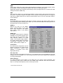
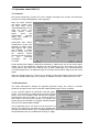
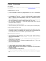
Any changes made in the Settings
dialog are applied immediately confirmation (e.g. by clicking on OK
or exiting the dialogue) is not
required. However, settings should
not be changed during playback or
record if it can be avoided, as this
can cause unwanted noises. Also,
please note that even in 'Stop' mode,
several programs keep the recording
and playback devices open, which
means that any new settings might
not be applied immediately. In
general, we recommend disabling
'Audio
active
in
background’
(assuming this option is available).
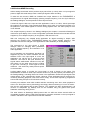
The status displays at the bottom of the dialog box give the user precise information about the
current status of the board, and the status of all signals. ‘SyncCheck’ indicates whether there is
a valid signal for each input (‘Lock’ or ‘No Lock’), or if there is a valid and synchronous signal
(‘Sync’). The ‘Sync Ref’ display shows the input and frequency of the current sync source.
'Time Code' displays time information received from the card’s ADAT Sync In. This is
convenient for checking whether the system is running in time with the transmitting device (e.g.
ADAT).
User’s Guide DIGI9652 © RME
12
MME
Check Input verifies the current input signal against the settings in the record program. When
de-activated a record will always be allowed, even with non-valid input signals.
Monitoring activates the automatic pass-through of the input signal when in record mode. Both
settings are valid for MME only.
AEB
After activating ADAT1 Int. the optical input ADAT1 will be routed to the internal input (CD In).
Then the 4- or 8-channel signal of an AEB-I can be received. The optical input can no longer be
used with an ADAT signal, but can still be used as SPDIF input. For this to work select 'ADAT1'
under 'SPDIF In'.
Buffer Size
The setting Buffer Size determines the latency between incoming and outgoing ASIO* data, as
well as affecting system stability (see chapter 13). Under Windows MME this setting determines
the DMA buffer size (see chapter 8.6).
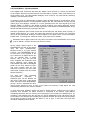
SPDIF In
Defines the input for the SPDIF
signal. 'Coaxial' relates to the white
phono plug, 'Internal' to the jumper
CD In (ST3), 'ADAT1' to the optical
input ADAT1.
SPDIF Out
The SPDIF output signal is constantly
available at the internal jumper Sync
Out (ST4) and the red phono plug.
After selecting 'ADAT1' it is also
routed to the optical output ADAT1.
For further details about the settings
‘Professional’, ‘Emphasis’ and ‘NonAudio’, please refer to chapter 12.
Clock Mode
The card can be configured to use the
following clock sources: external input
signal (AutoSync), internal clock
(Master), or external word clock
signal (Wordclock).
Pref. Sync Ref.
Used to pre-select the desired clock source. If the selected source isn't available the card will
change to the next available one. The currently used clock source and sample rate is displayed
in the SyncRef display.
Status Displays
The status displays at the bottom of the dialog box give various useful information, like
synchronicity of the inputs, sample rate at the SPDIF input, detected Time Code at the ADAT
Sync In, and input and frequency of the current sync source.
* Under W2k/XP also GSIF data
User’s Guide DIGI9652 © RME
13
9.2 Clock Modes - Synchronization
In the digital world, all devices are either the ‘Master’ (clock source) or a ‘Slave’ synchronized
to the master. Whenever several devices are linked within a system, there must always be a
single master clock. The Hammerfall's intelligent clock control is very user-friendly. Selecting
'AutoSync' will activate this mode.
In AutoSync mode, the Hammerfall constantly scans all digital inputs for a valid signal. If this
signal corresponds with the current playback sample rate, the card switches from the internal
quartz (Sync Ref displays 'Internal') to a clock generated from the input signal (Sync Ref
displays 'SPDIF' or 'ADATx'). This allows on-the-fly recording, even during playback, without
having to synchronize the card to the input signal first. It also allows immediate playback at any
sample rate without having to reconfigure the card.
AutoSync guarantees that normal record and record-while-play will always work correctly. In
certain cases however, e.g. when the inputs and outputs of a DAT machine are connected
directly to the Hammerfall, AutoSync causes feedback in the digital carrier, so synchronization
breaks down. To remedy this, switch the card's clock mode over to 'Master'.
Remember that a digital system can only have one master! If the Hammerfall’s clock mode
is set to 'Master', all other devices must be set to ‘Slave’.
All the ADAT optical inputs in the
DIGI9652 as well as the SPDIF
input will work simultaneously.
Because there is no input selector
however, the DIGI9652 has to
be told which of the signals is the
sync reference (a digital device can
only be clocked from a single
source). This is why the card has
been equipped with automatic clock
source selection, which adopts the
first available input with a valid digital
signal as the clock reference input.
The input currently used as sync
reference is shown in the 'Sync Ref'
status field, together with the current
sample frequency.
Via 'Pref Sync Ref' (preferred
synchronization
reference)
a
preferred input can be defined. As
long as the card sees a valid signal
there, this input will be designated as
the sync source, otherwise the other
inputs will be scanned in turn. If none of the inputs are receiving a valid signal, the card
automatically switches clock mode to ‘Master’.
To cope with some situations which may arise in studio practice, setting ‘Pref Sync Ref’ is
essential. One example: An ADAT recorder is connected to the ADAT1 input (ADAT1
immediately becomes the sync source) and a CD player is connected to the S/PDIF input. Try
recording a few samples from the CD and you will be disappointed. Few CD players can be
synchronized. The samples will inevitably be corrupted, because the signal from the CD player
is read with the (wrong) clock from the ADAT i.e. out of sync. In this case, 'Pref Sync Ref'
should be temporarily set to SPDIF.
User’s Guide DIGI9652 © RME
14
If several digital devices are to be used simultaneously in a system, they not only have to
operate with the same sample frequency but also be synchronous with each other. This is why
digital systems always need a single device defined as ‘master’, which sends the same clock
signal to all the other (‘slave’) devices. RME’s exclusive SyncCheck technology, first
implemented in the Hammerfall, enables an easy to use check and display of the current clock
status. The ‘SyncCheck’ field indicates whether no signal (‘No Lock’), a valid signal (‘Lock’) or a
valid and synchronous signal (‘Sync’) is present at each of the three ADAT optical inputs. The
‘Sync Ref’ display shows the current sync source’s input and frequency.
In practice, SyncCheck provides the user with an easy way of checking whether all digital
devices connected to the system are properly configured. With SyncCheck, finally anyone can
master this common source of error, previously one of the most complex issues in the digital
studio world.
An example to illustrate this: The ADAT1 and ADAT2 inputs are receiving signals from a digital
mixing desk that has been set to clock mode 'Internal' or 'Master'. An ADAT recorder is
connected to the ADAT3 input. The DIGI9652 is set to AutoSync mode. As expected,
SyncCheck shows that the ADAT1 and ADAT2 inputs are in sync (as they are driven by the
same clock from the mixing desk), but shows ‘Lock’ instead of 'Sync' for the ADAT3 input.
Because the ADAT
recorder
is
not
receiving any signals
from
Hammerfall or
from the mixer, it will
generate its own
clock at a rate which
is (almost) the same
as
the
sample
frequency of the
mixing desk - but not
identical.
Remedy:
To drive the ADAT
recorder from its
digital input, set it to
slave mode (DIG),
and connect the input to the Hammerfall’s ADAT3 output. Hammerfall is already in
sync with the mixing desk, so it will send an identical (synchronous) signal to ADAT3 out. The
ADAT recorder will lock onto this, its output will also be in sync. The signal from the ADAT
recorder is now fully in sync with the signals from the mixing desk.
Thanks to the its AutoSync technique and a lightning fast PLL, the Hammerfall is not only
capable of handling standard frequencies, but also any sample rate between 25 and 105 kHz.
The input selected in 'Pref Sync Ref' serves as synchronization source. If the Expansion Board
has been installed, and the word clock input is selected (clock mode 'Word Clock'), this will
serve as the synchronization source, allowing any sample frequency between 25 kHz and 56
kHz in varispeed operation.
The current sample frequency at the S/PDIF input (displayed in the ‘SPDIF In’ field) is useful
for troubleshooting and checking the configuration of all connected digital devices. If an input
without a valid signal (or a faulty one) is selected, ‘No Lock’ will appear. In varispeed mode, or
if the sample frequency is way out of tune, ‘Lock’ is displayed.
At 88.2 or 96 kHz: If one of the ADAT inputs has been selected in ‘Pref Sync Ref’, the sample
frequency shown in the ‘SPDIF In’ field differs from the one shown in ‘Sync Ref’. The card
automatically switches to its Sample Split mode here, because ADAT optical inputs and outputs
are only specified up to 48 kHz. Data from/to a single input/output is spread over two channels,
the internal frequency stays at 44.1 or 48 kHz. In such cases, the ADAT sample frequency is
only half the SPDIF frequency.
User’s Guide DIGI9652 © RME
15
10. Word Clock
10.1 Technical Description and Usage
Correct interpretation of digital audio data is dependent upon a definite sample frequency.
Signals can only be correctly processed or transferred between devices if these all share the
same clock, otherwise digital signals are misinterpreted, causing distortion, clicks/crackle and
even dropouts.
AES/EBU, SPDIF and ADAT are self-clocking, so an additional line for word clock could be
considered redundant. In practice however, using several devices at the same time can cause
problems. For example, if devices are connected in a loop without there being a defined
‘master’ device, self-clocking may break down. Besides, the clocks of all devices must be
synchronized from a single source. Devices without SPDIF inputs (typically playback devices
such as CD players) cannot be synchronized via self-clocking.
In digital studios, synchronization requirements can be met by connecting all devices to a
central sync source. For instance, the master device could be a mixing desk, sending a
reference signal - word clock - to all other devices. However, this will only work if all the other
devices have word clock inputs (e.g. some professional CD players) allowing them to run as
slaves. This being the case, all devices will receive the same clock signal, so there is no
fundamental reason for sync problems when they are connected together.
10.2 Cables and Termination
Word clock signals are usually distributed in the form of a network, split with BNC T-adapters
and terminated with resistors. We recommend using off-the-shelf BNC cables to connect all
devices, as this type of cable is used for most computer networks. You will find all the
necessary components (T-adapters, terminators, cables) in most electronics and/or computer
stores.
To avoid voltage loss and reflections, both the cable itself and the terminating resistor should
have an impedance of 75 Ohm. If the voltage is too low, synchronization will fail. High
frequency reflection effects can cause both jitter and sync failure.
In practice, the situation has improved in recent years. The relatively low frequency of word
clock signals is not a problem for modern electronic circuits. Because of the higher voltage,
word clock networks are often more stable and reliable if cables are not terminated at all. Also,
75 Ohm cable is almost impossible to find these days. 50 Ohm cable is standard - this will also
work as long as the termination resistors are 75 Ohm.
The word clock input on Hammerfall’s Expansion Board is a high-impedance type ensuring
maximum flexibility, and is therefore not terminated. If normal termination is necessary (e.g.
because Hammerfall is the last device in the chain), simply connect a T-adapter to its BNC
input jack, connect the cable supplying the word clock signal to one arm of the T-adapter and
terminate the other with a 75 Ohm resistor (as a short BNC plug).
In case the Hammerfall resides within a chain of devices receiving word clock, plug a T-adapter
into Hammerfall’s BNC input jack and the cable supplying the word clock signal to one end
of the adapter (as above), but connect the free end to the next device in the chain via a further
BNC cable. The last device in the chain should be terminated using another T-adapter and a
terminator plug as described in the previous paragraph.
User’s Guide DIGI9652 © RME
16
10.3 General Operation
The green ‘Lock’ LED next to the input jack will light up when the input sees a valid word clock
signal. Selecting ‘Word Clock’ in the ‘Clock Mode’ field will switch clock control over to the word
clock signal. As soon as there is a valid signal at the BNC jack, 'Sync Ref' will display 'Word'.
This message has the same function as the green ‘Lock’ LED next to the BNC input jack, but
appears on the monitor, i.e. the user can check immediately whether a valid word clock signal
is present and is currently being used.
The wordclock input and output as well as all ADAT ports only work in Single Speed mode.
At 96 kHz, the word clock output will therefore be a 48 kHz signal.
11. Using more than one Hammerfall
The current drivers support any combination and number of Hammerfalls, both DIGI9636
and DIGI9652. Please note that only one ADAT Sync can be used (of course). Additional
all cards must be in sync i.e. have to receive valid sync information (either via wordclock or
using AutoSync).
12. Special Characteristics of the SPDIF Output
Apart from the audio data itself, digital signals in SPDIF or AES/EBU format have a header
containing channel status information. False channel status is a common cause of malfunction.
The Hammerfall ignores the received header and creates a totally new one for the output
signal.
Note that in record or monitor modes, set emphasis bits will disappear. Recordings originally
done with emphasis should always be played back with the emphasis bit set!
This can be done by selecting the 'Emphasis' switch in the Settings dialogue ('SPDIF Out'). This
setting is updated immediately, even during playback. The Hammerfall's new output header is
optimized for largest compatibility with other digital devices:
•
•
•
•
•
•
•
32 kHz, 44.1 kHz, 48 kHz, 88.2 kHz or 96 kHz, depending on the current sample rate
Audio use, Non-Audio
No Copyright, Copy Permitted
Format Consumer or Professional
Category General, Generation not indicated
2-channel, No Emphasis or 50/15 µs
Aux bits Audio Use
Professional AES/EBU equipment can be connected to the Hammerfall thanks to the
transformer-balanced coaxial outputs, and the ‘Professional’ format option with doubled output
voltage. Output cables should have the same pinout as those used for input (see section 8.1
‘Connections’), but with a male XLR plug instead of a female one.
Note that most consumer-orientated equipment (with optical or phono S/PDIF inputs) will
only accept signals in ‘Consumer’ format!
The audio bit in the header can be set to 'Non-Audio'. This is necessary when Dolby AC-3
encoded data is sent to external decoders (surround-sound receivers, television sets etc. with
AC-3 digital inputs), as these decoders would otherwise not recognize the data as AC-3.
User’s Guide DIGI9652 © RME
17
13. Operation under ASIO 2.0
13.1 General
We will use Steinberg’s Cubase VST as an example throughout this chapter. All information
provided can easily be adaptated to other programs.
Start the ASIO software
and select ‘System’ from
the Audio menu. Select
'ASIO DIGI9636/52' as the
audio I/O device. The
'ASIO
system
control'
button
opens
the
Hammerfall's
Settings
dialog (see chapter 9,
Configuration).
Hammerfall also allows
simultaneous record and
playback of SPDIF audio
data together with record
and playback in ADAT
format. Please note that
the
external
SPDIF
devices have to be running
in
sync,
otherwise
recordings
will
be
corrupted.
Project Hammerfall supports 'ASIO Direct Monitoring'. Please note that in this mode neither
routing nor pan are supported. Therefore the input signals will only be routed to the same
output channel. Other VST mixer settings have no effect. Additionally, as the Hammerfall has
no internal digital mixer, the playback signal of the ADM channel will be replaced by the record
signal.
When the sample frequency is set to 88.2 or 96 kHz, all the ADAT optical inputs and outputs
operate in Sample Split mode, so the number of available channels is reduced from 24 to 12.
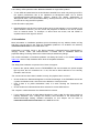
13.2 Performance
The 'Audio Performance' settings are especially important. Firstly, the number of channels
should be changed from 8 to 26 so that all the Hammerfall's inputs can be accessed.
A very common problem is insufficient hard disk performance. If the first track is missing while recording multiple
tracks, or the error message ‘Audio: Record Error’ appears,
the disk sub-system is too slow i.e. it is unable to write the
audio data to the disk quickly enough. The problem can
almost always be remedied by changing ‘Disk Block Buffer
Size’ from the default 64kB to 256kB.
This is especially true if you want to record more than 12
tracks at the same time. 26 tracks are only possible after
changing ‘Disk Block Buffer Size’ to 256kB (depending on your computer). Please note that
these parameters are only updated after clicking on ‘Apply’.
User’s Guide DIGI9652 © RME
18
The heyday of (expensive) SCSI hard disks in high-speed audio workstations is over. Today’s
cheap high-capacity EIDE disks allow continuous transfer rates of well over 10 MByte per
second. In practical terms, this is more than enough to record up to 24 simultaneous tracks
using Cubase and Hammerfall!
However, the hard disks have to work using Busmaster drivers. To activate the EIDE
Busmaster mode in Windows 9x, open the Device Manager (Control Panel/System). Doubleclick on ‘Disk drives’, then on the required hard disk(s). Select ‘DMA’ in the Properties dialog,
then restart Windows. Under Windows 2000/XP busmaster operation is default.
The Buffer Size value in Hammerfall’s Settings dialog determines the latency (in this case the
delay) between the audio application and the Hammerfall as well as general system stability.
The higher the value, the more tracks can be recorded and played back simultaneously and the
longer the system takes to react. At the given maximum of about 0.2 seconds, you will not
notice much delay at all - the system will still respond quickly and smoothly.
Present systems are mostly unable to use the 1.5 ms mode without audible clicks. Current PCs
can handle 3 ms. For optimum reliability we recommend setting the highest latency possible,
186 ms.
13.3 Synchronization
To achieve sample-accuracy between
the ADAT recorder and Hammerfall
while running Cubase, connect the
ADAT sync output with the 9-pin Dtype sync input of the DIGI9652.
The ‘Time Code’ field in the Settings
dialogue should now show the same
position as the ADAT recorder.
Double-clicking on the Sync button in
Cubase’s transport panel will open the
‘Synchronization’ dialogue. Select
ASIO 2.0 as the timecode base (under
Sync Source), confirm the dialogue
with ‘OK’, then activate Sync mode by
(single) clicking on the Sync button.
If synchronization is not working i.e. Cubase does not respond when the ADAT is set to ‘Play’,
please try the following:
•
•
•
•
•
Check the cables
Switch Sync off and on again (in Cubase’s transport panel)
Select ‘Reset Devices’ from the Options menu.
Switch on the ADAT recorder(s) before starting Cubase
Use the BRC as Master and send its word clock to all other devices
User’s Guide DIGI9652 © RME
19
13.4 Known Problems
In case the used computer has no sufficient CPU-power and/or sufficient PCI-bus transfer
rates, then drop outs, crackling and noise will appear. We also recommend to deactivate all
PlugIns to verify that these are not the reason for such effects.
Unfortunately some newer UltraATA66 and UltraATA100 hard disk controller (also Raid
controller) seem to violate against the PCI specs. To achieve the highest throughput they hog
the PCI bus, even in their default setting. Thus when working with low latencies heavy drop
outs (clicks) are heard. Try to solve this problem by changing the default setting of the
controller (for example by reducing the 'PCI Bus Utilization').
Another common source of trouble is incorrect synchronization. ASIO does not support
asynchronous operation, which means that the input and output signals must not only have the
same sample frequency, but they must also be in sync. All devices connected to the
Hammerfall must be properly configured for Full Duplex operation. As long as SyncCheck (in
the Settings dialog) only displays 'Lock' instead of 'Sync', the devices have not been set up
properly!
14. Operation under GSIF (Gigasampler Interface)
14.1 Windows 98/SE/ME
The GSIF interface of the Hammerfall’s Windows 98/SE/ME driver allows direct operation with
Gigasampler and Gigastudio, with up to 26 channels, 96kHz and 24bit. Additionally the driver
supports multi-client operation. For example ASIO can use channels 1/2 and Gigastudio (with
GSIF) channels 3/4 simultaneously, and so on.
Gigasampler/Studio requires a lot of the computer’s calculation power. An optimum
performance is achieved with a stand-alone GSIF PC. If this is not an option we recommend to
set the ASIO latency to the highest value (186ms). This should allow you to achieve a problemfree simultaneous operation of ASIO and GSIF. Gigastudio itself will still work at a very low
latency.
Please note: The Hammerfall requires identical formats when used in multi-client operation! All
programs simultaneously accessing the hardware MUST use the same sample rate.
Simultaneous operation of GSIF and ASIO requires to use different channels. As Cubase
VST always uses tracks 1/2 these tracks must not be activated in Gigastudio/Sampler.
Additionally the tracks activated in Gigastudio/Sampler have to be de-activated in the ASIO
software (for example in the Master Bus section of Cubase).
14.2 Windows 2000/XP
Basically as under Windows 9x. Differences: GSIF under W2k/XP uses a modified interface,
which needs interrupts (similar to ASIO). Therefore the user can now set and change the
latency (under W9x latency was fixed inside Gigastudio). However, when using the
Hammerfall, the latency is always the same as the one selected for ASIO operation. This can
cause performance problems on slower machines when using GSIF and ASIO at the same
time.
Please note that the W2k/XP driver fully supports multi-client operation, including the
combination MME/ASIO. So for example Cubase, Gigastudio and Sonar can be used
simultaneously, provided each of these programs uses its own audio channels exclusively.
Please also note that Gigastudio is running unexpectedly in the background (thus blocking its
assigned audio channels), as soon as the Gigastudio MIDI ports are used – even when
Gigastudio itself hasn't been started.
User’s Guide DIGI9652 © RME
20
15. Hotline - Troubleshooting
15.1 General
The newest information can always be found on our website www.rme-audio.com, section FAQ,
Latest Additions.
The ADAT timecode is not in sync
• The tape is formatted to 48 kHz, but played back at 44.1 kHz (Pitch). This 'Blackface'
problem cannot be solved in a satisfactory way.
ADAT timecode is running, but Cubase does not start 'Play' automatically
• The input displayed in ‘Sync Ref’ is not in sync mode. Sync mode is essential, because
ADAT’s so-called time code is really a sample position, and is therefore only valid for
synchronous audio data.
• Sync is displayed (referring to the card’s clock), but the incoming data is not in sync with the
sample position received at the ADAT Sync In. Then Cubase does not start. Remedy: Set
‘Pref. Sync Ref’ to the input corresponding to the received ADAT Sync signal.
• Sync mode wasn't activated (button in the transport panel), or ASIO 2.0 has not been
chosen as the SMPTE sync source.
The input signal cannot be monitored in real-time
• ASIO Direct Monitoring has not been enabled, and/or monitoring has been disabled globally.
The first 8 channels don’t seem to work
• SPDIF output has been switched to ADAT1. This means that the first ADAT output device,
and therefore the first 8 channels in the ASIO application, are no longer available. All
channels and their assignments still exist, but the optical transmitter has been disconnected
from the ADAT and is now fed from the SPDIF output (channels 25 and 26).
Playback works, but record doesn’t:
• Check that there is a valid signal at the input. If so, the current sample frequency is
displayed in the Settings dialog.
• Check whether the Hammerfall has been selected as recording device in the audio
application.
• Check whether the sample frequency set in the audio application (‘Recording properties’ or
similar) matches the input signal.
• Check that cables/devices have not been connected in a closed loop. If so, set the
systems’s clock mode to ‘Master’.
Crackle during record or playback:
• Increase the number and size of buffers in the ‘Settings’ dialog or in the application.
• Try different cables (coaxial or optical) to rule out any defects here.
• Check that cables/devices have not been connected in a closed loop. If so, set the system’s
clock mode to ‘Master’.
• Increase the buffer size of the hard disk cache.
• Activate Busmaster mode for the hard disks (see section 13.2 'Performance').
• In case of a recently done BIOS update of the motherboard: Propably 'Load BIOS Defaults'
was loaded instead of 'Load Setup Defaults'. This sets the 'PCI Latency Timer' to 0 (default:
32).
User’s Guide DIGI9652 © RME
21
Low Latency ASIO operation under Windows 2000/XP on single CPU systems:
• To use ASIO at lowest latencies under Windows 2000/XP even when only having one CPU,
the system performance has to be optimized for background tasks. Go to Control
Panel/System/Advanced/Performance Options. Change the default 'Applications' to
'Background tasks'. The lowest usable latency will drop from 23 ms to around 3 ms. This is
no issue when using dual CPU systems.
32 kHz files will not play back:
• Hammerfall does not have an internal 32 kHz clock, as this frequency is not covered by the
ADAT standard. However, you can record and playback via SPDIF if the card is clocked
from an external device i.e. AutoSync or Word Clock are active, and fed SPDIF or
equivalent word clock signal is 32 kHz.
15.2 Installation
More information on installation problems (which fortunately are very seldom, thanks to Plug
and Play), can be found in the Tech Info 'Installation problems'. It is located in the directory
\rmeaudio.web\techinfo on the RME Driver CD.
Hammerfall is normally found in the Device Manager (>Settings/Control Panel/System<),
category 'Sound-, Video- and Gamecontroller'. A double click on 'DIGI9652' starts the
properties dialog. Choosing 'Resources' shows Interrupt and Memory Range.
The newest information on hardware problems can always be found on our website www.rmeaudio.com, section FAQ, Hardware Alert: about incompatible hardware.
The dialog 'New hardware component found’ does not appear:
• Remove the optical cables from the DIGI9652 and check whether the optical outputs
light up when the PC is switched on. If not, the card is either defective or not correctly
inserted in the PCI slot.
The card and drivers have been installed correctly, but playback does not work:
• Check whether the Hammerfall appears in the Device Manager. If the 'DIGI9652’ device has
a yellow exclamation mark, then there is an address or interrupt conflict.
• Even if there is no yellow exclamation mark, it is worth checking the ‘Resources’ tab
anyway.
• Check whether the Hammerfall has been selected as current ASIO device.
The computer crashes whenever the Hammerfall is accessed:
• If your graphics board is an older Matrox Mystique or uses a ‘968’ S3 chip, there could be a
memory allocation error. Change the memory area allocated to the Hammerfall via
/Resources/Change Setting. Detailed information on this subject can be found in
\rmeaudio.web\techinfo\install.htm on the RME Driver CD.
User’s Guide DIGI9652 © RME
22
16. DIGICheck : Analysis, Tests and Measurements using the DIGI9652
The DIGICheck software is a unique utility developed for testing, measuring and analysing
digital audio streams. DIGICheck is a subset of functions included in our well-known DAM-1
(Digital Audio Monitor). DIGICheck is not capable of all the DAM-1 functions, because the latter
uses a built-in DSP for its calculations. By its very nature, DIGICheck uses up processor time,
while the DAM-1 unit will run perfectly in the background.
Although the DIGICheck software is fairly self-explanatory, it still includes a comprehensive
online help. A detailed description of all functions is also available in HTML format (digich.htm,
in the \techinfo directory on the RME Driver CD or from our website). The following is a short
summary of the available functions:
• Level Meter. High precision 24-bit resolution, 2/8/26 channels. Application examples: Peak
level measurement, RMS level measurement, over-detection, phase correlation
measurement, dynamic range and signal-to-noise ratios, RMS to peak difference
(loudness), long term peak measurement, input check.
• Bit Statistics. Shows the true resolution of audio signals as well as errors and DC offset.
• Performance Test. Measures overall system performance (computer + DIGI9652)
• Memory Test. Tests the DIGI hardware and the entire audio data path in the PC
DIGICheck is suitable for any card in the DIGI96 series. However, the Hammerfall does not
support Channel Status data, which is why the Channel Status Display is not available.
To install DIGICheck, go to the \DIGICheck directory on the RME Driver CD and run setup.exe.
Follow the instructions prompted on the screen.
17. Accessories
RME offers several optional components, further increasing the flexibility and usability of the
Hammerfall system. Additionally parts of the Hammerfall, like the special adapter cable, are
available seperately.
Part Number
Description
36003
36004
36006
36007
36008
36009
Optical cable, Toslink, 0.5 m (1.5 ft)
Optical cable, Toslink, 1 m (3.3 ft)
Optical cable, Toslink, 2 m (6.6 ft)
Optical cable, Toslink, 3 m (9.9 ft)
Optical cable, Toslink, 5 m (16.4 ft)
Optical cable, Toslink, 10 m (32.8 ft)
Standard lightpipe with TOSLINK connectors, RME approved quality.
36018
33045
Adapter cable D-sub to D-sub / 2 x phono
Internal flat cable to Expansion Board
31143
31144
31145
31146
31161
31204
Eprom W52-G Board Rev 1.1
Eprom W36-G Board Rev 1.1
Eprom M52-2 Board Rev 1.5/1.6
Eprom M36-2 Board Rev 1.5/1.6
Eprom W52-2 Board Rev 1.5/1.6
Eprom W36-2 Board Rev 1.5/1.6
User’s Guide DIGI9652 © RME
23
18. TECH INFO
See http://www.rme-audio.com/techinfo/index.htm or the directory \rmeaudio.web\techinfo on
the RME Driver CD for more detailed information. At the time of writing, the following Tech Info
is available:
Synchronization II (DIGI96 series)
Digital audio synchronization - technical background and pitfalls.
Installation problems
Problem descriptions and solutions.
Information on driver updates
Lists all changes in the drivers of the Hammerfall series.
Configuring Logic, Samplitude, Cubase, Cakewalk, Sonar and SAWPlus32
Step by step instructions for use with RME cards
DIGICheck: Analysis, tests and measurements with the DIGI96 series
A description of DIGICheck, including technical basics.
ADI-8 Inside
Technical information about the RME ADI-8 (24-bit AD/DA converter).
19. Warranty
Each individual Hammerfall undergoes comprehensive quality control and a complete test in a
PC environment at RME before shipping. This may cause very slight signs of wear on the
contacts (if the card looks like it was used one time before - it was). The usage of high grade
components allows us to offer a full two year warranty. We accept a copy of the sales receipt
as valid warranty legitimation.
RME’s replacement service within this period is handled by the retailer. If you suspect that your
card is faulty, please contact your local retailer. The warranty does not cover damage caused
by improper installation or maltreatment - replacement or repair in such cases can only be
carried out at the owner’s expense.
RME does not accept claims for damages of any kind, especially consequential damage.
Liability is limited to the value of the Hammerfall. The general terms of business drawn up by
Synthax OHG apply at all times.
User’s Guide DIGI9652 © RME
24
20. Appendix
RME news, driver updates and further product information are available on our website:
http://www.rme-audio.com
If you prefer to read the information off-line, you can load a complete copy of the RME website
from the RME Driver CD (in the \rmeaudio.web directory) into your browser.
Trademarks
All trademarks, registered or otherwise, are the property of their respective owners. RME,
DIGI96, SyncAlign, ZLM, SyncCheck and Hammerfall are registered trademarks of RME
Intelligent Audio Solutions. DIGICheck, TotalMix, Intelligent Clock Control and TMS are
trademarks of RME Intelligent Audio Solutions. Alesis and ADAT are registered trademarks of
Alesis Corp. ADAT optical is a trademark of Alesis Corp. Microsoft, Windows 98/SE/ME and
Windows 2000/XP are registered trademarks or trademarks of Microsoft Corp. Apple and
MacOS are registered trademarks of Apple Computer Inc. Steinberg, Cubase and VST are
registered trademarks of Steinberg Media Technologies AG. ASIO is a trademark of Steinberg
Media Technologies AG. emagic and Logic Audio are registered trademarks of emagic Softund Hardware GmbH. Pentium is a registered trademark of Intel Corp.
Copyright Matthias Carstens, 6/2002. Version 2.0
Current driver version: W98: 2.60, NT: 3.86, W2k: 2.02
This manual applies to board rev. 1.5, hardware version 003.
Although the contents of this User’s Guide have been thoroughly checked for errors, RME can not guarantee that it is correct
throughout. RME does not accept responsibility for any misleading or incorrect information within this guide. Lending or
copying any part of the guide or the RME Driver CD, or any commercial exploitation of these media without express written
permission from RME Intelligent Audio Solutions is prohibited. RME reserves the right to change specifications at any time
without notice.
User’s Guide DIGI9652 © RME
25
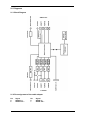
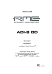
21. Diagrams
21.1 Block Diagram
21.2 Pin assignment of the cable adapter
Pin
9
6
Signal
SPDIF In +
SPDIF Out +
Pin
5
1
Signal
SPDIF In SPDIF Out -
User’s Guide DIGI9652 © RME
26
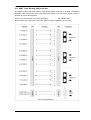
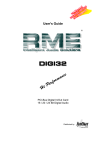
21.3 ADAT Track Routing, ASIO at 96 kHz
This diagram shows the signal paths in ASIO double speed mode (88.2 / 96 kHz). The devices
available under ASIO have been implemented according to the hardware. Signal routing is
identical for record and playback.
Device: The device name in the audio application
SR: Sample Rate
Device name code: Channel in ASIO host, ADAT interface, DIGI9652, card number
User’s Guide DIGI9652 © RME
27
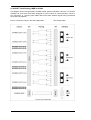
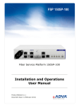
21.4 ADAT Track Routing, MME at 96 kHz
This diagram shows the signal paths in MME double speed mode (88.2 / 96 kHz). The devices
available via wave driver have been designed to avoid conflicts in normal operation, which is
why channels 5, 6, 7 and 8 of each ADAT device have been omitted. Signal routing is identical
for record and playback.
Device: The device name in the audio application
SR: Sample Rate
User’s Guide DIGI9652 © RME
28
22. CE and FCC Compliance Statements
CE
This device has been tested and found to comply with the EN55022 class B and EN50082-1
norms for digital devices, according to the European Council directive on counterpart laws in
the member states relating to electromagnetic compatibility (EMVG).
FCC
This device has been tested and found to comply with the requirements listed in FCC
Regulations, part 15 for Class ‘B’ digital devices. Compliance with these requirements provides
a reasonable level of assurance that your use of this product in a residential environment will
not result in harmful interference with other electronic devices.
This equipment generates radio frequencies and, if not installed and used according to the
instructions in the User’s Guide may cause interference harmful to the operation of other
electronic devices.
Compliance with FCC regulations does not guarantee that interference will not occur in all
installations. If this product is found to be the source of interference, which can be determined
by turning the unit off and on again, please try to eliminate the problem by using one of the
following measures:
• Relocate either this product or the device that is being affected by the interference
• Use power outlets on different branch circuits, or install AC line filters
• Contact your local retailer or any qualified radio and television engineer
When connecting external devices to this product, compliance to limits for a Class ‘B’ device
requires the use of shielded cables.
FCC compliance statement: Tested to comply with FCC standards for home or office use.
User’s Guide DIGI9652 © RME
29