1
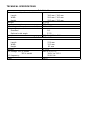
RoboColor II System
users guide
INTRODUCTION 3
HOW TO INSTALL THE ROBOCOLOR II SYSTEM 3
OPERATING WITHOUT A LIGHTING CONTROLLER - STAND ALONE 4
OPERATING STAND ALONE IN MASTER/SLAVE MODE 4
OPERATING WITH A MARTIN LIGHTING CONTROLLER 5
DIP SWITCH SETTINGS FOR THE ROBOCOLOR II SYSTEM 6
TECHNICAL SPECIFICATIONS 7
INTRODUCTION
The RoboColor II is a high performance, intelligent special-effect spotlight which features:
_
_
_
_
_
_
_
_
_
_
_
_
11 dichroic colors, plus white and black-out.
250W/120V ENH lamp.
Color mixing.
Variable speed shutter for strobe effect.
Precision optics with adjustable focus.
Can be controlled by the Martin Controllers: 3032 (512 pcs.), 2032 (128 pcs.), 2208/
2308 (32 pcs.) and 2501 (128 pcs.).
Can be controlled by DMX 512 via the Martin DMX-Interface.
Built-in pre-program or random chases with or without music trig.
Electronic voltage control combined with BIAS option and soft start ensures long lamplife.
High quality stepper motor.
Efficient fan cooling.
Built in overheat thermostat.
HOW TO INSTALL THE ROBOCOLOR II SYSTEM
Basically, a 'RoboColor II System' consists of two different types of components: The
'RoboColor II' units and the 'RoboColor II Controller'. The RoboColor II units are the colorchanging spotlights and the RoboColor II Controller is the "driver" for these spotlights.
You can connect either Two or Four RoboColor II units on one RoboColor II Controller.
WARNING
Do not attempt to operate the RoboColor II units without the RoboColor II Controller
(e.g. plugging the RoboColor II directly into the mains outlet)
as damage might occur to the units.
IMPORTANT
Before attempting any of the following please ensure that the units are
disconnected from any AC power.
_ Remove the 2 finger screws on the top-cover of each RoboColor II unit and carefully
remove the covers. The lamps can now be installed.
_ Replace the top-covers and tighten the screws. You can now install the RoboColor II
units in the desired positions. You are allowed to tilt the units ± 90 degree from horizontal position. Do not turn the units upside down.
_ Plug the RoboColor II power cables into the RoboColor II Controller. If the RoboColor II
Controller is a 220V model there must be at least 2 RoboColor II units plugged in position 1 and 2 or 3 and 4 (the lamps are series connected).
_ Plug the RoboColor II signal cables into the RoboColor II Controller (5 pin DIN plug).
Lengthening these cables or using extension cables is not recommended.
_ Connect the RoboColor II Controller to the mains outlet but do not switch on before
you have set the DIP switch to the desired setting as described in the following chapters.
Note: It is not recommended to pair used lamps together with new ones or to pair lamps
from different manufacturers as electrical variations might shorten the lamp life.
OPERATING WITHOUT A LIGHTING CONTROLLER - STAND ALONE
You can now operate the RoboColor II System in the Stand Alone mode which means
that the RoboColor II units will perform a pre-programmed performance at a pre-set speed
or triggered by sounds picked up by the microphone built into the RoboColor II Controller.
Before switching on the RoboColor II Controller, you will need to set the DIP switch
according to the chosen sequence (program). The sequence settings table on page 6
shows the various DIP switch settings for Stand Alone Sequences. E.g. switching on 1, 2
and 6 will make the RoboColor II System perform 'Demo 1 with music trig'.
Note: Some sequence settings shown on the Sequence Setting table are for service use
only and should not be chosen for light performances.
OPERATING WITH A MARTIN LIGHTING CONTROLLER
The way to get the most out of your RoboColor II System(s) is by controlling via a Martin
Lighting Controller. Because one RoboColor II System, consisting of up to four RoboColor
II units, only requires one controller channel you can control 32 RoboColor II units from
the 8-channel 2308 controller, 128 RoboColor II units from the 32-channel 2032 controller and 512 RoboColor II units from the 128-channel 3032 Controller.
_ Connect the first RoboColor II System to your Martin Lighting Controller (2208/ 2308/
2501/2032/3032) using the XLR/XLR or XLR/DSUB cable which came with the lighting controller.
_If you are using one RoboColor II System only, then insert the male XLR termination
plug, which came with your lighting controller, into the unused XLR socket on the
RoboColor II System.
_If you are using other lighting units (RoboScans, RoboZaps etc.) with the lighting controller they should be connected together with XLR/XLR cables. The last unit on the
link should be terminated with the male XLR termination plug.
_Set the DIP switch on each RoboColor II System to the desired controller channel as
shown in the address setting table on page 6. Make sure that none of the RoboColor
II Systems are set to Stand Alone mode.
_Switch on the RoboColor II Systems before you switch on the lighting controller. A
short start-up and test routine will be performed.
DIP SWITCH SETTINGS FOR THE ROBOCOLOR II SYSTEM
Unit no.
1
2
3
4
5
6
7
8
9
10
11
12
13
14
15
16
Address settings for the RoboColor II System
Unit no.
17
1
18
2
19
1,2
20
3
21
1,3
22
2,3
23
1,2,3
24
4
25
1,4
26
2,4
27
1,2,4
28
3,4
29
1,3,4
30
2,3,4
31
1,2,3,4
32
5
1,5
2,5
1,2,5
3,5
1,3,5
2,3,5
1,2,3,5
4,5
1,4,5
2,4,5
1,2,4,5
3,4,5
1,3,4,5
2,3,4,5
1,2,3,4,5
6
Sequence settings for the RoboColor II System
Description
All switches set to OFF position
Reset
2,6
Demo 1
1,2,6
Demo 1, with music trig
3,6
Demo 2
1,3,6
Demo 2, with music trig
2,3,6
Demo. Random
1,2,3,6
Demo. Random with music trig
4,6
Demo. Random 1
1,4,6
Demo. Random 1 with music trig
2,4,6
Pre-program chase
1,2,4,6
Pre-program chase with music trig
3,4,6
Color sync.
1,3,4,6
Color sync. with music trig
1,3,4,5,6
Mechanical stop (For service use)
3,4,5,6
Adjustment (For service use)
2,4,5,6
L.E.D chase (For service use)
This appendix shows the different address and sequence settings for the DIP switch on
the RoboColor II Controller.
The above settings refer to the pin(s) on the DIP switch which are set to the ON position.
The examples in figure 1 and figure 2, would be described above as; "1" (Unit no. 1).
and; "2,6" (Demo 1).
TECHNICAL SPECIFICATIONS
RoboColor II
Dimensions with/without bracket:
Length
Width
Height
Weight:
Power consumption:
AC-voltage on lamp (recommended):
Beam angle:
Standard
Optional wide angle
Lamp:
RoboColor
Dimensions:
Length
Width
Height
Weight:
AC-voltage: 220 V model
110 V model
AC-frequency:
Fuse
180 mm / 180 mm
200 mm / 160 mm
220 mm / 150 mm
3.0 Kg
250 W
115 V RMS
18°
27.5°
250 W / 120 V ENH
II Controller
276 mm
125 mm
85 mm
2.5 Kg
200 V to 270 V
100 V to 130 V
50-60 Hz
10 AT
PS-941219