1
(6 dB below clipping). If the limiter is switched on, the LED illuminates green to indicate limiter operating threshold has been
reached. The LED will still illuminate red if the preset peak level
is reached before the limiter activation point is reached.
7. Battery Check Switch: When pressed, the status of the two
9V batteries is indicated on the VU meter: an indication in the
red portion of the scale indicates adequate battery power.
When the meter reads 0 VU, the batteries are at about 13.5
volts. A low battery condition is also indicated when the Power–On LED flashes. When using ac power (no batteries in
compartment), the battery check gives no indication.
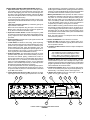
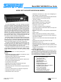
FRONT PANEL CONTROLS AND INDICATORS (Figure 1)
1. Input Gain Control: Adjusts the gain level of each input channel. Rotating the knob counterclockwise reduces gain and
raises the input clipping point. Use a low control setting to handle “hotter” input signals without distortion. With the new M367
input circuit, microphones with a “hot” output can be used without an in-line pad (attenuator).
For best performance, adjust each Input Gain Control so the
associated Input Peak LED illuminates red only on the loudest
signal peaks.
1 kHz Tone Oscillator (Channel 1): Activated by pulling out
Input Channel 1 Gain knob.
Note: Tone level is adjusted using the Input 1 control and the
Master control. Use this tone to send a reference signal level
to any device connected to an M367 output.
2. Input Low-Cut Filter Switch: Provides low–frequency rolloff
to reduce wind noise and rumble. When using the filter, the frequency response is down 7 dB at 150 Hz. Rolloff slope is 6 dB
per octave.
3. Input Peak LED: Illuminates red if input signal reaches 6 dB
below clipping (distortion).
4. Limiter Switch: Activates a fast–acting, peak–responding
limiter. The limiter helps prevent overload distortion from unexpected loud input signals. Limiter action is indicated by the
Output Peak/Limiter LED, which will illuminate green. The
0.1-second release time is optimized for speech signals; an internal modification can provide a 1-second release time for
music signals (see Internal Modifiable Functions).
5. Output Level Meter: The illuminated mechanical VU meter
provides reliable operation and excellent visibility in all environmental and ambient lighting conditions.The meter response approximates true VU characteristics (about 300 ms
rise and fall, 1% to 5 % overshoot). If a slower response is desired, see Internal Modifiable Functions. 0 VU is switchable
between +4 and +8 dBm output level by an externally accessible switch (see Internal Switches and Controls).
An LED array illuminates the meter, eliminating lamp replacement. The meter is illuminated at all times when the mixer is
ac–powered. With dc power, the meter illumination is activated
by the Batt Check switch.
6. Output Peak/Limiter Bi–Color LED: Illuminates red when
output signal reaches a factory preset peak level of +12 dBm
2
3
When the M367 is battery–powered and the switch is pressed
momentarily, the meter illumination turns on for about 10 seconds. Changing meter illumination action to toggled (meter illumination stays on until the switch is pressed again) can be
accomplished via internal DIP switch 6 (see Internal Switches
and Controls for instructions).
Note: The audio signal is not interrupted when the Battery
Check switch is pressed.
8. Power–On/Off Switch: Turns the mixer on and off.
9. Power–On LED: Illuminates green to indicate power is on.
Flashes to indicate low batteries, typically when about 30 minutes of operation remains.
10. Headphones Gain Control: Rotates to adjust headphones
volume level.
WARNING
The headphones circuit is capable of producing
high volume levels that can damage the user’s
hearing. Make sure headphone volume setting
is low (full CCW) before putting headphones on.
Pull/Monitor Switch: When knob is pulled outward, audio signal from Monitor In jack is sent to headphones output, interrupting the program signal to the headphones. If an attenuated
program signal with the monitor signal is desired, refer to the
Internal Switches and Controls section.
11. Headphones Outputs: Stereo 1/4–inch phone jack and stereo 3.5 mm miniature phone jack may be used separately, simultaneously, or as auxiliary feeds to other equipment.
12. Master Gain Control: Sets mixer output gain. Set to 0 dB
position for unity gain output stage.
4
6
5
7
8
9
ÁÁÁ
ÁÁÁÁÁÁÁÁÁÁÁÁÁÁÁÁÁÁÁÁÁÁÁÁÁÁÁÁÁÁÁÁ
Á
ÁÁÁÁÁÁÁÁÁÁÁÁÁÁÁÁÁÁÁ
ÁÁ
Á ÁÁ
ÁÁ ÁÁ
Á
ÁÁ
Á Á
Á Á
Á ÁÁÁ
Á
ÁÁÁÁÁÁÁ
ÁÁ
Á
ÁÁ
Á
ÁÁÁÁÁÁÁÁÁ
ÁÁ
ÁÁÁÁÁÁÁÁ
Á
ÁÁ
Á
ÁÁÁÁÁÁÁÁÁÁÁÁÁÁÁÁÁÁÁÁÁÁÁÁ
ÁÁ
ÁÁ
Á
ÁÁ
Á
ÁÁ
ÁÁ
Á
Á
ÁÁ
ÁÁÁÁÁÁÁÁÁÁÁ
Á
Á
Á
Á
Á
Á
Á
Á
Á
Á
Á
Á
Á
ÁÁ
Á
Á
ÁÁ
Á
Á
Á
Á
Á
Á
Á
Á
Á
Á
ÂÂÂÂÂ
ÂÂ
Á
ÁÁÁÁÁÁÁÁ
Á
Á
Á
Á
Á
Á
Á
ÁÁ
Á
Á
Á
ÁÁ
Á
Á
Á
ÁÁ
Á
Á
Á
ÁÁ
Á
Á
Á
Á
Á
Á
Á
ÁÁ
Á
Á
Á
Á
Á
Á
ÁÁÁÁÁÁ
Á
Á
Á
Á
ÁÁÁÁÁÁÁÁÁÁÁÁÁÁÁÁÁÁÁÁÁÁÁÁÁÁÁÁÁÁÁÁÁÁÁ
ÁÁÁÁÁÁÁÁÁÁÁÁÁÁÁÁÁÁÁ
Á
Á Á Á ÁÁ Á
ÁÁÁÁÁÁÁÁÁÁÁÁ
Á
PEAK
PEAK
PEAK
PEAK
PEAK
PEAK
LIMITER
OUT
5
5
7
3
0
7
3
0
1 10
PULL/1KHz
5
2 10
5
7
3
0
3 10
5
7
3
0
4 10
0
5 10
IN
5
7
3
POWER
7-20
3
0
6 10
1
VU
0
+12
MASTER
M367
12
FRONT PANEL CONTROLS AND INDICATORS
FIGURE 1
2
BATT
PEAK CHECK
ON
PHONES
PULL/MONITOR
11
10