1
Master Gain Remote Control
Note: This modification will disable both the M367’s monitor
function and its front–panel Master gain control,
1. Locate resistor R641 (near Monitor In jack J863) and remove
it.
2. Locate resistor R746 (near Master potentiometer R706) and
remove it.
3. Locate empty pad X702 (near Master potentiometer R706).
Solder one end of a 100 Ω, 1/4 W resistor in the hole of X702.
Solder an insulated wire to the other end of the 100 Ω resistor.
Locate empty pad X644 (near jack J863). Solder the other end
of the insulated wire to X644.
4. Locate empty pad X701 (next to empty pad X702). Solder an
insulated wire to X701. Locate empty pads X645 (near jack
J863). Solder the other end of the insulated wire to the empty
pad X645 nearest channel 6 input connector J856.
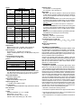
5. Construct a remote control potentiometer/cable assembly as
shown in Figure 7.
DIP Switch S701
Limiter Threshold
Position 2 Position 3
Requiv (above)
—
dBm
—
up
up
high
_____
_____kΩ = R1
down
up
med. high
_____
_____kΩ = R2
up
down
med. low
_____
_____kΩ = R3
down
down
low
_____
_____kΩ = R4
2. Locate resistors R721, R731, R732, R733, R734 and R735
(surrounding IC U704) and remove them.
3. Locate empty pads X732, X733, X734 and X735 (surrounding
IC U704).
4. Select a 1/4 W, 1% resistor closest in value to R1 (from the
worksheet), and solder it to the holes of X732.
Note: Use parallel or series combinations of resistors to match
the chosen values as closely as possible if 1% resistors are not
available.
5. Calculate resistor R5 value as follows:
TIP
1
R5 =
1
R2
RING
CW
MASTER GAIN REMOTE CONTROL
FIGURE 7
Recommended parts are:
Potentiometer, 10–25 kΩ, linear taper (Radio Shack
271–1715)
1/ –Inch Stereo Phone Plug (Switchcraft 280)
4
Ferrite Bead Rings (Ferronics 21–031J)
Capacitors, ceramic, 0.001 µF, 50 V
Cable, 2–conductor, shielded, 50 ft maximum
Ferrite bead rings and capacitors should be as close to the
phone plug as possible.
6. Insert the phone plug in the Monitor In jack. The remote control
potentiometer now controls M367 gain with a control taper
similar to that of the Master gain control.
Changing Limiter Release Time to One Second
1. Locate resistor R741 (about 15 mm behind ribbon cable assembly W813) and remove it.
Changing Limiter Threshold Presets
1. Determine the desired limiter thresholds and select the equivalent resistor values from the following table. Then fill in the
worksheet that follows with the resistor selections.
Requiv (kΩ)
0
18
10
81
1
21
11
93
2
25
12
105
3
30
13
122
4
35
14
139
5
41
15
156
6
47
16
175
7
54
17
194
8
62
18
215
9
71
1
R1
Select a 1/4 W, 1% resistor closest in value to R5 and solder
it to the holes of X733.
SLEEVE
Limiter Threshold
(dBm into 600 Ω)
–
6. Calculate resistor R6 value as follows:
1
R6 =
1
R3
–
1
R1
Select a 1/4 W, 1% resistor closest in value to R6 and solder
it to the holes of X734.
7. Calculate resistor R7 value as follows:
R7 =
1
1
R4
–
1
R1
–
1
R5
–
1
R6
Select a 1/4 W, 1% resistor closest in value to R7 and solder
it to the holes of X735.
An example of limiter threshold preset component calculations
is given in the Appendix.
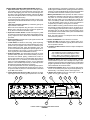
Graphic SymbolsThe M367 rear panel contains graphic symbols with the following meanings (see Figure 8). (A) indicates
the presence of dangerous voltage. (B) indicates that the user
should consult the instruction manual for explanatory material.
(C) indicates that a replacement fuse must be of the same
rating and type.
Limiter Threshold Requiv (kΩ)
(dBm into 600 Ω)
(A)
9
(B)
GRAPHIC SYMBOLS
FIGURE 8
(C)