1
Cable plans
Dimensioning of cable and fuses
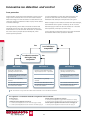
A maximum of one HCW (heating coil) and one CCW/XCU
(cooling) can be connected. The EXact control prevents both
operating at the same time.
The electrician installing the unit is responsible for ensuring
that all sizes used are compatible with current legislation and
regulations.
HCE-type accessories must have a separate power supply.
The VEX340 heat recovery unit has a built-in isolation switch
and automatic fuses for overload and short-circuit protection.
The HCE electric heating coil has a built-in isolation switch
and the control system has short-circuit protection. HCE
internal cables and heating element have short-circuit
protection, via a fuse in the distribution board (not supplied
by EXHAUSTO).
Maximum phase current is the dimensioned current for choice
of cable.
Equalising connections
Equalising connections must be established between the VEX
and HCE-type accessories.
Maximum short circuit current (lcu), in accordance with
EN60947.2 is 10 kA.
Maximum fuse rating is 63 A gG/gL.
Fitting of earth leak circuit breakers
Accessory types HCW, CCW and XCU do not require separate
supply cables and can be directly connected to the VEX340
control system box. Terminals (U1, N) may only be used with
the above mentioned accessories, and can have a maximum
load of 1.8 A.
a) PFI breaker type A, as per EN61008, which breaks the
circuit when leakage-current is registered with DC content
(pulsating DC).
b) Cutout time must be max. 0.3 s.
If earth leak circuit breakers are fitted, they must meet the
following standards:
The current leakage can be up to 300 mA.
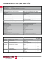
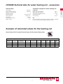
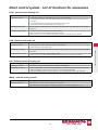
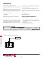
Automatic built in fuses VEX340
Size
VEX340
FC1 = Frequency converter 1
Current
(V)
Fuse for control system
(1 x 230 V) 2 pole
Generel fuse for FC1 and FC2
(1 x 230 V) 2 pole
Total number
of fuses
1 x 230 V + N + PE
10 A
13 A
2
FC2 = Frequency converter 2
VEX340: General
VEX340 without external heating coil
20