1
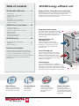
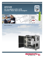
Product information - Version 3 VEX340 Air handling units with counter flow heat exchangers VEX340: 400-2250 m3/h Table of contents VEX340 energy-efficient unit VEX340 (400–2250 m3/h) .............. 4 Highly-efficient counter flow heat exchangers - Technical data ............................................................ 4 - Capacity curves – compact filters ................................ 5 - Temperature efficiency ............................................... 5 - Sound data ................................................................. 6 - Water heating coil / motor valve data ........................ 7 - Cold water coil / motor valve data ............................. 8 - Dimensional sketches ................................................. 9 VEX350/VEX360 units are supplied with highly-efficient counter flow heat exchangers, where airstreams are always 100% separated. The de-icing technology allows continuous operation, even with low outdoor air temperatures. VEX340 EXact Control System ........ 10 - Control and Operation.............................................. 10 - Connection to external units .................................... 11 - Innovative ice detection and control system .............. 12 - Energy calculations ................................................... 13 - Function overview..................................................... 14 - Advanced standard functions.................................... 16 - Technical data, modules ........................................... 17 VEX340 General........................... 18 - Simplified diagrams / Abbreviations .......................... 18 - Cable plans............................................................... 20 - Outdoor installation .................................................. 23 Find more information Technical submission data together with principles for connection of water heating coil / cold water coil can be found on our website under each individual product. The website also allows users to make technical submission calculations and find prices of the complete system and accessories. Integrated control system The control system is integrated in the top of the unit. Control and power supply cables connect to the integrated connection box, which also houses the control fuses and isolation switch. External heating coil/ cold water coil Can be supplied as accessories. An electrical preheating coil is available for installations in areas with low outdoor air temperatures and high extract air humidity levels. Service-friendly unit The unit’s large apertures ensure easy access for servicing and cleaning. The filters, counter flow heat exchanger and motor section can be easily removed for cleaning, servicing and replacing (filters). The door is hinged and removable. Internal bypass The unit have standard built-in modulating bypass for optimal comfort. The bypass circulates the extract air around the counter flow exchanger, depending on the need for heat recovery to maintain the desired supply air temperature, all year round. 3 m 3302 455500 m > 11700<13 3 30 m 2 10 ? e x 10 High efficiency Energy efficient User friendly Online calculation Efficient counter flow heat exchanger delivers optimum efficency of 85 % or more. Low SFP value = lower energy consumption. Control panel with large colour display and user friendly symbols and help texts. User-friendly website for professionals with news, comprehensive documentation and product calculation programmes. 2 - 85% temperature efficiency or greater ..! Two counter flow heat exchangers create a unit that has an extremely high temperature efficiency and low pressure loss. - 80-85% efficiency without condensation - Up to 94% efficiency with condensation Please contact us if you need an extra fast delivery time Cabinet The cabinet is made of Aluzinc® AZ185 corrosion class C4 and is insulated with 50 mm mineral wool. EXstream performance All units are supplied with EXHAUSTOs EXstream fan impeller, - the best of its kind in the market when it comes to high efficiency and low sound levels. EUROVENT certification The EXHAUSTO air handling units in range VEX300 are all EUROVENT certified. The certificate documents that all technical data provided are third party tested by an individual certification body (EXHAUSTO has been tested and verified by TÜV Nord). This, in terms, means that all data provided by the online calculation tools QuickSelect and EXselect has been verified in tests. EUROVENT Energy labelling The EXHAUSTO air handling units type VEX300 are energy labelled according to EUROVENT guidelines for classification of air handling units. The energy class equals the total energy consumption of the unit at given operation parametres. Find more information on our website Fan housing RD12386GB-01 The fans are fitted on rails, for simple removal and servicing. The suspension housing the motor, fan impeller and intake is designed to minimise vibrations. AHU n° 10.12.505 Range: VEX100/200/300 Motor control (FC) The fan motors are controlled by frequency converters which ensures energy-saving operation. dB Hygiene Compact Soundproofed Vibration free The units have been independently certified in accordance with the German standard VDI 6022. The unit can be moved through a standard door (900 x 2,000 mm). Save time and money on soundproofing. Minimum vibration = less noice and no extra resources required to be invested on vibration damping for the base. 3 VEX340 VEX340 Technical data (400–2250 m3 /h) Unit data Absorbed power Max. phase current Power supply 1.8 kW 13.0 A (Power consumption is not sinusoidal) 1 x 230 V + N + PE ~ 50 Hz Principal dimensions, excl. spigots and cable duct. Integrated connection box for control components Panel material Insulation Connection to duct system Service doors (removable) Filters (filter class speci- Compact filter (outdoor air/extract air) fied when ordering) Compact filter (outdoor air/extract air) Height = 1803 mm, Length= 1765 mm, Width = 946 mm Height = 104 mm (see dimensional sketch page 9) Aluzinc AZ185, corrosion class C4 in acc. with EN/ISO 12944-2 50 mm mineral wool ø400 mm 2 side-mounted doors qty. 1 F5 - 6.9 m2, 716 x 836 x 96 mm qty. 1 F7VDI - 21.6 m2, 716 x 836 x 96 mm Weight: Operational-ready unit Weight: Unit for internal transport 450 kg 282 kg (excl. doors, fan unit, bypass section, counter flow heat exchanger and filters) Highly-efficient counter flow heat exchanger with aluminium panels qty. 2 Fan data Fan type Vibration damping EXstream, freely revolving B-impeller Ventilators suspended on vibration dampers With integrated control system 3 x 230 V / 400 V 3 x 2.6 A / 1.5 A 0.55 kW As EFF1 With integrated control system 1 x 230 V 3 x 230 V Built-in Variably adjustable via frequency regulation Motor data (per motor) Voltage supply (delta/star) Current (delta/star) Power rating CEMEP class Frequency converter data Voltage input Voltage output Current overload protection Regulation (not applicable for units for third-party control systems) Accessories in accordance with VDI6022 VEX340OD VEX340 for outdoor installation Special cover and jointing of unit yes HCW340HK Heating coil (water) 6.7 kW Weight: 15.5 kg yes HCE340HK6 Heating coil (electrical) 400 V 6.0 kW, 1 modulating step Weight: 25 kg yes CCW340HK Cold water coil (non-insulated) 9.2 kW Weight: 39 kg CCW340 Cold water coil in 50 mm insulated cabinet 9.2 kW Weight: 72 kg yes CCW340OD Cold water coil in 50 mm insulated cabinet for outdoor fitting 9.2 kW Weight: 72 kg yes 3 x 400 V 12 kW Weight: 9 kg yes PHCE340HK12 Preheating coil (electrical) 4 VEX340 Capacity curves VEX340 VEX340 Capacity curve with F5 filters SFP curve [J/m ] Operating curves A = Pressure loss supplement with F7 filter B = Pressure loss supplement with HCE/HCW C = Pressure loss supplement with CCW Capacity calculations are based on conditions given on our website. To calculate capacity data, use our product calculation software on our website. 3 VEX340 Temperature efficiency Efficiency without condensation according to EN308 Extract air = 25°C/30% RH - Outdoor air = 5°C/50% RH Balance between supply air/extract air = 1.0 Efficiency without condensation with imbalance Extract air = 25°C/30% RH - Outdoor air = 5°C/50% RH Balance between supply air/extract air = 0.8 Efficiency with condensation Extract air = 20°C/55% RH - Outdoor air = -10°C/50% RH Balance between supply air/extract air = 1.0 The VEX unit temperature efficiency is shown at different volume flow ratios, calculated as: ht = t 2.2 - t 2.1 t1.1 - t 2.1 = Temperature efficiency t 2.1 =Temperature of outdoor air Supply air = 0.8 and 1.0 Extract air t 2.2 = Temperature of supply air t1.1 = Temperature of extract air 5 VEX340 Sound data VEX340 LWA1 - Suction side VEX340 VEX340 LWA2 - Pressure side Pressure side (supply air/exhaust air): Suction side (outdoor air/extract air): Surroundings: LW1 = LWA1 + K W LW2 = LWA2 + K W LW3 = LWA3 + KW LWA1 read from graph LWA2 read from graph LWA3 read from graph K W read from table K W read from table KW read from table VEX340 LWA3 - Surroundings KW (dB) LW2 LW3 63 125 250 500 1K 2K 4K 8K I 18 8 -11 1 -12 -20 -25 -32 II 21 11 -1 -2 -11 -21 -27 -21 III 24 14 -6 -8 -17 -24 -21 -14 I -1 -5 -5 -2 -5 -7 -15 -27 II 8 1 4 -6 -6 -8 -18 -23 III 18 8 0 -6 -5 -9 -21 -18 dB(A) I 20 13 1 -6 -8 -12 -17 -21 -15 II 18 12 5 -5 -10 -13 -15 -12 -15 III 13 9 0 3 -10 -12 -11 -9 -15 Sound measurements are based on conditions given on our website. 1,2 2,2 L W2 L W2 1m L pA3 L W1 2,1 1,2 1,1 2,2 L W2 L W2 RD12390-01 L W1 RD12391-01 LW1 KpA Ranges 6 HCW340 Technical data for water heating coil – accessories Calculation example for water heating coil Test pressure Max. operating pressure Number of rows of pipes Number of circuits Face area (HxW) Pipe connection Fin spacing Weight (without fluid) Water content Conditions Water supply temperature Water return temperature Tolerance of calculated results Volume flow ratio Heat recovery 3000 kPa 1600 kPa 1 2 420 x 520 mm DN15 (1/2’’) 1.6 mm 15.5 kg 1.3 l 60 °C 40 °C ± 10 % 1.0 100 % NB: For frost protection using glycol, the output values in the table below must be reduced by approximately 15–20%. Example of calculated values for the heating coil We recommend the heating coil requirements are precisely calculated using the EXselect product selection software tool on our website, which also includes more comprehensive calculation data. VEX340 (2000 m3/h) / HCW340 heating coil (100 % heat recovery) Outdoor air temp./ humidity Room temp./ humidity Temp. and humidity after exchanger HCW output Supply air temp./humidity Water flow [°C / %] [°C / %] [°C / %] [kW] [°C / %] [l/h] -12 / 80 22 / 20 16.0 / 10.0 3.3 22 / 7 144 0.167 0.4 12.97 20 -20 / 85 22 / 20 14.7 / 5.0 4.17 22 / 6.3 183 0.183 0.4 20.84 20 7 p HCW Kvs [kPa] p Kvs [kPa] p air side [Pa] VEX340 Technical data CCW340 technical data for cold water coil – accessories VEX340 Technical Data Test pressure Max. operating pressure Number of rows of pipes Number of circuits Face area (HxW) Pipe connection Fin spacing Weight, non-insulated (without fluid) Weight, insulated model (without fluid) Water content Capacity diagrams for cold water coil 3000 kPa 1600 kPa 4 8 500 x 610 mm DN25 (1’’) 2.8 mm 39 kg 72 kg 3.5 l Conditions Supply water temperature Return water temperature Tolerance of calculated results Volume flow ratio Cooling recovery 6 °C 12 °C ± 10 % 1.0 100 % NB: The output values in the table below are for a glycol content of 25 %. Example of calculated values for the cold water coil We recommend the cold water coil requirements are precisely calculated using the EXselect product selection software tool on our website, which also includes more comprehensive calculation data. VEX340 (2000 m3/h) / CCW340 cold water coil (100 % cooling recovery) Outdoor air temp./ humidity Room temp./ humidity Temp. and humidity after exchanger CCW output Supply air temp./humidity Water flow [°C / %] [°C / %] [°C / %] [kW] [°C / %] [l/h] [kPa] 28 / 50 24 / 50 24.7 / 61 9 16.8 / 84 1399 13.5 2.5 31 40 32 / 40 26 / 50 27.1 / 53 10.6 17.2 / 81 1668 18 2.5 44 40 8 p CCW Kvs p Kvs [kPa] p air side [Pa] VEX340 Dimensioned sketches 62 62 VEX340 Horizontal, Right 17651765 62 62 Left Left 415 415 202 202 1,2 1,2 Exhaust Exhaust air air 62 62 1,2 1,2 Exhaust Exhaust air air N N M M N N 1,1 1,1 Extract Extract air air 2,2 2,2 Supply Supply air air 17651765 168 168 415 415 2,1 2,1 Outdoor Outdoor air air 2,1 2,1 Outdoor Outdoor air air M M 62 62 Right Right 2,2 2,2 Supply Supply air air 1,1 1,1 Extract Extract air air DN15(½") DN15(½") DN15(½") DN15(½") N N M M 946 1) 946 1) Cold water coil (CCW) Non-insulated 1386 1) Allow a distance for service in front of the unit that is equivalent to the unit depth 2) Allow a min. of 200 mm free height for service Cold water coil (CCW) Insulated, Right RD12387GB-01 273 273 RD12387GB-01 604 604 616 626 472 472 200 200 626 Cold water coil (CCW) Insulated, Left 2,2 2,2 O 40 O040 0 616 1,1 1,1 1386 1803 1386 RD12598GB-01 Electric heating coil (HCE) 9 339 339 O 40 O040 0 Heating coil - water (HCW) and electric (HCE) - measured in mm Water heating coil (HCW) O 40 O040 0 472 472 1386 1907 2) 1907 2) 1803 1803 2) 1907 1907 2) RD12598GB-01 626 1386 1803 142 273 273 142 472 472 200 604 604 626 O 40 O040 0 200 1386 616 1386 1,1 1,1 2,2 2,2 O 40 O040 0 1,2 1,2 O 40 O040 0 472 472 339 339 1386 2,1 2,1 2,1 2,1 O 40 O040 0 142 1,2 1,2 O 40 O040 0 N N 1) 1) 946 946 142 M M 616 VEX340 VEX340 Horizontal, Left EXact control system Behind every operation, the advanced EXact control ensures the air handling unit operates as effectively and economically as possible. The control can easily be adjusted to the daily rhythm of the location, whether it is a school, office or residence. VEX340: Control system The essential EXact parameters are: • Simple operation • Three user modes, two which require access codes (technician and specialist) • Several indoor air quality levels with options such as on-demand ventilation via the built-in weekly clock • Built-in web server allows monitoring and control over the internet (TCP/IP) • Can connect to a DDC unit via Modbus RTU as standard and LON options • See several more selected functions in the function overview 3.1.1 Operating settings 23 °C 60 % IAQ. levels > Temp. reg. > Supply air Air reg. > 1 Balance > 1.00 Regulators > Useful help text... 29-05-2009 14:32 HMI control panel The control panel is designed so that it can be operated in two modes, locked or opened. If set in locked mode, the control panel can only be used for normal, daily use, and the user cannot access advanced menus or parameters. User menu The user menu is for daily operations. It shows visual symbols to indicate the unit’s status and provide information. The interface allows the user to temporarily change the temperature and ventilation level. In opened mode, the technician or specialist has access to extra buttons and to more more advanced menus and functions. The control panel requires a code to be operated in open mode. Temperature level/ ventilation level Temperature and ventilation levels can easily and quickly be changed temporarily. Set points are shown together with visual symbols in the display. Alarm/warning The EXact control system will generate a warning symbol if it detects operational disturbances. The display will show an alarm bell if more serious disturbances have been detected. 10 External stop If the ventilation system has been stopped by an external stop signal, this symbol will appear in the display. Support texts The very useful support texts displayed in the yellow area minimise the need for manuals and instructions. Support texts are available in both technician and specialist modes. De-icing If the built-in de-icing function is in operation, this symbol will appear in the display. Connection to external units The EXact control system meets every control requirement for maintaining a perfect indoor climate Web server Internet (TCP/IP) The EXact control system is supplied with a web server (TCP/IP). This enables various options: TCP/IP Modbus Router 1. The unit can be monitored and configured using a local PC. 2. The unit can be connected to a local area network (LAN) and any PC connected to LAN. 3. The unit can be connected to the internet and external internet-enabled PCs. EXHAUSTO Modbus The only requirement is that the connected PC has a browser. The web server is password protected. EXHAUSTO HMI RD12855-01 TCP/IP VEX340: Control system HMI The web server user interface is designed in the same logical fashion as the control panel. Uniformity makes the system easy to use. The overview screen configuration is complete and ready to monitor the ventilation unit and any accessories. Converter Connection to BMS unit Modbus The EXact control system can communicate via standardised Modbus RTU. Thus, a BMS unit that uses Modbus can easily be connected. Modbus MIO EXHAUSTO LON HMI CO2 Connection to other protocols Accessories MLON - Module for converting to LON protocol MTCP - Module for converting to TCP/IP Manual The EXact control system can be operated in manual mode. When operating in manual mode, the hand symbol will appear in the display. Weekly plan When operating with the weekly plan activated, the clock symbol will appear in the display. Overrides When temperature and ventilation level set points are changed, the override symbol will appear in the display while the settings are overridden by the next change in the weekly plan. 11 Summer/winter The Exact control system automatically changes from summer time to winter time. The display indicates either summer time or winter time. RD12204GB-02 BMS Innovative ice detection and control Frost protection To ensure EXHAUSTO counter flow heat exchangers can operate in areas that have low outdoor temperatures EXHAUSTO has developed a unique extract air system. Highly efficient counter flow heat exchangers can be prone to icing as the air extracted from a room can contain moisture. When the energy from this extracted air is used (when the air cools), the moisture condenses to water vapour, which collects in the heat exchanger. When ice begins to form inside the counter flow heat exchanger, the VEX340H control system circulates up to 30 % of the warmed supply air back into the cold outdoor air. This raises the temperature, and helps to prevent icing. VEX340: Control system The high efficiency means that some areas inside the heat exchanger become very cold, and in these areas water will freeze and form ice. This can block the airflow. To counteract this a new control principle has been developed, which ensures optimal operation. Yes Yes Is reduced extraction during de-icing acceptable? METHOD 1 Return air is activated and gradually increased to 30 % To the right side we have the return air principles and below we have the different frost protection methods. Is an imbalance acceptable? No No METHOD 2 Return air is activated and gradually increased to 30 % – if possible Airflows (supply air and extract air) are reduced if necessary to achieve 30 % return air METHOD 3 Return air is activated and gradually increased to 30 % Airflows (supply air and extract air) are reduced if necessary to achieve 30 % return air The outdoor air is gradually reduced The outdoor air is gradually reduced The unit enters hibernation mode The unit enters hibernation mode The unit enters hibernation mode The unit starts every two hours and monitors the situation The unit starts every two hours and monitors the situation The unit starts every two hours and monitors the situation NB! This function is only active for airflow control methods 2 and 5 See below for details. Air regulation - Six different methods of regulation can be selected: Air flow control 2. Constant airflow Constant pressure regulation of supply air 4. Constant pressureregulated supply air with fixed extract air setting 6. Constant pressure regulated supply air with slavecontrolled extract air Constant pressure regulation of extract air 3. Constant pressureregulated extract air with fixed supply air setting 5. Constant pressureregulated extract air with slave-controlled supply air Constant pressure regulation of both extract air and supply air 7. Constant pressure regulation of both extract air and supply air 12 Innovative ice detection and control Return air principle Outdoor air +15°C -6°C 100% +22°C -1°C Extract air 30% 130% +2°C +15°C 100% Fan 2 Fan 1 Supply air Energy calculations Minimal heat loss with VEX340 Ventilation and airing out can be a major source of energy loss from a building. To maintain good indoor air quality it is necessary to continually replace the air, so that moisture and odours can be removed from a room. Heat loss resulting from air replacement is significantly reduced when ventilation units with heat recovery are used. Heat loss is practically zero when the VEX340 is installed. The advantage of counter flow heat exchangers compared to cross-flow heat exchangers is illustrated in the example below, which shows the variable temperature curve for a whole year (24 x 365 = 8760 hours). Conditions: Cross-flow heat exchanger VEX340 counter flow heat exchanger (Temperature) °C 30 (Temperature) °C 30 20 20 10 10 0 0 -10 -10 -20 -20 0 1000 2000 3000 4000 5000 6000 7000 8000 h (hours) Outside temperature Return air temperature Desired supply air temperature Temperature after heat exchanger Recovered heat Heating requirement -30 RD11854GB-01 -30 13 0 RD11853GB-01 RD11852GB-01 Extract air temperature: 22 °C Supply air temperature: 18 °C with equal airflows The blue area shows the given share of recovered heat in the heat exchanger, and the red area shows the need for supplemental heat up to 18 °C (desired supply air temperature), if a heating coil is fitted. Corresponding energy calculations can be done using EXselect, our product selection tool, where conditions such as operating hours, supply/extract air temperatures can be selected. Icing of heat exchanger is not calculated. 1000 2000 3000 4000 5000 6000 7000 8000 h (hours) VEX340: Control system Exhaust air RD12483GB-01 100% EXact control system - List of functions VEX340: Control system The table below describes the control system functions. More detailed descriptions of selected functions are shown on the following pages. Standard Accessory Function / component Description Filter monitor Pressure sensors for monitoring the pressure drop across the filters – alarm for a fall more than the value set and "Early Warnings" Bypass In the case of modulating bypass of extract air, the heat recovery is reduced to maintain the desired supply air temperature Temperature sensors 1) In the extract air spigot to measure/control room temperature 2) In the exhaust air spigot to measure exhaust air temperature 3) In the outdoor air spigot for outdoor air temperature compensation and night-time cooling 4) In the supply air spigot to measure/control supply air temperature 5) Duct temperature sensor 6) Room temperature sensor Overheating protection If there is a danger of the motors or frequency converters overheating the unit will shut off – manual reset. Fire alarm Fire thermostats (40/50/70°C), smoke detector and other fire detection switches can be connected. In the case of a tripped fire alarm, the unit’s functions are adjustable. Closing damper, outdoor air The damper is fitted in the outdoor air duct – it shuts when the unit stops – (requirement for water available with a spring-return motor heating coil) () Closing damper, exhaust air The damper is fitted in the exhaust air duct – it shuts when the unit stops – available with spring-return motor Regulating temperature Regulation of the supply air temperature Regulation of the room temperature Compensation functions Outdoor air temperature compensation Airflow reduction Outdoor airflow compensation Summertime compensation CO2 compensation Humidity compensation Night-time cooling The unit can be set to start at night to cool the building Frost protection Automatic energy-saving feature for preventing icing in the counter flow heat exchanger Control panel Panel for operation at user, technician and specialist level Weekly clock For setting the times required for changes between indoor air quality levels Bus communication Modbus RTU Modbus TCP/IP LONWORKS® Web server Integrated web server allowing control and monitoring over the internet. Cooling recovery On-demand cold recovery Constant pressure regulation Possible for both extract and supply air Motion sensor (PIR) For automatic control of indoor air quality level Airflow measurement Airflow shown in control panel Indoor air quality levels Timer-controlled (comfort, standby, economy, off) Manual Alarm log Displays the last 100 alarms Timers Supply air motor, extract air motor motor Alarm relay Relay for external alarm 14 EXact control system - List of functions for accessories HCW - External water heating coil Function / component Description Temperature sensors 1. In the supply air duct to measure/control supply air temperature 2. On the return pipe from the water heating coil to keep the heating coil warm and protect it from icing 3. To protect external piping linked to the heating coil from icing 4. Temperature sensor on water heating coil supply pipe Modulating motor valve Valve for variably regulating the flow of water to the cold water coil, depending of the cooiling requirement Circulation pump control 1. Control of the water heating coil circulation pump 2. Heat requirement function (keeps heating coil frost-free) 3. Built-in control to run the circulation pump during periods when heating is not required Function / component Description Temperature sensors 1. In the supply air duct to measure supply air temperature 2. In the cold water coil supply pipe Modulating motor valve Valve for variably regulating the flow of water to the cold water coil, depending of the cooiling requirement Circulation pump control 1. Control of the cold water coil circulation pump 2. Built-in control to run the circulation pump during periods when cooling is not required HCE - External electrical heating coil Function / component Description Temperature sensors In the supply air duct to measure/control supply air temperature Overheating protection 1. TSA60 is situated on the circuit board, trips at 60 °C and has manual reset on the HMI panel 2. TSA70 is situated in the air flow, trips at 70 °C and has automatic reset 3. TSA120 is situated in the air flow, trips at 120 °C and has manual reset i HCE and HMI MXCU - External cooling control Function / component Description Temperature sensors In the supply air duct to measure supply air temperature Control of external cooling unit via start/stop signal and on-demand regulation 0–10 V 15 VEX340: Control system CCW - External cold water coil AIRFLOW CONTROL Regulation principles Room temperature or supply air temperature regulation can be selected. The control system regulates temperature using heat/cold recovery and controls external cooling/heating coils or cooling unit if the cooling/heating demand is greater. Regulating room temperature The room temperature is regulated using the unit's built-in temperature sensor in the extract air spigot or an external room/duct sensor. Room temperature summertime compensation is also available. Supply air temperature regulation Supply air temperature is regulated using the unit's built-in temperature sensor in the supply air spigot. Regulating supply air temperature allows for outdoor air compensation. Night-time cooling Comfort can be improved in large-mass buildings (weight) in the summer, by cooling the buildings at night using outdoor air. Night-time cooling is particularly suitable for offices, institutions, etc. where people do not work at night. Extra optimised function. Substantial energy savings in regards to cooling unit. Cooling recovery If there is a need to cool the room or supply air temperature, and the extract air temperature is colder than the outdoor air, cold is recovered from the extract air and used to cool the supply air. Combined with the night-cooling function, this means practically no energy is needed to cool the supply air – as long as the extract air is colder than the supply air. Regulating room temperature – summertime compensation When summertime compensation is selected, the set point for the desired room temperature will increase in line with the outdoor temperature. This avoids an unpleasant cold shock when there is a large difference between indoor and outdoor temperatures, and also saves energy. Outdoor air temperature compensation with supply air temperature regulation Outdoor air compensation is achieved using the unit’s built-in temperature sensor in the outdoor air spigot. When compensating for outdoor air temperature, the supply air temperature set point is lowered in summer and raised in winter. This compensates the supply air temperature in relation to the outdoor air temperature. Outdoor airflow compensation The control system has a built-in function that reduces the airflow when outdoor air temperature falls. The temperature is measured in the outdoor air spigot. Airflow reduction The airflow reduction function can be used when a heating coil is not fitted, or where the heating effect is not sufficient. The supply air is reduced relative to supply air temperature, to maintain the supply air temperature. Airflow control The unit maintains the set airflow. Airflow compensation The airflow is regulated, based on CO2, humidity or temperature measurement. Frost protection when using external water heating coil Frost protection of the water heating coil is achieved using a temperature sensor on the return pipe. If the temperature falls under the set temperature during operation, the unit stops. Heat retention funcIf the unit stops, a heat retention function is activated, which keeps the water in the return tion when using exter- pipe at the set temperature. This minimises the risk of frost in the heating coil and the unit is nal water heating coils ready to start immediately, even when the outdoor temperature is low. SAFETY VEX340: Control system TEMPERATURE EXact control system - Advanced functions Starting the unit On every start-up and before supply air begins, the system warms the heat exchanger with extract air for 30 seconds. Run on with external electric heating coil Electrical heating coils have built-in run on, so that the fans run on at low speed for three minutes after the unit has been stopped. The heating coil is disconnected in that time. Filter monitoring The unit has built-in filter monitoring. Limits are set via the control panel. The control panel will indicate if a filter needs changing and this is registered in the alarm list. Counter flow heat exchanger frost protection Full description available on page 12 16 Technical specifications, modules CONNECTION BOARD MIO (Modbus Input Output) Power supply 24 V DC Analogue input 0-10 V DC ON/OFF 24 V DC Analogue output 0-10 V DC Max. power consumption 0.3 A Digital input 24 V DC BT (fire thermostat/smoke detector) Max. 4 A breaking current Digital output open collector 1 A START/STOP Digital input Relay output 250 V max. 8 A, AC1 Change-over relay. Max 8 A @ 30 V DC or 250 V AC Load Resistance Temperature in NTC 10 kV @ 25 °C Modbus RTU RS-485 Control signal, Analogue Output 0-10 V DC Measurement range 0-2,000 ppm Accuracy +/- 20 ppm @ 25 °C Communication CO2 sensor TCP/IP (Ethernet/webserver) MHCW (Control for water heating coil) MCCW (Control for cold water coil) MXCU (Control for external cooling unit) Humidity sensor Communication Modbus RTU RS-485 Control signal, Analogue Output 0-10 V DC MVM power supply 24 V AC Measurement range 5-95 % RH MVM control signal 0-10 V DC Accuracy +/- 3 % RH (30-70 % RH) PIR sensor 250 V, max. 5 A cos f 0,97 MHCE (Control for electrical heating coil) Communication Modbus RTU RS-485 Number power step Up til 4 Modulating power step Single-step Mains voltage 3 x 400 V + N + PE Perspective, horizontal 90 ° Range 6m Cut-out delay 10 min. TS ROOM E / TS DUCT E Sensor Dimensional sketch - HMI (control panel) NTC 10 kV @ 25 °C Control panel locked mode Control panel open mode Colour graphic display OK OK Operating switches Esc EXHAUSTO RD12248-01 Relay contact for circulation pump VEX340: Control system ALARM EXHAUSTO 17 RD12249-01 2 x LS (Closing damper, exhaust air/outdoor air) Overview of simplified diagram abbreviations. The VEX340 is supplied with components fitted in the unit or for fitting in the duct system and room. The simplified drawing on the next page show components that can be included in a VEX340 air handling unit. Abbreviation The table lists the components for the VEX340. Accessories must be ordered separately. = Standard = Accessory Term VEX340: General BP1 BP2 BT40/50/70 FC1 FC2 HMI LS Damper motor, Bypass Damper motor, Bypass Fire thermostat, 40°C or 50°C and 70°C Frequency converter 1 Frequency converter 2 Control panel Closing damper, exhaust air Closing damper, outdoor air LS (required and supplied with water heating coil) LSR Closing damper (spring return) MVM Motor valve, water heating coil (HCW) M1 Fan motor, 1 M2 Fan motor, 2 MCCW Cold water coil, control system MHCE Electrical heating coil , control system MHCW Water heating coil, control system MIO-CO2-DUCT CO2 sensor, duct MIO-CO2-ROOM CO2 sensor, room MIO-PIR PIR sensor MIO-RH-ROOM Humidity sensor (RH) MIO-TS-DUCT Temperature sensor, extract air duct (external) MIO-TS-ROOM Temperature sensor, room MPT-DUCT Pressure sensor for constant pressure regulation MPT1, P1 Airflow control, extract air MPT1, P2 Filter monitor, extract air MPT2, P1 Airflow control, supply air MPT2, P2 Filter monitor, outdoor air MPT3, P1 Extract airflow control MPT3, P2 Ice detector RAD Motor, extract air damper SUM ALARM Alarm relay TE1,1 Temperature sensor, extract air – spigot 1.1 TE1,2 Temperature sensor, exhaust air– spigot 1.2 TE2,1 Temperature sensor, outdoor air – spigot 2.1 TE2,2 Temperature sensor, supply air – spigot 2.2 TE-RPT Temperature sensor, return pipe from water heating coil (HCW) TE-SPT Temperature sensor, supply TS-RPT-X Temperature sensor, return, external piping (HCW) TSA 60/70/120 Overheating thermostat, 60°C, 70°C and 120°C 18 () VEX340: General Simplified diagram 19 Cable plans Dimensioning of cable and fuses A maximum of one HCW (heating coil) and one CCW/XCU (cooling) can be connected. The EXact control prevents both operating at the same time. The electrician installing the unit is responsible for ensuring that all sizes used are compatible with current legislation and regulations. HCE-type accessories must have a separate power supply. The VEX340 heat recovery unit has a built-in isolation switch and automatic fuses for overload and short-circuit protection. The HCE electric heating coil has a built-in isolation switch and the control system has short-circuit protection. HCE internal cables and heating element have short-circuit protection, via a fuse in the distribution board (not supplied by EXHAUSTO). Maximum phase current is the dimensioned current for choice of cable. Equalising connections Equalising connections must be established between the VEX and HCE-type accessories. Maximum short circuit current (lcu), in accordance with EN60947.2 is 10 kA. Maximum fuse rating is 63 A gG/gL. Fitting of earth leak circuit breakers Accessory types HCW, CCW and XCU do not require separate supply cables and can be directly connected to the VEX340 control system box. Terminals (U1, N) may only be used with the above mentioned accessories, and can have a maximum load of 1.8 A. a) PFI breaker type A, as per EN61008, which breaks the circuit when leakage-current is registered with DC content (pulsating DC). b) Cutout time must be max. 0.3 s. If earth leak circuit breakers are fitted, they must meet the following standards: The current leakage can be up to 300 mA. Automatic built in fuses VEX340 Size VEX340 FC1 = Frequency converter 1 Current (V) Fuse for control system (1 x 230 V) 2 pole Generel fuse for FC1 and FC2 (1 x 230 V) 2 pole Total number of fuses 1 x 230 V + N + PE 10 A 13 A 2 FC2 = Frequency converter 2 VEX340: General VEX340 without external heating coil 20 Cable plans VEX340 with external heating coil - Water heating coil (HCW) / cold water coil (CCW) Size VEX340 Current (V) Dimensioned power consumption (A) (max. phase current) 1 x 230 V + N + PE 13 VEX340: General VEX340 with external heating coil – Electrical (HCE) VEX340 / HCE340 Size Current (V) Dimensioned power consumption (A) (max. phase current) VEX340 1 x 230 V + N + PE 13 HCE340 3 x 400 V + N + PE 8.7 21 VEX340: General Cable plan - Accessories Abbreviation Term ALARM BT40 BT50 BT70 HMI LS LS LSR MCCW MHCE MHCW MIO-CO2 MIO-PIR MIO-RH MIO-TS MPT-DUCT MXCU Smoke detector Alarm relay Overheating thermostat 40 °C Overheating thermostat 50 °C Overheating thermostat 70 °C Control panel Closing damper, exhaust air Closing damper, outdoor air (a requirement of a water heating coil installation) Closing damper, exhaust air/outdoor air (spring return) Cold water coil, automatic Electrical heating coil, automatic Water heating coil, automatic CO2 sensor PIR sensor Humidity sensor (RH) Temperature sensor Pressure sensor for constant pressure control Cooling automatic for control of external cooling system Smoke detector 22 VEX340 - outdoor installation Separate cover for outdoor installation The cabinet is insulated with 50 mm mineral wool and therefore well-suited to outdoor installation. Cover's middle section can open, giving access to the control system. A unit that is installed outdoors is supplied with a fitted cover. The cover is designed so that cables can be led under the cover on both sides, and at the back of the unit. The motor valve, damper and fire thermostats will also be supplied as suitable for outdoor installation. NB: The condenser pipe to the VEX must be frost protected and insulated during installation. Cold water coil can also be used for outdoor fitting. Must be stated on order. VEX340: General We recommend the outdoor unit is fitted with additional support to prevent storm winds from causing imblance. 23 3003601 - 04.2011 - We reserve the right to make changes without notice. EXHAUSTO - indoor air quality makes a difference Technologies System solutions Indoor air quality competences EXHAUSTO provides three technologies within heat recovery, cross-flow heat exchangers, rotary heat exchangers and counter flow heat exchangers. The three technology platforms have their own unique advantages and applications. EXHAUSTO consistently develops system solutions that support professional project planning of ventilation for residences, offices and schools. Every single system meets both regulatory requirements and building owners’ needs and requirements. Our innovation is aimed at energy optimisation in all regards - we develop products that set the standard for future energy requirements. The individual systems are naturally supported by the EXHAUSTO products best suited to each and every installation. EXHAUSTO is part of VKR Holding A/S, incorporated in the company’s ventilation and indoor climate business area. VKR Holding A /S aims to provide customers with innovative and energy-efficient solutions to ensure an excellent indoor climate in new and existing buildings. To read more visit www.vkr-holding.com At EXHAUSTO, we consistently strive to improve the performance of our products, to enhance not only indoor air quality but also the global climate – benefiting everyone. It’s about finding the balance between comfort, energyefficient solutions and economically-viable operating solutions. EXHAUSTO A/S Odensevej 76 DK-5550 Langeskov Tel. +45 65 66 12 34 Fax +45 65 66 11 10 [email protected] www.exhausto-ventilation.com