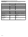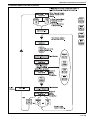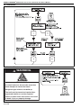
1
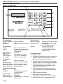
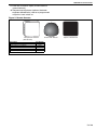
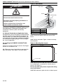
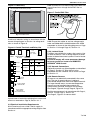
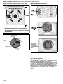
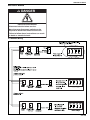
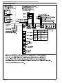
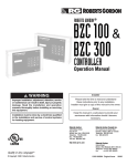
FOR YOUR SAFETY
If you smell gas:
1. Open windows.
2. DO NOT try to light any appliance.
3. DO NOT use electrical switches.
4. DO NOT use any telephone in
your building.
5. Extinguish any open flame.
6. Leave the building.
7. Immediately call your local gas
supplier after leaving the building.
Follow the gas supplier’s
instructions.
8. If you cannot reach your gas
supplier, call the Fire Department.
WARNING
ROBERTS GORDON
®
NRG Control
Energy Saving Control for
ROBERTS GORDON Infrared and
Warm Air Heating Equipment
®
Installation, Operation and Service Manual
Fire Hazard
Keep all flammable objects, liquids and
vapours the minimum required
clearances to combustibles away from
heater.
Some objects will catch fire or explode
when placed close to heater.
Failure to follow these instructions can
result in death, injury or property
damage.
WARNING
Improper installation, adjustment, alteration, service
or maintenance can result in death, injury or
property damage. Read the Installation, Operation
and Service Manual thoroughly before installing or
servicing this equipment.
Installation must be done by an electrician qualified
in the installation and service of control systems
for heating equipment.
© 2014 Roberts-Gordon Europe Limited
Installer
Please take the time to read and understand
these instructions prior to any installation.
Installer must give a copy of this manual to the owner.
Owner
Keep this manual in a safe place in order to provide
your service technician with necessary information.
Roberts-Gordon Europe Limited
Unit A, Kings Hill Business Park
Darlaston Road, Wednesbury
West Midlands, WS10 7SH UK
Telephone: +44 (0)121 506 7700
Fax: +44 (0)121 506 7701
Service Telephone: +44 (0)121 506 7709
Service Fax: +44 (0)121 506 7702
E-mail: [email protected]
E-mail: [email protected]
www.robertsgordon.co.uk
www.blackheatheaters.co.uk
P/N X235 Rev H 07/14
TABLE OF CONTENTS
SECTION 1: Introduction........................................................ 2
1.1 Safety Labels and Their Placement ............................. 2
1.2 What is a ROBERTS GORDON® NRG Control? .......... 2
1.3 General Requirements ................................................. 2
1.4 Control Location ........................................................... 2
1.5 Network Installation...................................................... 2
1.6 Installation Requirements............................................. 3
1.7 Programming Details .................................................... 3
SECTION 2: Specifications .................................................... 4
2.1 Material ........................................................................ 4
2.2 Keypad Layout ............................................................. 4
SECTION 3: Installation.......................................................... 6
3.1 National Standards and Applicable Codes .................. 6
3.2 Installing the ROBERTS GORDON® NRG Control ...... 6
3.3 Electrical Installation Requirements............................. 7
SECTION 4: Wiring.................................................................. 9
4.1 Network Wiring ............................................................ 9
4.2 Low Voltage Wiring .................................................... 10
4.3 CTU Wiring (Pektron Ignition Controller).................... 11
4.4 CTCU Wiring (Pektron Ignition Controller) ................. 11
4.5 CTU Wiring (Pactrol Ignition Controller)..................... 12
4.6 CTCU Wiring (Pactrol Ignition Controller) .................. 12
4.7 Interface Relay Wiring for Multiple Models
CTU 70 - 115 .............................................................. 13
4.8 Interface Relay Wiring for Multiple Models
CTCU 11 - 32 & CTU 40 - 60 ..................................... 14
4.9 MGB/MOB Range Wiring - 1 Ø Cabinet Heaters ....... 15
4.10 MGB/MOB Range Wiring - 3 Ø Cabinet Heaters ..... 16
4.11 Cabinet Heater Remote Lockout Reset Wiring
(With THERMOWATT Ignition Control) .................... 16
4.12 Cabinet Heater Remote Lockout Reset Wiring......... 17
4.13 Unitary Radiant System Wiring ................................ 17
4.14 CORAYVAC® and Multiburner Systems Wiring ........ 18
SECTION 5: Programming and Operation .......................... 19
5.1 Stand Alone Unit........................................................ 19
5.2 Network Unit .............................................................. 19
5.3 System Language ...................................................... 19
5.4 Network Open Level User Functions ......................... 21
5.5 Manager Settings....................................................... 25
5.6 Engineer Settings ...................................................... 31
SECTION 6: Standard Screen Messages ............................ 39
6.1 Stand Alone Control Screen Messages ..................... 39
6.2 Network Control Screen Message ............................. 40
6.3 Fault Messages ......................................................... 40
© 2014 Roberts-Gordon Europe Limited
All rights reserved. No part of this work covered by the copyrights herein may be reproduced
or copied in any form or by any means - graphic, electronic, or mechanical, including
photocopying, recording, taping or information storage and retrieval systems - without the
written permission of Roberts-Gordon Europe Limited.
Printed in U.K.
TABLE OF FIGURES
Figure 1: Keypad Layout ........................................................... 4
Figure 2: Remote Sensors ........................................................ 5
Figure 3: Cover Detail ............................................................... 6
Figure 4: Mounting Hole Layout ................................................ 6
Figure 5: Cable Entry ................................................................ 7
Figure 6: Control Terminals and Relay Use............................... 7
Figure 7: Ferrite EMC Filter ....................................................... 7
Figure 8: Sensor Mounting Plate - Warm Air ............................ 8
Figure 9: Remote Temperature Sensor - Radiant ..................... 8
Figure 10: Sports Hall Sensor ................................................... 8
Product Approval
ROBERTS GORDON® appliances have been tested and CE certified as complying with the
essential requirements of the Gas Appliance Directive, the Low Voltage Directive, the
Electromagnetic Compatibility Directive and the Machinery Directive for use on natural gas, LPG
and fuel oil when installed, commissioned and maintained in accordance with these instructions.
These instructions refer to appliances designed to operate in the European Union.
Appliances designed for other countries (non European Union) are available on request.
This appliance must be installed in accordance with the local and national codes in force and used
only in a sufficiently ventilated space, as specified in these instructions.
Before installation, check that the local gas distribution systems, nature of gas and pressure, and
adjustment of the appliance are compatible.
1 of 40
ROBERTS GORDON® NRG CONTROL INSTALLATION, OPERATION AND SERVICE MANUAL
SECTION 1: INTRODUCTION
Your Safety is Important to Us!
This symbol is used throughout
the manual to notify you of
possible fire, electrical or burn
hazards. Please pay special
attention when reading and following the warnings in these
sections.
Installation, service and annual inspection of
controller must be done by an electrician qualified in
the installation and service of control systems for
heating equipment.
Installation, service and annual inspection of heater
must be done by a contractor qualified in the
installation and service of gas or oil fired heating
equipment.
Read this manual carefully before installation,
operation, or service of this equipment.
The equipment must be applied and operated under
the general concepts of resonable use and installed
using best building practices.
This equipment is not intended for use by persons
(including children) with reduced physical, sensory
or mental capabilities, or lack of experience and
knowledge, unless they have been given
supervision or instruction concerning use of the
appliance by a person responsible for their safety.
Children should be supervised to ensure that they
do not play with the equipment.
For optimum heater performance and safe heating
conditions, inspect and maintain heater(s) before
every heating season and as necessary. Also, know
and maintain heater clearances to combustibles,
see heater Installation, Operation and Service
Manual for further details. If you require additional
manuals, contact Roberts-Gordon at +44 (0)121 506
7700 or at www.robertsgordon.co.uk.
1.1 Safety Labels and Their Placement
Product safety signs or labels should be replaced by
product user when they are no longer legible.
Please contact Roberts-Gordon Europe Limited or
your ROBERTS GORDON® independent distributor
to obtain replacement signs or labels.
1.2 What is a ROBERTS GORDON® NRG
Control?
The ROBERTS GORDON® NRG Control is a micro
processor based controller designed for efficient
control of ROBERTS GORDON® warm air and
radiant products. Each control is intended for
operation of a single zone of heating but is designed
so that individual controls may be linked to form a
network that will allow information and settings to be
available at one or any of the units dependent upon
site configuration. Controls will operate the following
products:
• Warm air heaters On/Off operation
• Unitary BLACKHEAT® radiant systems
2 of 40
• BLACKHEAT® multi burner systems on a single
zone*
• CORAYVAC® systems on a single zone*
• Heaters with two stage High/Low operation
• Heaters with modulating burners requiring a 010V DC input
*For safe use of multiburner and CORAYVAC®systems with up
to four zones operating with a single shared fan, additional use
of ROBERTS GORDON® System Control will be required with a
ROBERTS GORDON® NRG Control installed for each zone.
1.2.1 Features of the ROBERTS GORDON® NRG
Control.
• Coded access to set up and network functions to
prevent unauthorised access.
• Built in temperature sensor.
• Remote temperature sensor option.
• Self learning optimum start.
• Automatic correction for daylight saving time
changes.
• Burner lockout indication and reset for suitable
heater systems.
• Pre programmed holiday functions.
• May be connected on a network to give access
to all controls from a single point.
• Programmed in 5 languages as standard.
• Data logging of hours run and temperatures.
1.3 General Requirements
The ROBERTS GORDON® NRG Control is only for
use with ROBERTS GORDON® heating products.
On site commissioning is required to ensure
temperature sensor is calibrated, and that options
available are selected correctly. Before proceeding
with installation, it will be necessary to check that
the following points have been considered.
1.4 Control Location
Each control is intended to operate a single zone of
heating. The built in sensor may be used for
temperature control. In this case, position control as
in Section 1.6.1 through Section 1.6.3.
When remote temperature sensors are required,
control may be fitted in any suitable location. If
required, two remote sensors may be installed. The
average of the two sensors will be calculated by the
control.
1.5 Network Installation
The ROBERTS GORDON® NRG Control may be
installed on a network so that all controls may be
accessed from a single control, selected controls or
all controls dependent upon how they are configured
on site. To use control on a network simply requires
wiring of COMS port on one control to connect to
COMS port on each of the other controls in a
continuous loop.
SECTION 1: INTRODUCTION
It will then be possible to set program times and
temperatures for all controls from one location and
copy programs from one control to another.
It will also be possible to read the current status of
all controls from a single station.
1.6 Installation Requirements
1.6.1 Radiant Tube Heaters
The ROBERTS GORDON® NRG Control can
operate up to ten burners providing that the
electrical load on each relay does not exceed 7 A
inductive.
Mount ROBERTS GORDON® NRG Control (or
remote sensor if fitted) on a wall or column at a
height of approximately 1.5 to 1.8 metres from the
floor.
The ROBERTS GORDON® NRG Control, or sensor,
should be in a position to monitor an average radiant
temperature. Keep clear of cold draughts, direct
sunlight, direct radiant field heaters and areas of
little air movement such as corners. For larger
systems, use two remote sensors to provide closer
temperature control.
1.6.2 Warm Air Heaters
®
The ROBERTS GORDON NRG Control can
operate a single warm air heater. However up to four
heaters may be controlled from each control if each
heater is provided with interface relays See Page 13,
Section 4.7.
Mount ROBERTS GORDON® NRG Control, or
remote sensor, on a wall or column at a height of
approximately 1.5 to 1.8 metres from floor. The
ROBERTS GORDON® NRG Control, or sensor,
should be positioned where it will monitor an
average room temperature. Keep clear of cold
draughts, direct sunlight, path of warm air from
heater and areas of little air movement such as
corners.
1.6.3 Multiple Unit Considerations
When using control to operate more than one
radiant or warm air heater, careful consideration
should be given to position of control or remote
temperature sensor because single temperature
monitoring point controls all heaters that are
connected. The use of two remote sensors may
provide closer temperature control.
For warm air heaters, the interface relay D 258 must
be installed, in accordance with Page 13, Section
4.7, adjacent to each heater to ensure that the
electrical supply at each heater is isolated for
maintenance.
For larger air heaters, it may not be practical to
operate more than one heater from a single control
due to the larger area covered by these heaters.
length for network is 1,000 m. Keep control cables
away from high current mains circuits to prevent
signal interference.
1.6.5 Electrical Requirements
DANGER
Electrical Shock Hazard
Disconnect electric before service.
Controller must be properly grounded to an
electrical source.
Failure to follow these instructions can
result in death or electrical shock.
The controller must have a 230 V 50 Hz
power supply wired with the Ferrite EMC filter. See
Page 7, Figure 7 in accordance with relevant wiring
diagram from Page 9, Section 4.
1.7 Programming Details
Every control is programmed with default settings
and may be reconfigured to suit the needs of the
installation. See Page 33, Section 5.6.3 and Page
34, Table 1.
When supplied, each ROBERTS GORDON® NRG
Control is configured as a stand alone unit.
Each unit must be configured to operate heating
equipment it is controlling. See Page 33, Section
5.6.3 and Page 34, Table 1.
Programming for stand alone units and network
units is similar. However, for network units, they
must be network configured first. See Page 31,
Section 5.6.1.
Contact Roberts-Gordon Europe Limited for further
advice on control location and application.
1.6.4 Installation Materials
Shielded cable Belden 8451, General Cable C 2514,
or equivalent rated for up to 300 V must be used for
sensors, modulating 0-10 V output, 12 V DC inputs
and network bus connections. Maximum cable
length for each sensor is 100 m. Maximum cable
3 of 40
ROBERTS GORDON® NRG CONTROL INSTALLATION, OPERATION AND SERVICE MANUAL
SECTION 2: SPECIFICATIONS
Figure 1: Keypad Layout
10
1
4
1
®
Quality in Any Language™
7
®
ENTER
NRG Control
RUN
2
3
5
8
0
6
9
SUMMER
DELETE
INFO
2
FAN
PROG
3
COPY
OVER
4
5
RESET
6
UK
USA
WEB
•
•
•
+44 (0)121 506 7700
1.716.852.4400
www.rg-inc.com
DANGER - 230 V 50 Hz
DISCONNECT FROM ELECTRICALSUPPLY
BEFORE REMOVING THIS COVER
9
2.1 Material
2.1.1 Enclosure
Enclosure Material:
Weight:
Dimensions:
2.1.2 Electrical
Supply:
Outputs:
Battery Back Up:
Built in Fuses
Main Fuse:
PCB Protection:
12 V Output:
2.1.3 Sensors
Sensor:
Remote Sensor:
Warm Air & Radiant
Black Bulb Radiant
Sports Hall Sensor
ABS fire retardant
1.6 kg
158 mm x 62 mm x 220 mm
Two Stage Burner
Burner Lockout:
Indication & Reset:
Pressure Switch:
Network:
230 V ± 10% 50 Hz 1 Ø
3 single pole normally open
Rated at 10 A resistive or
7 A inductive.
3 Months.
FS1 800 mA anti-surge
FS2 315 mA quick blow
FS3 315 mA quick blow
Built in as standard
Remote available as option
80 mm x 80 mm x 22 mm
68 mm diameter x 50 mm
Flush Mounting
2.1.4 Program Features
Zones:
One
Programs:
3 timed periods per day,
7 days per week.
Optimum Start:
Selectable
Night Set Back:
Selectable
Burner Modulation: Selectable (0-10 V DC output.
0 V=low fire)
4 of 40
8
7
Selectable
Available for use with suitable
heater types
Connections for fan proving
for CORAYVAC® systems
Up to 32 units may be
connected together on a
network using Belden 8451
shielded cable
2.2 Keypad Layout
1. LCD Readout
2. Run button and fan button, returns to standard
screen from programming options, manual
operation of fan on warm air heaters.
3. Program button and copy button used to enter
program options areas and copy time program.
4. Override button and summer button, used to
allow operating time to be extended and set
control in summer mode.
5. Information button and reset button shows
current setting and status plus burner lockout
reset.
6. Built in temperature sensor.
7. Delete button cancels input during
programming (move forward around network).
8. Numerical key pad for inputting information.
SECTION 2: SPECIFICATIONS
9. Enter key to confirm inputs (move backward
around network).
10.Temperature adjustment (optional, between
engineer defined limits) reverts to programmed
set point at next switch on.
Figure 2: Remote Sensors
Temperature Sensor
Black Bulb Sensor
Sports Hall Sensor
(Wire On Site)
Description
Temperature Sensor (Warm Air & Radiant)
Black Bulb Sensor (Radiant)
Sports Hall Sensor
NRG Controller (not shown)
Interface Relay Assembly (not shown)
Part Number
D247
D269
D270
D268
D258
5 of 40
ROBERTS GORDON® NRG CONTROL INSTALLATION, OPERATION AND SERVICE MANUAL
SECTION 3: INSTALLATION
Figure 3: Cover Detail
DANGER
Clip Cover
Screw
Lid Assembly
Electrical Shock Hazard
Disconnect electric before service.
Controller must be properly grounded to an
electrical source.
Failure to follow these instructions can
result in death or electrical shock.
Installation of ROBERTS GORDON® NRG Control
must be done by an electrician qualified in the
installation of control systems for heating
equipment.
3.1 National Standards and Applicable Codes
All appliances must be installed in accordance with
the latest revision of the applicable standards and
national codes. This refers also to the electric, gas
and venting installation. Note: Additional standards
for installations in public garages, aircraft hangars,
etc. may be applicable.
3.2 Installing the ROBERTS GORDON® NRG
Control
Choose a mounting location for control. See Page 2,
Section 1.4 and Section 1.6.
Description
Clip Cover Plastic
Screw
Lid Assembly
Part Number
10000701
10000700
10010500
3.2.2 Disconnect ribbon cable from control PCB
board.
3.2.3 Position controller. Figure 4 shows mounting
hole locations.
Figure 4: Mounting Hole Layout
175 mm
3.2.1 Remove cover of controller by removing four
clips and screws. See Figure 3 for cover detail.
140 mm
4 x 5 mm dia
3.2.4 Remove plastic cable entry plate and carefully
cut suitable holes as required for conduit entry to
control. See Figure 5.
Do not use other entry routes or pass site wiring
over circuit board.
3.2.5 Refit cable entry plate into slot at side of panel.
6 of 40
SECTION 3: INSTALLATION
3.3.2 Ensure that Live, Neutral and Earth cables are
looped three times through ferrite EMC filter as
shown.
Figure 5: Cable Entry
Removable Plastic Entry Plate
Figure 7: Ferrite EMC Filter
Circuit Board
Cut suitable holes
3.2.6 Install electrical wiring in accordance with the
correct wiring diagram in Section 4 to wiring terminals as shown in Figure 6.
Figure 6: Control Terminals and Relay Use
+
+
+
-
-
1
S
S
2
COMS
PORT
12 V
Override
Press' switch
S
0 -10 V DC
MODULATING REMOTE
OUTPUT
SENSORS
Unitary
Warm Air Radiant
Relay 1
Fan
Relay 2
Burner or
Low Fire
Relay 3
High
Fire
Burner
+
1
2
INPUTS
CRV - Multi
Burner Radiant
Burner
Fan
N.C.
N.O.
Lockout
Reset
C
L
Lockout Signal
230 V 50 Hz
N
N
L
Power Supply
230 V 50 Hz
(From Ferrite Filter)
3.3.3 Ensure that cables to any low voltage equipment are Belden 8451 shielded cables with shield
connected as shown in the wiring diagrams on Page
9, Section 4.1 through Page 10, Section 4.2.
3.3.4 Lockout Reset
Facilities are available for systems that reset to Live
or reset to Neutral. Look at wiring diagram on each
heater to determine correct system to use for heater
concerned.
Failure to comply will cause permanent damage
to burner control on heater and ROBERTS
GORDON® NRG Control.
3.3.5 Network Connections
Optionally controls may linked together as described
on Page 2, Section 1.5. Site wiring is to be
connected and DIP switches set as shown on Page
9, Section 4.1.
3.3.6 Remote Sensors
All sensors are electrically connected in the same
way. The use of remote sensors is optional.
One remote temperature sensor will operate control.
For larger heated areas, two remote temperature
sensors may be installed where control will
automatically calculate average of two readings.
See Page 8, Figure 8 through Page 8, Figure 10.
Position remote sensor/s in accordance with Page 2,
Section 1.4 and Page 3, Section 1.6.
See Page 5, Figure 2 for sensor detail.
3.2.7 Reconnect ribbon cable to PCB board and
replace cover of control by replacing four screws and
covers as removed on Page 6, Section 3.2.1.
3.3 Electrical Installation Requirements
3.3.1 Panel must have a 230 V 50 Hz supply in
accordance with the appropriate wiring diagram from
Section 4.
7 of 40
ROBERTS GORDON® NRG CONTROL INSTALLATION, OPERATION AND SERVICE MANUAL
Figure 8: Sensor Mounting Plate - Warm Air
Figure 10: Sports Hall Sensor
Remote sensors must be fastened using
countersunk screws. Dome headed screws
will short out the board and result in failure
of the sensor.
Figure 9: Remote Temperature Sensor - Radiant
Circuit Board
Screws
Cable
Connections
Cover Screws
Cable Entry
3.3.7 Pressure Switch
For CORAYVAC® systems only, a pressure switch is
required to prove operation of system fan.
This must be connected to input terminals as shown
on Page 10, Section 4.2 and Page 18, Section 4.14
to allow control to monitor correct operation of fan.
Control must also be configured to monitor pressure
switch. See Page 33, Section 5.6.3 and Page 34,
Table 1.
8 of 40
SECTION 4: WIRING
SECTION 4: WIRING
DANGER
Electrical Shock Hazard
Disconnect electric before service.
More than one disconnect switch may be
required to disconnect electric to the unit.
Failure to follow these instructions can result
in death or electrical shock.
4.1 Network Wiring
9 of 40
ROBERTS GORDON® NRG CONTROL INSTALLATION, OPERATION AND SERVICE MANUAL
4.2 Low Voltage Wiring
10 of 40
SECTION 4: WIRING
4.3 CTU Wiring (Pektron Ignition Controller)
4.4 CTCU Wiring (Pektron Ignition Controller)
11 of 40
ROBERTS GORDON® NRG CONTROL INSTALLATION, OPERATION AND SERVICE MANUAL
4.5 CTU Wiring (Pactrol Ignition Controller)
4.6 CTCU Wiring (Pactrol Ignition Controller)
12 of 40
SECTION 4: WIRING
4.7 Interface Relay Wiring for Multiple Models CTU 70 - 115
Description
Interface Relay Assembly
Part Number
D258
13 of 40
ROBERTS GORDON® NRG CONTROL INSTALLATION, OPERATION AND SERVICE MANUAL
4.8 Interface Relay Wiring for Multiple Models CTCU 11 - 32 & CTU 40 - 60
Description
Interface Relay Assembly
14 of 40
Part Number
D258
SECTION 4: WIRING
4.9 MGB/MOB Range Wiring - 1 Ø Cabinet Heaters
15 of 40
ROBERTS GORDON® NRG CONTROL INSTALLATION, OPERATION AND SERVICE MANUAL
4.10 MGB/MOB Range Wiring - 3 Ø Cabinet Heaters
4.11 Cabinet Heater Remote Lockout Reset Wiring (With THERMOWATT Ignition Control)
16 of 40
SECTION 4: WIRING
4.12 Cabinet Heater Remote Lockout Reset Wiring
4.13 Unitary Radiant System Wiring
17 of 40
ROBERTS GORDON® NRG CONTROL INSTALLATION, OPERATION AND SERVICE MANUAL
4.14 CORAYVAC® and Multiburner Systems Wiring
CAUTION
Product Damage Hazard
Do not directly connect control relay terminals
to pump motor.
Failure to follow these instructions can result
in product damage.
18 of 40
SECTION 5: PROGRAMMING AND OPERATION
SECTION 5: PROGRAMMING AND OPERATION
5.1 Stand Alone Unit
The control has three basic levels of operation /
programming.
By default if a control is not connected to a network,
then it assumes stand alone status.
1. Open level where access is open to anyone at
all times. see Page 20, Section 5.3.2.
2. Manager level, where settings may be changed
for normal operation, accessed through the
manager code, which may be changed to one
that can be remembered by the user. See Page
25, Section 5.5.
3. Engineer level where system settings may be
changed and accessed via engineer code,
which is not changeable. See Page 31, Section
5.6.
The following sections break down tasks available
and detail steps to be taken in each level.
SEQUENCE FOR SETTINGS
Set the functions in the order:
1. Set Configuration; Page 33, Section 5.6.3.
2. Calibrate temperature sensor; Page 36, Section 5.6.5.
3. Set optimisation; Page 32, Section 5.6.2.
The remainder of the settings may be undertaken in
any order.
5.2 Network Unit
For network units, all functions of Section 5.1 are
the same. The open level will allow similar functions
on all network controls from a base unit or from any
other network control, dependent on how the
individual units have been site configured. See Page
21, Section 5.4 for options.
Networked units will need to be configured for
network options. See Page 31, Section 5.6.1.
SEQUENCE FOR SETTINGS
1. Configure each control for the network. See
Page 31, Section 5.6.1.
2. Configure each controller for its use with the
engineers code. See Page 31, Section 5.6.
3. Set operational settings with the manager
code. See Page 25, Section 5.5.
Sequences 1 and 2 must be carried out at each
networked station and may be carried out together.
Sequence 3 may be carried out from any "full
control" station for all other stations where operating
times and temperatures may be copied from one
control to another.
5.3 System Language
The ROBERTS GORDON® NRG Control has been
programmed to display in 5 languages.
To select or change the language See Page 19,
Section 5.3.1.
5.3.1 Set System Language
19 of 40
ROBERTS GORDON® NRG CONTROL INSTALLATION, OPERATION AND SERVICE MANUAL
5.3.2 Default Settings
The following settings are factory defaults and will be active following a system reset.
Function
Section
Network Setting
Default Setting
Stand Alone
Network Defaults
Network Access Code
Network Configuration Code
Network ID
Control Name
Network Access
Burner Lockout Reset from
Network
5.6.1
5.6.1
5.6.1
5.6.1
5.6.1
Empty
4143 Fixed
00
Empty
Full
Off
Manager Setting Defaults
Manager Access Code
User Access Code
Daytime Temperature
Night Temperature
Operating Times
5.5.4
5.5.4
5.5.2
5.5.2
5.5.3
0000
0000
20° C
04° C
08:00 17:00 Mon - Fri
OFF Sat - Sun
Engineer Setting Defaults
Engineer Access Code
Optimisation
Rate of Change
Maximum Pre-Heat Hours
Burner Operation
Burner Modulation
Differential
Double Ignition
20 of 40
5.6.2
5.6.3
6343 fixed
On
On 15 minutes / °
02
On/Off
Off
02°
0 OFF (Always Leave OFF)
SECTION 5: PROGRAMMING AND OPERATION
5.4 Network Open Level User Functions
21 of 40
ROBERTS GORDON® NRG CONTROL INSTALLATION, OPERATION AND SERVICE MANUAL
5.4.1 Information
5.4.2 Lockout Reset
WARNING
Explosion Hazard
If control locks out, do not make more than
three attempts to restart the heater.
Dangerous gas mixtures can build up.
The fault must be traced and repaired by a
registered installer or service engineer.
Failure to follow these instructions can result
in death, injury or property damage.
22 of 40
SECTION 5: PROGRAMMING AND OPERATION
5.4.3 Override and Summer Mode
ZONE NAME 20°C
SUMMER
ZONE NAME 20°C
HEAT OFF
PRESS
DEL
OVER
If user code programmed
in engineer set up, then
enter user code.
SUMMER
TO DELETE
WRONG ENTRY
** WARNING! **
If user code not programmed
in engineer set up, then
access to next screen is open.
ENTRY CODE: ????
ENTER
1) OVERRIDE MODE
2) SUMMER MODE
Override allows extra
time on or off outside
of normal program.
1
2
OVERRIDE TO
1) ON
2) OFF
Summer mode turns
heating off.
Standard screen shows
SUMMER MODE. Repeat
selection to cancel.
1= Turns time switch to
on for set extra time.
2= Turns time switch to
off for set extra time.
1
OVERRIDE SETTING
MAXIMUM (04) HRS :00
Pre-set by engineer
If 00 override disabled
Enter extra hours
required i.e. 01
To cancel previous
override, enter 00.
ENTER
23 of 40
ROBERTS GORDON® NRG CONTROL INSTALLATION, OPERATION AND SERVICE MANUAL
5.4.4 Manual Fan Operation
24 of 40
SECTION 5: PROGRAMMING AND OPERATION
5.5 Manager Settings
5.5.1 Manager Network Access
25 of 40
ROBERTS GORDON® NRG CONTROL INSTALLATION, OPERATION AND SERVICE MANUAL
5.5.2 Set Temperature
ZONE NAME 20°C
HEAT OFF
PROG
COPY
Enter manager code
four digits.
Factory default code 0000.
See engineer set up for
alternative access to
manager codes.
** WARNING! **
ENTRY CODE: ????
RUN
Access from network.
See Manager Settings Section
Exit same route.
ENTER
FAN
1) TEMP 2) DATA 3) SYSTEM 4) HOLS
Pres 1-4 for required option.
PRESS
RUN
FAN
1
at any stage to escape.
Repeat press RUN until
return to standard screen.
PRESS
DEL
Enter temp as 2 digits
i.e. 09 for 9
SET DAY PERIOD
TEMP: 18° C
TO DELETE
WRONG ENTRY
ENTER
FROST PROTECTION
1) ON or 2) OFF
1 = Night time (frost)
temperature maintained
during timed off and
holiday periods.
2 = Heating off at all timed
off and holiday periods.
1
SET NIGHT PERIOD
TEMP: 04° C
ENTER
Screen only available
when summer fan
selected in engineer SET SUMMER FAN
set up.
TEMP: 02° C
See Set Fan
Operation
Section.
ENTER
Sets temperature
above setpoint where
fan runs automatically.
26 of 40
2
SECTION 5: PROGRAMMING AND OPERATION
5.5.3 Set Operating Times
Network Control
Stand Alone
Control
ZONE NAME 20°C
HEAT OFF
PROG
COPY
** WARNING! **
Exit to Network
Enter from
Network Control
ENTRY CODE: ????
RUN
ENTER
FAN
1) TEMP 2) DATA 3) SYSTEM 4) HOLS
Pres 1-4 for required option.
RUN
FAN
Return from
Network Control
2
SWITCH TIMES
1) SET 2) COPY
1
Set operating
times from
the Network
Mon Period: 01
S:HH:MM E:HH:MM
2
Copy operating
times from one to
another or all.
Enter manager
code four digits.
Factory default
code 0000.
See engineer
set up for alternative
access to
manager codes.
Note:
When optimum
start set enter
occupancy time.
Warm up period
is automatic.
Enter start time e.g..
08.00
ENTER
ENTER
COPY TIMES
1) ZONE 2) ALL
Enter end time e.g.. 17.00
Mon Period: 02
S:HH:MM E:HH:MM
1
2
Copy times to
all controls.
ENTER
ENTER
Repeat for periods 2 to 3
or leave unwanted periods
empty and press
ENTER
Mon Period: 03
S:HH:MM E:HH:MM
SENDING DATA...
ENTER
Copy times to
individual controls.
Repeat as for Monday
for each day or press
PROG
COPY
ZONE NAME
COPY HERE?
PROG
ENTER
Tue Period: 01
S:HH:MM E:HH:MM
DEL
PROG
Use to move around
network.
COPY
COPY
To repeat
to copy Monday's
program to TUES.
(Flash screen display) Repeat for each day
COPYING ALL DATA required e.g. Tue to Sat.
MON TO TUE
To exit
RUN
FAN
SUN Period: 01
S:HH:MM E:HH:MM
ENTER
e.g. No heat required Sun.
PRESS
RUN
FAN
SUN Period: 02
S:HH:MM E:HH:MM
at any stage to escape.
Repeat press RUN until
return to standard screen.
ENTER
PRESS
DEL
ENTER
SUN Period: 03
S:HH:MM E:HH:MM
TO DELETE
WRONG ENTRY
27 of 40
ROBERTS GORDON® NRG CONTROL INSTALLATION, OPERATION AND SERVICE MANUAL
5.5.4 Set System Time and System Code
28 of 40
SECTION 5: PROGRAMMING AND OPERATION
5.5.5 View Logged Data
29 of 40
ROBERTS GORDON® NRG CONTROL INSTALLATION, OPERATION AND SERVICE MANUAL
5.5.6 Set Holiday Period
Network Control
Stand Alone
Control
ZONE NAME 20°C
HEAT OFF
PROG
COPY
** WARNING! **
ENTRY CODE: ????
RUN
ENTER
FAN
Enter manager code
four digits.
Factory default code 0000.
See engineer set up for
alternatives access to
manager codes.
1) TEMP 2) DATA 3) SYSTEM 4) HOLS
Pres 1-4 for required option.
RUN
FAN
4
HOLIDAYS
1) SET 2) COPY
1
Holiday Period: 01
S:00-00-00 L:00
RUN
ENTER
2
FAN
Enter start date
dd-mm-yy.
eg 25 12 04
press
ENTER
or
COPY HOLS
1) ZONE 2) ALL
Holiday Period: 02
S:00-00-00 L:00
DEL
ENTER
1
to cancel
Enter number of days of
holiday.
ie 02.
2
Holiday Period: 05
S:00-00-00 L:00
RUN
ENTER
ZONE NAME
COPY HERE?
SENDING DATA...
Up to 5 holiday
periods may be
programmed.
PRESS
RUN
FAN
Use
ENTER
PROG
COPY
or
DEL
to move around
network to find
required control.
30 of 40
To copy
to named
control.
at any stage to escape.
Repeat press RUN until
return to standard screen
PRESS
DEL
TO DELETE
WRONG ENTRY
SECTION 5: PROGRAMMING AND OPERATION
5.6 Engineer Settings
All engineer settings must be carried out at individual control.
5.6.1 Network Configuration
31 of 40
ROBERTS GORDON® NRG CONTROL INSTALLATION, OPERATION AND SERVICE MANUAL
5.6.2 Set Override Hours and Optimisation
32 of 40
SECTION 5: PROGRAMMING AND OPERATION
5.6.3 Set Access Code and Configure
33 of 40
ROBERTS GORDON® NRG CONTROL INSTALLATION, OPERATION AND SERVICE MANUAL
Table 1: Recommended Configuration Settings for Appliance Type
Function Type
ON/OFF
Pressure
Screen path from
HI/LO High Flame Boost
Switch
Fan Purge
Double Ignition
Fan Options
engineer code
4-1
4 - 1 - (1)
4-1-(0 or 2)-1 4 - 1 - (0, 1 or 2) 4-1-(0, 1 or 2)
4-2
Burner Options - Warm Air Heaters
ON/OFF
0
N/A
0
0
0
See below
High/Low Operation
1
1
N/A
0
0
See below
Modulating Operation
2
N/A
N/A
0
0
See below
Fan Options - Warm Air Heaters
Constant Fan with Time
1
Burner Options - See Above
Automatic Summer Fan
2
Normal Fan
0 (default)
Radiant Systems
Unitary Tube Heaters
0
N/A
0
0 or 1
0
N/A
Plaque Heaters
0
N/A
0
0 or 1
0
N/A
Linear Tube Heaters
0
N/A
0
0 or 1
0
N/A
®
0
N/A
1
Pre-Purge
00
0
0
N/A
BLACKHEAT
Post-Purge 03
Multiburner Systems
®
0
N/A
1 Pre-Purge 00
0
1
N/A
CORAYVAC Single
Post-Purge 03
Zone Systems
34 of 40
SECTION 5: PROGRAMMING AND OPERATION
5.6.4 Set Fan Operation
35 of 40
ROBERTS GORDON® NRG CONTROL INSTALLATION, OPERATION AND SERVICE MANUAL
5.6.5 Set Sensor Calibration
36 of 40
SECTION 5: PROGRAMMING AND OPERATION
5.6.6 Set Service Mode
37 of 40
ROBERTS GORDON® NRG CONTROL INSTALLATION, OPERATION AND SERVICE MANUAL
5.6.7 System Reset
38 of 40
SECTION 6: STANDARD SCREEN MESSAGES
SECTION 6: STANDARD SCREEN MESSAGES
6.1 Stand Alone Control Screen Messages
39 of 40
ROBERTS GORDON® NRG CONTROL INSTALLATION, OPERATION AND SERVICE MANUAL
6.2 Network Control Screen Message
ZONE NAME 20°C
= This control currently being accessed by another network control.
UNDER NW CONTROL
NETWORK ERROR 01
KEYPAD LOCKED
= This control cannot connect to the network. Check network wiring and
configuration. See Network Wiring Section.
= Network control that has been locked during network configuration.
See Network Configuration Section. No access is allowed at this control.
Use master control to carry out adjustments.
Page 39, Section 6.1 screen messages also apply to network controls.
6.3 Fault Messages
WARNING
Explosion Hazard
If control locks out, do not make more than
three attempts to restart the heater.
Dangerous gas mixtures can build up.
The fault must be traced and repaired by a
registered installer or service engineer.
Failure to follow these instructions can result
in death, injury or property damage.
40 of 40