1
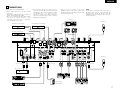
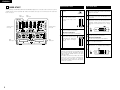
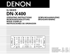
DJ MIXER
DN-X400
OPERATING INSTRUCTIONS
BEDIENUNGSANLEITUNG
MODE D’EMPLOI
INSTRUCCIONES DE OPERACION
GEBRUIKSAANWIJZING
BRUKSANVISNING
L/CUE
LINE1
LINE3
PHONO1/LINE5
PHONO2/LINE7
-20
-15
-10
-7
-5
-3
-1
0
+1
+3
+5
+8
PWR
R/PGM
ON/OFF
10
MIN
LEVEL
MAX
MIN
LINE2
GAIN
MAX
LINE4
GAIN
MIN
MAX
MAX
MIN
LINE6
GAIN
LINE8
GAIN
MASTER
MIC POST
1
2
ON/OFF
+12dB
-26dB
HI
-26dB
10
HI
-12dB
+12dB
6
+10dB
6
BOOTH
/ZONE
4
8
6
6
4
4
2
2
0
0
0
DIGITAL OUT
CUE
CROSS
FADER
START B
TRACK
MARK
CH 1
CH 2
CH 3
AUX MIC
F/S
MONO
F/S
2
3
OFF
4
A
B
1
2
OFF
4
CUE
PGM
PAN
ASSIGN A
CH 4
L-CUE
R-PGM
3
ON
OFF
CH FADER START
CROSSFADER
CONTOUR
MAIN
LOW
LEVEL
1
EFFECT
LOOP
-26dB
ON/OFF
10
10
8
MIC
2
+10dB
0
LOW
CH FADER START
CROSS
FADER
START A
0
MID
-26dB
LOW
CH FADER START
+10dB
2
+10dB
0
-26dB
LOW
6
4
2
+10dB
0
-26dB
LEVEL
-26dB
MID
4
2
+12dB
LOW
+10dB
10
10
METER
8
-26dB
MID
4
+10dB
-12dB
6
0
10
HI
8
-26dB
MID
4
+10dB
-26dB
10
HI
8
-26dB
MAIN MIC
MID
-26dB
10
HI
8
+10dB
3
+10dB
+10dB
+10dB
-12dB
DN-X400
DN-X400
0
ASSIGN B
STEREO
CUE/PGM
0
10
LEVEL
PHONES
FOR ENGLISH READERS
FÜR DEUTSCHE LESER
POUR LES LECTEURS FRANCAIS
PARA LECTORES DE ESPAÑOL
VOOR NEDERLANDSTALIGE LEZERS
FOR SVENSKA LÄSARE
PAGE
SEITE
PAGE
PAGINA
PAGINA
SIDA
15
10
15
20
25
30
~
~
~
~
~
~
PAGE
SEITE
PAGE
PAGINA
PAGINA
SIDA
19
14
19
24
29
34
SAFETY INSTRUCTIONS
CAUTION
RISK OF ELECTRIC SHOCK
DO NOT OPEN
CAUTION: TO
REDUCE THE RISK OF ELECTRIC SHOCK, DO NOT REMOVE COVER (OR
BACK). NO USER SERVICEABLE PARTS INSIDE. REFER SERVICING TO
QUALIFIED SERVICE PESONNEL.
The lightning flash with arrowhead symbol, within an equilateral triangle, is intended to
alert the user to the presence of uninsulated “dangerous voltage” within the product’s
enclosure that may be of sufficient magnitude to constitute a risk of electric shock to
persons.
The exclamation point within an equilateral triangle is intended to alert the user to the
presence of important operating and maintenance (servicing) instructions in the literature
accompanying the appliance.
WARNING:
TO PREVENT FIRE OR SHOCK HAZARD, DO NOT EXPOSE THIS
APPLIANCE TO RAIN OR MOISTURE.
CAUTION:
LABELS:
1. Handle the power supply cord carefully
Do not damage or deform the power supply cord. If it
is damaged or deformed, it may cause electric shock
or malfunction when used. When removing from wall
outlet, be sure to remove by holding the plug
attachment and not by pulling the cord.
2. Do not open the top cover
In order to prevent electric shock, do not open the top
cover.
If problems occur, contact your DENON dealer.
This device complies with Part 15 of the FCC Rules.
Operation is subject to the following two conditions:
(1) This device may not cause harmful interference,
and (2) this device must accept any interference
received, including interference that may cause
undesired operation.
1.
Read Instructions – All the safety and operating
instructions should be read before the appliance is
operated.
11. Grounding or Polarization – Precautions should be taken so
that the grounding or polarization means of an appliance is
not defeated.
2.
Retain Instructions – The safety and operating instructions
should be retained for future reference.
3.
Heed Warnings – All warnings on the appliance and in the
operating instructions should be adhered to.
4.
Follow Instructions – All operating and use instructions
should be followed.
12. Power-Cord Protection – Power-supply cords should be
routed so that they are not likely to be walked on or
pinched by items placed upon or against them, paying
particular attention to cords at plugs, convenience
receptacles, and the point where they exit from the
appliance.
5.
Water and Moisture – The appliance should not be used
near water – for example, near a bathtub, washbowl,
kitchen sink, laundry tub, in a wet basement, or near a
swimming pool, and the like.
6.
6A. An appliance and cart
combination should be
moved with care.
Quick stops, excessive
force, and uneven
surfaces may cause
the appliance and cart
combination to overturn.
Please, record and retain the Model name and serial
number of your set shown on the rating label.
Model No. DN-X400
Serial No.
CAUTION
TO PREVENT ELECTRIC SHOCK, MATCH
WIDE BLADE OF PLUG TO WIDE SLOT,
FULLY INSERT.
17. Nonuse Periods – The power cord of the appliance should
be unplugged from the outlet when left unused for a long
period of time.
8.
Ventilation – The appliance should be situated so that its
location or position does not interfere with its proper
ventilation. For example, the appliance should not be
situated on a bed, sofa, rug, or similar surface that may
block the ventilation openings; or, placed in a built-in
installation, such as a bookcase or cabinet that may
impede the flow of air through the ventilation openings.
18. Object and Liquid Entry – Care should be taken so that
objects do not fall and liquids are not spilled into the
enclosure through openings.
9.
Heat – The appliance should be situated away from heat
sources such as radiators, heat registers, stoves, or other
appliances (including amplifiers) that produce heat.
10. Power Sources – The appliance should be connected to a
power supply only of the type described in the operating
instructions or as marked on the appliance.
FIGURE A
EXAMPLE OF ANTENNA GROUNDING
AS PER NATIONAL
ELECTRICAL CODE
ATTENTION
POUR ÉVITER LES CHOCS ÉLECTRIQUES,
INTERODUIRE LA LAME LA PLUS LARGE
DE LA FICHE DANS LA BORNE
CORRESPONDANTE DE LA PRISE ET
POUSSER JUSQU’ AU FOND.
16. Outdoor Antenna Grounding – If an outside antenna is
connected to the receiver, be sure the antenna system is
grounded so as to provide some protection against voltage
surges and built-up static charges. Article 810 of the
National Electrical Code, ANSI/NFPA 70, provides
information with regard to proper grounding of the mast
and supporting structure, grounding of the lead-in wire to
an antenna-discharge unit, size of grounding conductors,
location of antenna-discharge unit, connection to
grounding electrodes, and requirements for the grounding
electrode. See Figure A.
Wall or Ceiling Mounting – The appliance should be
mounted to a wall or ceiling only as recommended by the
manufacturer.
This Class A digital apparatus meets all requirements
of the Canadian Interference-Causing Equipment
Regulations.
Cet appareil numérique de la classe A respecte toutes
les exigences du Règlement sur le matériel brouilleur
du Canada.
15. Power Lines – An outdoor antenna should be located away
from power lines.
7.
3. Do not place anything inside
Do not place metal objects or spill liquid inside the DJ
mixer.
Electric shock or malfunction may result.
Carts and Stands – The appliance should be used only with
a cart or stand that is recommended by the manufacturer.
14. Cleaning – The appliance should be cleaned only as
recommended by the manufacturer.
ANTENNA
LEAD IN
WIRE
19. Damage Requiring Service – The appliance should be
serviced by qualified service personnel when:
A. The power-supply cord or the plug has been damaged;
or
B. Objects have fallen, or liquid has been spilled into the
appliance; or
C. The appliance has been exposed to rain; or
D. The appliance does not appear to operate normally or
exhibits a marked change in performance; or
E. The appliance has been dropped, or the enclosure
damaged.
20. Servicing – The user should not attempt to service the
appliance beyond that described in the operating
instructions. All other servicing should be referred to
qualified service personnel.
GROUND
CLAMP
ANTENNA
DISCHARGE UNIT
(NEC SECTION 810-20)
ELECTRIC
SERVICE
EQUIPMENT
GROUNDING CONDUCTORS
(NEC SECTION 810-21)
GROUND CLAMPS
POWER SERVICE GROUNDING
ELECTRODE SYSTEM
(NEC ART 250, PART H)
NEC - NATIONAL ELECTRICAL CODE
2
ENGLISH
DEUTSCH
FRANÇAIS
ESPAÑOL
NEDERLANDS
SVENSKA
NOTE ON USE / HINWEISE ZUM GEBRAUCH /
OBSERVATIONS RELATIVES A L’UTILISATION / NOTAS SOBRE EL USO /
ALVORENS TE GEBRUIKEN / OBSERVERA
FRONT PANEL DIAGRAM / VORDERES BEDIENFELD-SCHEMA /
SCHEMA DU PANNEAU AVANT / DIAGRAMA DEL PANEL FRONTAL /
OVERZICHT VAN VOORPANEEL / FRONTPANELEN
482
465
7
1
2
3
11
4
8
8
9
9
7
7
11
11
8
8
9
9
7
13
11
14
17
12
15
28
16
L/CUE
LINE1
LINE3
PHONO1/LINE5
PHONO2/LINE7
-20
ON/OFF
10
MIN
LEVEL
DN-X400
177
101.6
0
-7
MAX
MIN
LINE2
GAIN
MAX
MIN
LINE4
GAIN
MAX
MIN
LINE6
GAIN
MAX
1
2
+10dB
-12dB
ON/OFF
+12dB
-26dB
-12dB
+12dB
6
+10dB
MAIN MIC
MID
+3
BOOTH
/ZONE
+5
+8
CROSS
FADER
START A
10
8
8
6
6
4
4
2
2
0
0
MIC
2
0
CUE
DIGITAL OUT
CROSS
FADER
START B
TRACK
MARK
CH 1
CH 2
CH 3
AUX MIC
F/S
MONO
F/S
3
A
4
1
B
2
PWR
4
PGM
PAN
25
ASSIGN B
24
23
CH 4
L-CUE
R-PGM
3
OFF
CUE
27
MAIN
LOW
LEVEL
2
EFFECT
LOOP
-26dB
LOW
CH FADER START
ON/OFF
10
10
10
LEVEL
METER
6
4
+10dB
0
-26dB
LOW
CH FADER START
0
+10dB
2
+10dB
0
-26dB
LOW
6
4
2
+10dB
0
-26dB
6
10
0
STEREO
CUE/PGM
10
LEVEL
PHONES
23
21
20
19
18
26
26
22
7 x 10 hole
Loch 7 x 10
Trou 7 x 10
Orificio de 7 x 10
Opening 7 x 10
Hål, 7 x 10
REAR PANEL DIAGRAM / HINTERES ANSCHLUSSFELD-SCHEMA /
SCHEMA DU PANNEAU ARRIERE / DIAGRAMA DEL PANEL POSTERIOR /
OVERZICHT VAN ACHTERPANEEL / BAKPANELEN
39
37
30
POWER
REC
OUT
MASTER OUT
BALANCED
39
41
31
R
LINE8
PHONO2/LINE7
LINE6
39
39
CH3
CH4
UNBALANCED
39
41
39
CH2
PHONO1/LINE5
LINE4
CH1
LINE3
LINE2
44
MAIN MIC
LINE1
L
L
L
ON
R
R
L
PH LN
R
PH LN
OFF
SEND
RETURN
R
100Hz
L
SIGNAL GND
40Hz
EFFECT
29
38
BOOTH/ZONE
34
COAXIAL
OPTICAL
DIGITAL OUT
32
33
200Hz
FREQ.
SUB WOOFER
35
FADER
42
42
32
43
58
FADER
AUX MIC
36
105
• The ventilation should not be impeded by covering the ventilation openings with items, such as newspapers, table-cloths,
curtains, etc.
• No naked flame sources, such as lighted candles, should be placed on the apparatus.
• Please be care the environmental aspects of battery disposal.
• The apparatus shall not be exposed to dripping or splashing for use.
• No objects filled with liquids, such as vases, shall be placed on the apparatus.
+1
-26dB
MID
4
2
+12dB
LOW
+10dB
8
-26dB
MID
4
+10dB
-12dB
6
0
10
HI
8
-26dB
MID
-26dB
10
HI
8
-26dB
MID
5
• Do not obstruct the ventilation holes.
• Die Belüftungsöffnungen dürfen nicht
verdeckt werden.
• Ne pas obstruer les trous d’aération.
• No obstruya los orificios de ventilación.
• De ventilatieopeningen mogen niet worden
beblokkeerd.
• Täpp inte till ventilationsöppningarna.
0
4
+10dB
+10dB
-26dB
10
HI
8
+10dB
3
+10dB
-26dB
10
HI
HI
ASSIGN A
✽ (For sets with ventilation holes)
-1
LINE8
GAIN
CROSSFADER
CONTOUR
• Never disassemble or modify the set in any
way.
• Versuchen Sie niemals das Gerät
auseinander zu nehmen oder auf jegliche Art
zu verändern.
• Ne jamais démonter ou modifier l’appareil
d’une manière ou d’une autre.
• Nunca desarme o modifique el equipo de
ninguna manera.
• Nooit dit apparaat demonteren of op andere
wijze modifiëren.
• Ta inte isär apparaten och försök inte bygga
om den.
-3
MASTER
1
• Do not let insecticides, benzene, and thinner
come in contact with the set.
• Lassen Sie das Gerät nicht mit Insektiziden,
Benzin
oder
Verdünnungsmitteln
in
Berührung kommen.
• Ne pas mettre en contact des insecticides,
du benzène et un diluant avec l’appareil.
• No permita el contacto de insecticidas,
gasolina y diluyentes con el equipo.
• Laat geen insektenverdelgende middelen,
benzine of verfverdunner met dit apparaat in
kontakt komen.
• Se till att inte insektsmedel på spraybruk,
bensen och thinner kommer i kontakt med
apparatens hölje.
-5
MIC POST
OFF
CAUTION
3
-10
R/PGM
ON
OFF
CH FADER START
• Unplug the power cord when not using the
set for long periods of time.
• Wenn das Gerät eine längere Zeit nicht
verwendet werden soll, trennen Sie das
Netzkabel vom Netzstecker.
• Débrancher le cordon d’alimentation lorsque
l’appareil n’est pas utilisé pendant de
longues périodes.
• Desconecte el cordón de energía cuando no
utilice el equipo por mucho tiempo.
• Neem altijd het netsnoer uit het stopkontakt
wanneer het apparaat gedurende een lange
periode niet wordt gebruikt.
• Koppla ur nätkabeln om apparaten inte
kommer att användas i lång tid.
• Handle the power cord carefully.
Hold the plug when unplugging the cord.
• Gehen Sie vorsichtig mit dem Netzkabel um.
Halten Sie das Kabel am Stecker, wenn Sie
den Stecker herausziehen.
• Manipuler le cordon d’alimentation avec
précaution.
Tenir la prise lors du débranchement du
cordon.
• Maneje el cordón de energía con cuidado.
Sostenga el enchufe cuando desconecte el
cordón de energía.
• Hanteer het netsnoer voorzichtig.
Houd het snoer bij de stekker vast wanneer
deze moet worden aan- of losgekoppeld.
• Hantera nätkabeln varsamt.
Håll i kabeln när den kopplas från el-uttaget.
-15
DN-X400
• Avoid high temperatures.
Allow for sufficient heat dispersion when
installed on a rack.
• Vermeiden Sie hohe Temperaturen.
Beachten Sie, daß eine ausreichend
Luftzirkulation gewährleistet wird, wenn das
Gerät auf ein Regal gestellt wird.
• Eviter des températures élevées
Tenir compte d’une dispersion de chaleur
suffisante lors de l’installation sur une
étagère.
• Evite altas temperaturas
Permite la suficiente dispersión del calor
cuando está instalado en la consola.
• Vermijd hoge temperaturen.
Zorg voor een degelijk hitteafvoer indien het
apparaat op een rek wordt geplaatst.
• Undvik höga temperaturer.
Se till att det finns möjlighet till god
värmeavledning vid montering i ett rack.
• Keep the set free from moisture, water, and
dust.
• Halten Sie das Gerät von Feuchtigkeit,
Wasser und Staub fern.
• Protéger l’appareil contre l’humidité, l’eau et
lapoussière.
• Mantenga el equipo libre de humedad, agua
y polvo.
• Laat geen vochtigheid, water of stof in het
apparaat binnendringen.
• Utsätt inte apparaten för fukt, vatten och
damm.
• Do not let foreign objects in the set.
• Keine fremden Gegenstände in das Gerät
kommen lassen.
• Ne pas laisser des objets étrangers dans
l’appareil.
• No deje objetos extraños dentro del equipo.
• Laat geen vreemde voorwerpen in dit
apparaat vallen.
• Se till att främmande föremål inte tränger in i
apparaten.
Unit:
Gerät:
Unité:
Unidad:
Toestel:
Enhet:
mm
mm
mm
mm
mm
mm
40
40
45
• DECLARATION OF CONFORMITY
We declare under our sole responsibility that this
product, to which this declaration relates, is in
conformity with the following standards:
EN60065, EN55013, EN55020, EN61000-3-2 and
EN61000-3-3.
Following the provisions of 73/23/EEC, 89/336/EEC
and 93/68/EEC Directive.
• ÜBEREINSTIMMUNGSERKLÄRUNG
Wir erklären unter unserer Verantwortung, daß
dieses Produkt, auf das sich diese Erklärung
bezieht, den folgenden Standards entspricht:
EN60065, EN55013, EN55020, EN61000-3-2 und
EN61000-3-3.
Entspricht den Verordnungen der Direktive
73/23/EEC, 89/336/EEC und 93/68/EEC.
• DECLARATION DE CONFORMITE
Nous déclarons sous notre seule responsabilité
que l’appareil, auquel se réfère cette déclaration,
est conforme aux standards suivants:
EN60065, EN55013, EN55020, EN61000-3-2 et
EN61000-3-3.
D’après les dispositions de la Directive 73/23/EEC,
89/336/EEC et 93/68/EEC.
4
• DECLARACIÓN DE CONFORMIDAD
Declaramos bajo nuestra exclusiva responsabilidad
que este producto al que hace referencia esta
declaración, está conforme con los siguientes
estándares:
EN60065, EN55013, EN55020, EN61000-3-2 y
EN61000-3-3.
Siguiendo las provisiones de las Directivas
73/23/EEC, 89/336/EEC y 93/68/EEC.
• EENVORMIGHEIDSVERKLARING
Wij
verklaren
uitsluitend
op
onze
verantwoordelijkheid dat dit produkt, waarop deze
verklaring betrekking heeft, in overeenstemming is
met de volgende normen:
EN60065, EN55013, EN55020, EN61000-3-2 en
EN61000-3-3.
Volgens de bepalingen van de Richtlijnen
73/23/EEC, 89/336/EEC en 93/68/EEC.
• ÖVERENSSTÄMMELSESINTYG
Härmed intygas helt på eget ansvar att denna
produkt, vilken detta intyg avser, uppfyller följande
standarder:
EN60065, EN55013, EN55020, EN61000-3-2 och
EN61000-3-3.
Enligt stadgarna i direktiv 73/23/EEC, 89/336/EEC
och 93/68/EEC.
ENGLISH
– TABLE OF CONTENTS –
z
x
c
v
b
Main features .....................................................5
Installation ..........................................................5
Part names and functions ..............................5, 6
Connections........................................................7
n
m
,
.
3 PART NAMES AND FUNCTIONS
Track mark ..........................................................9
PFL (Pre Fader Level) .........................................9
Replacing the crossfader....................................9
Specifications .....................................................9
(1) Front Panel
q
Fader start ..........................................................8
• ACCESSORIES
Please check to make sure the following items are included with the main unit in the carton:
q Operating instructions .......................................1
w Connection cords (3.5 mm stereo mini cord) .....2
1 MAIN FEATURES
CONGRATULATIONS! You have purchased the
DENON DN-X400 DJ mixer from DENON.
5. 3-Band equalizer/Gain
Bass, Mid, Treble and Gain controls are available on
every input channel.
1. CH. Fader and Crossfader start
The CD player can be started or stopped simply by
increasing or decreasing the level of the CH fader
or by using the cross fader left to right or right to
left. (This function can only be used when the
DENON CD players DN-1800F, DN-2100F or DN2600F is connected to the DN-X400.)
6. Crossfader contour
This feature allows adjusting the “shape” of the
Crossfader response from a gentle curve for
smooth, long running fades, to the steep pitch
required for top performance cut and scratch
effects.
2. Digital outputs
The DN-X400 allows you to record directly to CD-R,
MiniDisc or a hard disk device through it’s exclusive
coaxial and optical digital outputs.
The digital outputs maintains a constant 16 bit / 44.1
kHz signal.
3. Track mark
Track numbers can be added at any position during
recording onto a digital recorder using the DNX400’s digital outputs.
4. Enhanced input/output terminals (Analog)
8 Line, 2 Phono, 2 microphone systems, 2 Main
outputs, Booth/Zone output, Sub woofer output
and Rec output are provided independently. Effect
in/out terminals are also provided for a external
effects processor.
7. Mic post
This feature will pass the Main Mic signal into the
Booth/Zone, Rec output and Digital output signal
path.
In the OFF mode, the Main Mic signal will not be
routed through the above outputs.
8. PFL (Pre Fader Level)
This feature provides a means to adjust the input
level gain of each channel to avoid over loading. By
making this adjustment in advance will insure a
smooth transistion between cross fades or channel
fades.
w
MAIN MIC level control
• Adjusts the level of the Main Mic input.
e
MAIN MIC ON/OFF button
• Puts the Main Mic signal into the Main outputs
signal path.
• When the button is pressed, the Main Mic is
on and the adjacent orange indicator lights.
r
MIC POST ON/OFF button
• Puts the Main Mic signal into the Booth/Zone,
Rec and Digital out signal path.
• When the button is pressed, the adjacent
green indicator lights.
t
AUX MIC level control
• Adjusts the level of the Aux Mic input.
y
AUX MIC ON/OFF button
• Puts the Aux Mic signal into the mixer signal
path.
• When the button is pressed, the Aux Mic is on
and the adjacent orange indicator lights.
u
2 INSTALLATION
Source EQ controls
• Contour the frequency response of the
selected inputs.
HI
• Adjusts the high-tone sound -26 dB to +10 dB.
At the center position, sound is flat.
MID
• Adjusts the mid-tone sound -26 dB to +10 dB.
At the center position, sound is flat.
LOW
• Adjusts the low-tone sound -26 dB to +10 dB.
At the center position, sound is flat.
o
Source input select switch
• Selects either a Phono/Line or Line input for
the source.
!0
TRACK MARK button
• The track number is switched when this
button is pressed during recording onto a
digital recorder using the digital outputs.
!1
Source input fader (Ch. fader)
• Controls the level of the selected Input.
!2
BOOTH/ZONE level control
• Adjusts the level of the Booth/Zone outputs.
!3
BOOTH/ZONE METER button
• When this button is pressed down and held,
the meter indicates the stereo level in the
LEFT and RIGHT meter output. The adjacent
green indicator lights.
!4
MASTER LEVEL fader
• Adjusts the level of the Main outputs. Signals
from the channels selected with the Assign
switches will be output using the Source input
fader (Ch. fader) and the Crossfader, while
signals from other channels will be outputs
using the Source input fader (Ch. fader).
!5
Peak dB CUE/PROGRAM meter
• Displays the output level following Master
Level adjustment, the peak level is held for 1
second.
Display range : -20 dB to +8 dB.
• Can switch between two display mode. See
below @0.
!6
!7
L/CUE
LINE3
PHONO1/LINE5
PHONO2/LINE7
-20
-15
-10
-7
-5
-3
-1
0
+1
+3
+5
+8
ON/OFF
10
MIN
LEVEL
MAX
MIN
LINE2
GAIN
MAX
LINE4
GAIN
MIN
MAX
MIN
LINE6
GAIN
MAX
LINE8
GAIN
MASTER
MIC POST
1
2
+10dB
ON/OFF
+12dB
-26dB
HI
+12dB
+10dB
+10dB
MID
4
+10dB
0
-26dB
6
BOOTH
/ZONE
4
6
6
4
4
2
2
0
0
DIGITAL OUT
CUE
CROSS
FADER
START B
TRACK
MARK
CH 1
LEVEL
CH 2
CH 3
AUX MIC
F/S
1
MONO
F/S
2
3
OFF
4
A
B
1
2
CH 4
L-CUE
R-PGM
3
OFF
4
CUE
PGM
PAN
ASSIGN A
MAIN
0
ON
OFF
CH FADER START
CROSSFADER
CONTOUR
EFFECT
LOOP
LOW
ON/OFF
10
8
-26dB
LOW
CH FADER START
CROSS
FADER
START A
10
8
MIC
2
+10dB
0
-26dB
LOW
CH FADER START
8
6
2
2
+10dB
0
LOW
10
10
LEVEL
METER
-26dB
MID
4
2
0
+10dB
-26dB
MID
4
-26dB
0
10
HI
8
6
-26dB
MID
+10dB
+12dB
LOW
-26dB
10
HI
8
6
-26dB
MAIN MIC
MID
-12dB
4
+10dB
+10dB
-26dB
10
HI
8
+10dB
-12dB
3
+10dB
-26dB
10
HI
ASSIGN B
STEREO
CUE/PGM
0
10
LEVEL
PHONES
EFFECT LOOP MIC button
• Routes the Main Mic signal through the
external processor attached to the EFFECT
connectors on the rear.
• When the button is pressed in, the adjacent
orange indicator lights. (When the processor
isn't attached,indicator blinks.)
PWR
R/PGM
DN-X400
Min. 3 cm
LINE1
0
-12dB
EFFECT LOOP MAIN button
• Routes the Main signal through the external
processor attached to the EFFECT connectors
on the rear.
• When the button is pressed in, the adjacent
orange indicator lights. (When the processor
isn't attached,indicator blinks.)
NOTE:
When the Effect Loop Main and Mic are on,
the signal of Mic is output to all the outputs
regardless of setting the Main Mic and the
Post Mic.
NOTE:
Clipping may occur if adjustments are set to
harsh.
DN-X400
When the DN-X400 is mounted inside a coffin or DJ
booth, we recommend leaving a 3 cm blank space
above the mixer if possible.
MAIN MIC EQ controls
• Contour the frequency response of the Main
Mic input -12 dB to +12 dB.
HI
• Adjusts high-tone Main Mic sound -12 dB to
+12 dB.
At the center position, sound is flat.
MID
• Adjusts mid-tone Main Mic sound -12 dB to
+12 dB.
At the center position, sound is flat.
LOW
• Adjusts low-tone Main Mic sound -12 dB to
+12 dB.
At the center position, sound is flat.
i
GAIN level control
• Adjusts the level of the selected input -∞ to
+10 dB.
!8
HEADPHONE output jack
• Accepts 1/4” stereo headphone plugs.
!9
HEADPHONE level control
• Adjusts the volume for the headphones.
5
ENGLISH
@0
@1
@2
@3
@4
@5
@6
6
HEADPHONE mode button
• In the STEREO mode, this button feeds
STEREO Program and Cue to both earcups, in
the MONO mode, the Headphone circuit
provides MONO Cue to the left ear and
MONO Program to the right.
• In the STEREO mode, the meter indicates the
stereo level in the LEFT and RIGHT Main
Outputs. In the MONO mode, mono CUE level
is displayed on the Left meter and mono
PROGRAM level is displayed on the Right
meter.
• In the MONO mode, the adjacent green
indicator lights.
HEADPHONE PAN control
• Serves two purposes…In the STEREO mode it
changes the relative levels of the Cue and
Program mixed together in both earcups. In
the MONO mode it changes the balance
between the Mono Cue in the left ear cup and
the Mono Program in the right.
CUE buttons
• Pressing in any or all of the CUE buttons
routes the respective Source to the
Headphone and Meter Cue sections. Pressing
multiple buttons makes it possible to derive
mixed sound from the selected sources. The
adjacent red indicator illuminates when the
button is depressed.
CROSSFADE ASSIGN A, B switches
• Assigns the Crossfader to any of the four Input
Channels and Off.
OFF
Select when not using the crossfader.
1 to 4
Select what channels (CH-1 to CH-4) to assign
to A and B.
Channels not assigned to A or B are output
without passing through the crossfader.
CROSSFADER
• Controls the relative output level from the
summed A and B Mixes. When the fader is at
its far left, only the A Mix is heard from the
Outputs. As the fader is moved toward the
right, the amount of B Mix is increased and the
amount of A Mix is decreased. When the fader
is centered, equal amounts of A and B Mixes
are routed to the Outputs. Fully right is all B
Mix at the Outputs.
CROSSFADER CONTOUR control
• Allows adjusting the “shape” of the
Crossfader response from a gentle curve for
smooth, long running fades, to the steep pitch
required for top performance cut and scratch
effects.
CROSSFADER START A, B buttons
• The function to start the performance of CD
Player with Crossfader automatically is turned
on/off.
• When the button is pressed in, the Crossfader
Start is on and the adjacent orange indicator
lights.
@7
@8
CH. FADER START switches
• This function will start the performance of CD
Player with Ch. fader automatically is turned
on/off.
POWER indicator
• When the green indicator is lit, the DN-X400 is
ready to go.
(2) Rear Panel
@9
POWER switch
• Press the switch to turn the power on.
#0
MAIN OUT (BALANCED) connectors
• These XLR type connectors provide a
balanced line level output.
• Connect these connectors to the balanced
analog input connectors on an amplifier or
console.
• Pin layout 1. Common 2. Hot 3. Cold
• Applicable connector:
Cannon XLR-3-31 or equivalent.
NOTE:
Do not short-circuit the hot or cold pin with the
common pin.
#1
MAIN OUT (UNBALANCED) jacks
• This stereo pair of RCA jacks provide a
unbalanced line level output.
• Connect these jacks to the unbalanced analog
input jacks on an amplifier or console.
#2
DIGITAL OUT (COAXIAL) jack
• These RCA jacks provide a digital output data.
The signal is unaffected by the Master Level
fader.
• We recommend using a 75Ω/ohm RCA cord
for best digital transfer. (available from any
audio/video retailer)
#3
DIGITAL OUT (OPTICAL) jack
• The signal is unaffected by the Master Level
fader.
#4
BOOTH/ZONE OUT jacks
• These 1/4” jacks provide a balanced line level
output with independent front panel
Booth/Zone Level controls and are not
affected by the Master Level control.
• Connect these jacks to the balanced analog
input jacks on an amplifier or console.
#5
SUBWOOFER output jack
• This 1/4” mono jacks provide a mono line level
output of Main Out. The signal is affected by
the Master Level fader.
• Connect this jacks to the subwoofer input jack
on an amplifier.
#6
SUBWOOFER frequency control
• Adjusts the cut off frequency of the low pass
filter 40 Hz to 200 Hz.
• The low adjustment, will effect the Subwoofer
output.
#7
REC OUT jacks
• This stereo pair of RCA jacks provide a line
level output. The signal is unaffected by the
Master Level fader.
• It is intended for use with a tape recorder, but
is not restricted to that purpose.
#8
EFFECT jacks
• These 1/4” stereo jacks allow stereo external
processing of the Program signal.
• These are switching jacks --- always complete
the loop when connecting a send and return,
or no sound will be heard.
#9
LINE 1, 2, 3, 4, 6, 8 input jacks
• These stereo pairs of unbalanced RCA jacks
are Inputs for any line level device.
$0
Ch 1, 2 FADER output jacks
• Connect these jacks to the Fader input jacks of
the DN-1800F, the DN-2100F and the DN2600F using the 3.5 mm stereo mini cord.
$1
PHONO 1, 2 / LINE 5, 7 input jacks
• These stereo pairs of unbalanced RCA jacks
are Inputs for a Phono (RIAA) stage for
magnetic (MM) cartridges or a Line stage
suitable for any device, such as a CD player.
$2
PHONO 1, 2 / LINE 5, 7 switches
• These switches change the Input from Phono
to a Line level inputs.
• These switches set a Line level inputs when
Turntable is not connected.
$3
Phono Ground screw
• This screws provide a place to connect the
ground wire from a turntable.
This terminal is exclusively for a turntable
grounding and not a safety earth ground.
$4
MAIN MIC input jack
• Accepts a balanced microphone with 1/4”
jacks.
$5
AUX MIC input jack
• Accepts a balanced microphone with 1/4”
jacks.
ENGLISH
4 CONNECTIONS
Refer to the Connection Diagram below.
1. Make certain AC power is off while making
connections.
2. Quality cables make a big difference in fidelity and
punch. Use high-quality, audio cables.
3. Do not use excessively long cables. Be sure plugs
and jacks are securely fastened. Loose
connections cause hum, noise, or intermittents
that could damage your speakers.
5. Connect the stereo outputs to the power
amplifier(s) and/or tape deck(s) and/or MD
recorder(s) and/or CD recorder(s). Plug the DNX400 into AC power outlet.
4. Connect all stereo input sources. Then connect any
effects into the stereo Effect, if used. Connect your
Microphone(s) and monitor headphones. Make
sure all faders are at “zero” and the unit is off.
Take care to connect only one cable at a time. pay
attention to L and R position of jacks, on both the
DN-X400 and outboard gear.
NOTE:
Always switch on your audio input sources such as
CD players first, then your mixer, and finally any
amplifiers. When turning off, always reverse this
operation by turning off amplifiers, then your mixer,
and then input units.
Tape deck
Microphones
Main unbalanced power amplifier
Turntable 2
Turntable 1
3
4
3
4
ANTI-S
2
765
765
4
3 210
1
3 210
1
ANTI-S
TING
KA
0
KEY ADJUST
0
PITCH
KEY ADJUST
-12
SLOW
BRAKE
Quartz
Quartz
0
ON
OFF
POWER
+12
START
/STOP
L
R
+12
START
/STOP
78
33
L
0
ON
OFF
POWER
R
PITCH
-12
SLOW
BRAKE
Booth/Zone power amplifier
4
TING
KA
2
Main balanced power amplifier
DP-DJ151 Digital
45
L
78
33
R
L
DP-DJ151 Digital
45
R
1/4” Stereo jack
1/4” Jack
POWER
REC
OUT
MASTER OUT
BALANCED
R
ON
CH4
UNBALANCED
LINE8
CH3
PHONO2/LINE7
LINE6
CH2
LINE4
PHONO1/LINE5
MAIN MIC
CH1
LINE2
LINE3
LINE1
L
L
L
R
R
L
PH LN
R
PH LN
OFF
SEND
RETURN
R
L
SIGNAL GND
40Hz
EFFECT
1/4” Stereo jack
BOOTH/ZONE
COAXIAL
OPTICAL
DIGITAL OUT
Microphones
200Hz
FREQ.
FADER
FADER
SUB WOOFER
AUX MIC
1/4” Mono jack
L
L
R
R
L
L
R
1/4” Jack
R
Effects processor
TRACK
OPEN/
CLOSE
M
T. REMAIN ELAPSED
S
SINGLE
F
M
T. REMAIN ELAPSED
S
SINGLE
F
PITCH
CONTINUE
2
PITCH
SCAN
TRACK
OPEN/
CLOSE
PITCH
CONTINUE
1
SEARCH
SEARCH
PITCH BEND
PITCH
SCAN
PITCH BEND
PITCH%
PITCH%
0%
MD recorder
JOG
MODE
CONT./
SINGLE
TRACK
TIME
CUE
0%
JOG
MODE
PLAY/PAUSE
CONT./
SINGLE
TRACK
CUE
TIME
CUE
PLAY/PAUSE
CUE
REMOTE CONTROL UNIT RC-47
1
OPEN/CLOSE
OPEN/CLOSE
1
2
2
POWER
ON
OFF
OPEN/
CLOSE
OPEN/
CLOSE
1
CONT./SINGLE
TIME
NEXT TR.
START
MEMO
A
1
BEN
D
KEY
DIGI-S
DUBBING
NORMAL
HIGH
TIME
DISPLAY
TITLE /
SELECT CHARACTER
TIME
REMOTE SENSOR
POWER
STOP
PAUSE
2
3
RELAY MODE
OPEN / CLOSE
ON
PHONES
PHONES LEVEL
OPEN /CLOSE
MAX
CLEAR
INPUT
MENU
4 REC
FINALIZE
8
9
PLAY
STOP
PAUSE
1
2
3
+
5
MIN
PUSH
ENTER
CONT./SINGLE
TIME
NEXT TR.
START
MEMO
PROGRAM
CUE
LOOP
END MON.
SEARCH
SEARCH
SCAN
EFFECT
PLAY/PAUSE
0%
MODE
Subwoofer with
Built-in amplifier
A
1
BRAKE
PITCH
KEY
PITCH BEND
B
EXIT/
RELOOP
2
FIL
RVB
REVERSE
LOOP
PUSH ENTER
FLG
PITCH
TAP
ON/OFF
STOP
PLAY/WRITE
DATA MASTER
CUE
PLAY/PAUSE
0%
MODE
CUE
PRESET
MULTI JOG
OFF
5
2
KEY
PUSH ENTER
FLG
PITCH
ON/OFF
PLAY/WRITE
DATA MASTER
1
PROFESSIONAL CD RECORDER DN-C550R
9
1
EXIT/
RELOOP
RVB
LOOP
TAP
STOP
CUE
CD recorder
PLAY
PITCH
PITCH BEND
B
2
FIL
REVERSE
BEN
D
SCAN
KEY
SEARCH
8
BRAKE
END MON.
PROGRAM
LOOP
END MON.
SEARCH
EFFECT
DIGI-S
CD player
PRESET
REMOTE CONTROL UNIT RC-46
OPEN/CLOSE
OPEN/CLOSE
1
2
2
POWER
ON
OFF
CD player
7
ENGLISH
5 FADER START
Channel Fader Start
If the separately sold DN-1800F, DN-2100F and DN-2600F players are connected to CH-1 or CH-2, they can be
started using the source input fader (Ch. fader) or Crossfader, as long as the 3.5 mm stereo mini cords have
been connected.
CH1
Fader jack
1
CH2
Fader jack
L/CUE
LINE1
LINE3
PHONO1/LINE5
PHONO2/LINE7
-20
-15
-10
-7
-5
-3
-1
0
+1
+3
+5
+8
PWR
DN-X400
MIN
MAX
MIN
LINE2
GAIN
MAX
MIN
LINE4
GAIN
MAX
MAX
MIN
LINE6
GAIN
LINE8
GAIN
MASTER
MIC POST
1
2
ON/OFF
+12dB
-26dB
-26dB
10
HI
HI
MID
+10dB
-12dB
+12dB
0
6
+10dB
MID
6
0
BOOTH
/ZONE
4
2
0
6
4
4
2
2
0
0
0
CUE
DIGITAL OUT
CROSS
FADER
START B
TRACK
MARK
CH 1
CH 2
CH 3
AUX MIC
F/S
1
MONO
F/S
2
3
A
4
1
B
2
PGM
PAN
ASSIGN B
TRACK
M
T. REMAIN ELAPSED
S
SINGLE
F
SEARCH
M
T. REMAIN ELAPSED
S
SINGLE
SEARCH
PITCH BEND
0
F
10
TRACK
3
PITCH
SCAN
3
CUE
OPEN/CLOSE
OPEN/CLOSE
1
2
POWER
ON
4
A
B
ASSIGN A
4
DN-1800F
Set the cue point on the left drive.
DN-2100F and DN-2600F
Set the A-1 or A-2 point on the left drive.
5
Use the Crossfader Contour control to control
the cross fader startup curve.
0%
CONT./
SINGLE
TRACK
CUE
3
PITCH BEND
JOG
MODE
PLAY/PAUSE
2
OFF
DN-1800F
Set the cue point on either drive.
DN-2100F and DN-2600F
Set the A-1 or A-2 point on either drive.
PITCH%
TIME
TIME
CUE
PLAY/PAUSE
CUE
REMOTE CONTROL UNIT RC-47
1
CD1
Fader jack
Slide the Crossfader all the way in direction
opposite the source you want to start. (In the
following example, startup is done with the
CD player connected to CH-1 set to Assign
A. )
6
F/S
LEVEL
0%
CONT./
SINGLE
8
CH FADER START
PITCH
PITCH%
JOG
MODE
10
0
CONTINUE
2
PITCH
SCAN
TRACK
OPEN/
CLOSE
PITCH
CONTINUE
STEREO
CUE/PGM
Press the Crossfader Start A, B buttons of
the channel connected to the CD player to be
controlled.
1
PHONES
CROSSFADER
CONTOUR
1
L-CUE
R-PGM
2
2
4
CUE
ASSIGN A
CH 4
Using the Crossfader Assign A B switches,
select the channel (CH-1 or CH-2) that the CD
player is connected.
4
3.5 mm stereo
mini cord
3
OFF
ON
OFF
CH FADER START
OPEN/
CLOSE
MAIN
LOW
LEVEL
OFF
EFFECT
LOOP
-26dB
LOW
CH FADER START
ON/OFF
10
8
6
MIC
2
+10dB
-26dB
LOW
CH FADER START
10
8
-26dB
4
+10dB
-26dB
LOW
CROSS
FADER
START A
0
+10dB
MID
2
+10dB
-26dB
LOW
6
4
2
10
10
LEVEL
METER
8
-26dB
MID
4
+10dB
0
10
HI
8
-26dB
-26dB
MAIN MIC
4
+10dB
-26dB
10
HI
8
6
+10dB
+12dB
MID
-26dB
10
HI
8
-12dB
3
+10dB
+10dB
+10dB
-12dB
DN-X400
3.5 mm stereo
mini cord
ON/OFF
10
LEVEL
1
ON
OFF
CH FADER START
2
R/PGM
0
Turn on the Ch. fader start
switch.
Move the source input fader
(Ch. fader) of CH-1 or CH-2
control all the way to the
bottom.
DN-X400
Crossfader Start
2
CD2
Fader jack
4
When you want to start the
player, move up the source
input fader (Ch. fader) and
the CD player will begin
playing.
10
8
6
4
OFF
2
DN-1800F
When the Crossfader is slid in the opposite
direction as in “1”, CD player play will begin.
0
CH FADER START
NOTES:
• Channels selected with the Crossfader Assign
A, B switches and the Crossfader Start A, B
buttons cannot be started with the source input
fader (Ch. fader).
• Ch. Fader Start and Cross Fader Start for the
same source will not operate simultaneously.
You must select from either one. If both Ch.
Fader and Cross Fader switches are ON, priority
will be the cross fader.
8
6
F/S
1
2
3
OFF
4
ASSIGN A
A
B
ENGLISH
6 TRACK MARK
9 SPECIFICATIONS
• CD category digital signals are output from the DN-X400’s digital outputs. Track numbers can be added at any
position during recording of these signals onto a digital recorder.
• Connect the DN-X400’s digital outputs to the digital recorder. (Refer to v CONNECTIONS on page 7.)
1
Start recording on the digital recorder.
Power consumption:
Environmental conditions:
Press the TRACK MARK button.
• The output signal’s track number changes
and the green indicator lights for 4 seconds.
2
TRACK
MARK
lit
NOTE:
During the 4 seconds in which the track number
is being changed, the track number cannot be
changed again.
7 PFL (Pre Fader Level)
1.
2.
3.
4.
■ GENERAL
Dimensions:
Installation:
Mass:
Power supply:
Press the HEADPHONE mode button.
Press the CUE button that you wish to monitor 1~4 (make sure your source is playing).
Turn the blue GAIN level knob until the L/CUE (top) meters peak at the 0 dB level.
Perform your mix using the cross fader or channel fader at your desire.
NOTES:
• For proper operation, your channel levels should always be set to or left on reference line 8.
• This adjustment can be made even if the channel fader is set to zero level.
8 REPLACING THE CROSSFADER
The Crossfader may be removed without any disassembly of the DN-X400 itself.
1. Remove the two A outer screws attaching the crossfader assembly to the front panel.
2. Pull the Crossfader Assembly forward and unplug the ribbon from the connector on the panel board.
3. Install the replacement assembly by reversing the above instructions.
A
A
482 (W) x 105 (H) x 177 (D) mm (without feet)
19-inch rack mountable 4U
5.5 kg
120 V AC ±10%, 60 Hz (U. S. A. and Canada models)
230 V AC ±10%, 50 Hz (European models)
26 W
Operational temperature: 5 to 35°C
(41 to 95°F)
Operational humidity:
25 to 85%
(no condensation)
Storage temperature:
-20 to 60°C (4 to 140°F)
■ AUDIO SECTION
Input Sensitivity & Impedance:
Main Mic
-54 dBV (2.0 mV)
10 kΩ/kohms
Aux Mic
-60 dBV (1.0 mV)
10 kΩ/kohms
Effect (Return)
-10 dBV (316 mV)
50 kΩ/kohms
2-Phono
-50 dBV (3.0 mV)
50 kΩ/kohms
8-Line
-14 dBV (200 mV)
50 kΩ/kohms
Output level & Impedance:
Main (Balanced)
4 dBm (1.23 V)
600 Ω/ohms load
Main (Unbalanced)
0 dBV
(1.0V)
1 kΩ/kohms
Booth/Zone (Balanced)
4 dBm (1.23 V)
600 Ω/ohms load
Rec (RCA)
-10 dBV (316 mV)
1 kΩ/kohms
Effect (Send)
-10 dBV (316 mV)
1 kΩ/kohms
Subwoofer
-2 dBV (800 mV)
1 kΩ/kohms
Headphone
-4 dBV (631 mV)
150 Ω/ohms (33 Ω/ohms load)
Frequency Response:
Line
20 to 20 kHz
±2 dB
Phono
20 to 20 kHz
RIAA ±2 dB
Mic
20 to 20 kHz
±2 dB
Signal to Noise ratio:
Line
80 dB
0 dBm, 1 kHz, EQ flat
Phono
75 dB
0 dBm, 1 kHz, EQ flat
Main Mic
65 dB
0 dBm, 1 kHz, EQ flat
Total harmonic distortion rate:
Line
Below 0.05%
Phono
Below 0.05%
Cross talk:
Over 70 dB
Channel equalizer:
Hi
+10 dB, -26 dB (13 kHz)
Mid
+10 dB, -26 dB (1 kHz)
Low
+10 dB, -26 dB (70 Hz)
Microphone equalizer:
Hi
+12 dB, -12 dB (10 kHz)
Mid
+12 dB, -12 dB (1 kHz)
Low
+12 dB, -12 dB (100 Hz)
Digital output (COAXIAL):
Signal format
IEC958 Type II
Output level
0.5 Vp-p 75 Ω/ohms
Output signal level
-6 dB
Digital output (OPTICAL):
Signal format
IEC958 Type II
✽ Specifications and design are subject to change without notice for purpose of improvement.
9
14-14, AKASAKA 4-CHOME, MINATOKU, TOKYO 107-8011, JAPAN
Telephone: (03) 3584-8111
Printed in Japan 511 3835 002