1
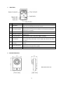
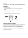
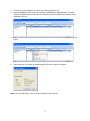
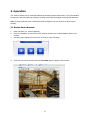
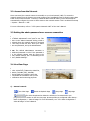
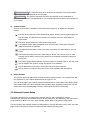
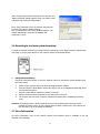
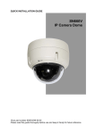
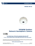
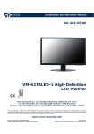
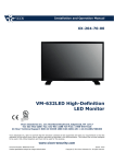
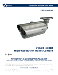
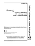
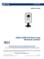
Quick Guide XX264-20-00 V905-CUBE HD Mini-Cube Network Camera Vicon Industries Inc., 89 Arkay Drive, Hauppauge, New York 11788 Tel: 631-952-2288 Fax: 631-951-2288 Toll Free: 800-645-9116 24-Hour Technical Support: 800-34-VICON (800-348-4266) UK: 44/(0) 1489-566300 Vicon Industries Inc. does not warrant that the functions contained in this equipment will meet your requirements or that the operation will be entirely error free or perform precisely as described in the documentation. This system has not been designed to be used in life-critical situations and must not be used for this purpose. www.vicon-security.com Document Number: 8009-8264-20-00 Product specifications subject to change without notice. Issued: 413 Copyright © 2013 Vicon Industries Inc. All rights reserved. 1. Description The information in this manual provides quick installation and setup procedures for the V905-CUBE cameras. These units should only be installed by a qualified technician using approved materials in conformance with federal, state, and local codes. Read these instructions thoroughly before beginning an installation. Always refer to Vicon’s website to assure you have the most up-to-date manual, www.vicon-security.com. The V905-CUBE HD Camera is designed for indoor security installation requiring small form factor cameras. This network camera provides 2 megapixel resolution and delivers crisp clear images that satisfy any installation need. It includes an integral 2.6 mm lens. A built in light LED provides superior image quality around the clock. The network camera provides triple-streaming video and supports H.264 compression for conserving bandwidth; MPEG-4 and M-JPEG compressions are also supported. Installation is made easy with Power over Ethernet (PoE); the camera also accepts 5 VDC. • Package Component The system comes with the following components: Cube Camera Installation CD Installation Guide Stand Adaptor Note: Check your package to make sure that you received the complete system, including all components shown above. • Front View 2 • Rear View NO 1 Name PIR Sensor Description The camera is equipped with a PIR sensor that has a maximum range of 16 ft (5 m) for detecting movement in the dark. The camera is equipped with a microphone and speaker. Two-way audio support allows for remote users to listen in on an area and communicate 2 Microphone/Speaker 3 Light 4 Network Connector 5 Power Connector For connection of the 5 VDC power adapter (included). 6 Reset Button Used for Factory Defaults. Press and hold the Reset Button for at least two seconds using a thin object, such as a paper clip. Wait for the camera with visitors or intruders. The camera is equipped with a white LED that illuminates the scene. Ethernet, RJ-45 port compatible with 10/100Mbps having PoE functionality. Modular jack. to reboot. 7 Network LED (Orange) 8 Power LED (Green) 9 Status LED (Red) Steady for connection to a 100Mbit/s network. Flashes for network activity. Steady green for normal operation or booting. Flashes green during firmware upgrade. Steady red for failed upgrade or booting. Camera Dimension Dimensions Unit: mm 3 2. Installation The network camera is ready for desk-top installation with the stand provided. The stand screws into the hole provided on the back of the camera. 2.1 Connection • • Connecting to the RJ-45 Connect a standard RJ-45 cable to the network port of the network camera. Generally a cross-over cable is used for direct connection to PC, while a direct cable is used for connection to a hub. A router featuring PoE (Power over Ethernet) can also be used to supply power to the camera. Micro SD memory slot Insert the SD memory card (customer supplied). Connecting the Power Connect the supplied 5 VDC power adaptor to the camera if not using PoE. 2.2 Network Connection and IP assignment The network camera is designed for use on an Ethernet network and requires an IP address for access. Most networks today have a DHCP server that automatically assigns IP addresses to connected devices. By factory default, your camera is set to obtain the IP address automatically via DHCP server. If your network does not have a DHCP server the network camera will use 192.168.1.100 as the default IP address. If DHCP is enabled and the product cannot be accessed, run the “Smart Manager” utility on the CD to search and allocate an IP address to your product or reset the product to the factory default settings and then perform the installation again. 4 1. 2. Connect the network camera / device to the network and power up. Start SmartManager utility (Start>All programs>SmartManager>SmartManager); the main window will display. After a short while any network devices connected to the network will be displayed in the list. 3. Select the camera on the list and click right button of the mouse. The pop-up menu displays as below. 4. Select Assign IP. The Assign IP window displays. Enter the required IP address. Note: For more information, refer to the Smart Manger User’s Manual. 5 3. Operation The network camera can be used with Windows® operating system and browsers. The recommended browsers are Internet Explorer®, Safari®, Firefox®, Opera® and Google® Chrome® with Windows. Note: To view streaming video in Microsoft® Internet Explorer, set your browser to allow ActiveX controls. 3.1 Access from a browser 1. 2. 3. Start a browser (i.e., Internet Explorer). Enter the IP address or host name of the network camera in the Location/Address field of your browser. A starting page displays. Click Live View or Setup to enter web page. 4. Click Live View for the network camera’s Live View page to appear in the browser. 6 3.2. Access from the Internet Once connected, the network camera is accessible on your local network (LAN). To access the network camera from the Internet you must configure your broadband router to allow incoming data traffic to the network camera. To do this, enable the NAT-traversal feature, which will attempt to automatically configure the router to allow access to the network camera. This is enabled from Setup > System > Network > NAT. For more information, refer to “3.5.5 System>Network>NAT” of the User’s Manual. 3.3 Setting the admin password over a secure connection To gain access to the product, the password for the default administrator user must be set. This is done in the “Admin Password” dialog, which is displayed when the network camera is accessed for the setup at the first time. Enter your admin name and password, set by the administrator. Note: The default administrator username is ADMIN and password is 1234. If the password is lost, the network camera must be reset to the factory default settings. See “3.6 Resetting to the Factory Default Settings”. 3.4 Live View Page The Live View page provides several screen modes: 1600x1200, 1280x1024, 1280x720, 800x600, 704x480 (576), 640x480, 352x240 (288) and 320x240. Select the most suitable in accordance with your PC specifications and monitoring purposes. 1) General controls Live View Page Search & Playback Page Setup Page Help Page The video drop-down list allows the selection of a customized or preprogrammed video stream on the live view page. Stream profiles are configured under Setup > Basic Configuration > Video & Image. For more information, see “3.5.1 Basic Configuration > Video & Image” of User’s Manual. 7 The resolution drop-down list allows the selection of the most suitable video resolution to be displayed on live view page. The protocol drop-down list allows the selection of the combination of protocols and methods to use depending on your viewing requirements and on the properties of your network. 2) Control toolbar The live viewer toolbar is available in the web browser page only. It displays the following buttons: The Stop button stops the video stream being played. Pressing the key again toggles the start and stop. The Start button connects to the network camera or start playing a video stream. The Pause button pauses the video stream being played. The Snapshot button takes a snapshot of the current image. The location where the image is saved can be specified. The Digital Zoom activates a zoom-in or zoom-out function for video image on the live screen. The Full Screen button causes the video image to fill the entire screen area. No other windows will be visible. Press the 'Esc' button on the computer keyboard to cancel full screen view. The Manual Trigger button activates a pop-up window to manually start or stop the event. Use the Speaker icon scale to control the volume of the speakers. Use the Microphone icon scale to control the volume of the microphone. Use the slider icon scale to control the volume of the speakers and microphones. 3) Video Streams The network camera provides several image and video stream formats. Your requirements and the properties of your network will determine the type you use. The Live View page in the network camera provides access to H.264, MPEG-4 and Motion JPEG video streams and to the list of available video streams. Other applications and clients can also access these video streams/images directly, without going via the Live View page. 3.5 Network Camera Setup This section describes how to configure the network camera, and is intended for product Administrators, who have unrestricted access to all the Setup tools, and Operators, who have access to the settings for Basic, Live View, Video & Image, Audio, Event, and System Configuration. You can configure the network camera by clicking Setup in the top right-hand corner of the Live View page. Click on this page to access the online help that explains the setup tools. 8 When accessing the network camera for the first time, the “Admin Password” dialog appears. Enter your admin name and password, set by the administrator. Note: If the password is lost, the network camera must be reset to the factory default settings. See “3.6 Resetting to the Factory Default Settings”. The default administrator username is “ADMIN” and password is “1234”. 3.6 Resetting to the factory default settings To reset the network camera to the original factory settings, go to the Setup>System> Maintenance web page or use the Reset button on the network camera, as described below: • Using the Reset Button Follow the instructions below to reset the network camera to the factory default settings using the Reset button. 1. 2. 3. 4. 5. Switch off the network camera by disconnecting the power adapter. Press and hold the Reset Button with a thin object, such as a straightened paperclip, while reconnecting the power. Keep the Reset Button pressed for at least 2 seconds. Release the Reset Button and wait for the Status LED to turn off. The network camera resets to factory defaults and restarts after completing the factory reset. Caution: Performing a Factory Reset results in the loss of any settings that have been saved. (Default IP is DHCP server. If your network does not have a DHCP server, the network will use 192.168.1.100 as the default IP address.) 3.7 More Information For more information, refer to the network camera User’s Manual, which is available on the CD included in this package. 9 10 11 Vicon Industries Inc. Corporate Headquarters 89 Arkay Drive Hauppauge, New York 11788 631-952-2288 800-645-9116 Fax: 631-951-2288 Vicon Europe Headquarters Brunel Way Fareham, PO15 5TX United Kingdom +44 (0) 1489 566300 Fax: +44 (0) 1489 566322 Vicon Germany Kornstieg 3 D-24537 Neumuenster Phone: +49 (0) 4321 8790 Fax: +49 (0) 4321 879 97 Far East Office Unit 5, 17/F, Metropole Square 2 On Yiu Street, Shatin New Territories, Hong Kong (852) 2145-7118 Fax: (852) 2145-7117 Internet Address: www.vicon-security.com 50303452A