1
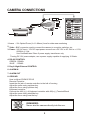
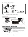
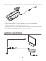
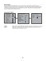
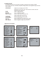
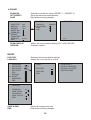
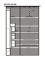
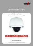
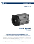
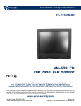
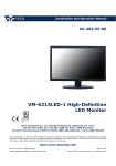
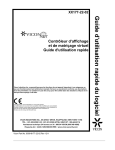
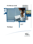
Installation and Operation Guide
XX234-00-02
V660B-488IR
High-Resolution Bullet Camera
Vicon Industries Inc., 89 Arkay Drive, Hauppauge, New York 11788
Tel: 631-952-2288 Fax: 631-951-2288 Toll Free: 800-645-9116
24-Hour Technical Support: 800-34-VICON (800-348-4266) UK: 44/(0) 1489-566300
Vicon Industries Inc. does not warrant that the functions contained in this equipment will meet your requirements or that the
operation will be entirely error free or perform precisely as described in the documentation. This system has not been designed
to be used in life-critical situations and must not be used for this purpose.
www.vicon-security.com
Document Number: 8009-8234-00-02
Product specifications subject to change without notice.
Issued: 0512
Copyright © 2012 Vicon Industries Inc. All rights reserved.
WARNING
TO REDUCE THE RISK OF FIRE OR ELECTRIC SHOCK, DO NOT EXPOSE THIS PRODUCT TO RAIN OR
MOISTURE. DO NOT INSERT ANY METALLIC OBJECTS THROUGH THE VENTILATION GRILLS OR
OTHER OPENINGS ON THE EQUIPMENT.
CAUTION
CAUTION
CAUTION: TO REDUCE THE RISK OF ELECTRIC SHOCK,
DO NOT REMOVE COVER(OR BACK).
NO USER-SERVICEABLE PARTS INSIDE.
REFER SERVICING TO QUALIFIED SERVICE PERSONNEL.
EXPLANATION OF GRAPHICAL SYMBOLS
The lightning flash with arrowhead symbol, within an equilateral triangle, is
intended to alert the user to the presence of uninsulated "dangerous voltage"
within the product's enclosure that may be of sufficient magnitude to constitute a
risk of electric shock to persons.
The exclamation point within an equilateral triangle is intended to alert the user to
the presence of important operating and maintenance (servicing) instructions in the
literature accompanying the product.
PRECAUTIONS
Safety -----------------------------------------
Cleaning --------------------------------------
Should any liquid or solid object fall into the cabinet,
unplug the unit and have it checked by the qualified
personnel before operating it any further.
Clean the unit with a slightly damp soft cloth.
Use a mild household detergent. Never use
strong solvents such as thinner or benzine as
they might damage the finish of the unit.
Unplug the unit from the wall oulet if it is not going to
be used for several days or more. To disconnect the
cord, pull it out by the plug. Never pull the cord itself.
Retain the original carton and packing
materials for safe transport of this unit in the
future.
Allow adequate air circulation to prevent internal heat
build-up. Do not place the unit on surfaces (rugs,
blankets, etc.) or near materials(curtains, draperies)
that may block the ventilation holes.
Height and vertical linearity controls located at the
rear panel are for special adjustments by qualified
personnel only.
ii
FCC COMPLIANCE STATEMENT
FCC INFORMATION : THIS EQUIPMENT HAS BEEN TESTED
AND FOUND TO COMPLY WITH THE LIMITS FOR A CLASS A DIGITAL
DEVICE, PURSUANT TO PART 15 OF THE FCC RULES. THESE
LIMITS ARE DESIGNED TO PROVIDE REASONABLE PROTECTION
AGAINST HARMFUL INTERFERENCE WHEN THE EQUIPMENT IS
OPERATED IN A COMMERCIAL ENVIRONMENT. THIS EQUIPMENT
GENERATES, USES, AND CAN RADIATE RADIO FREQUENCY
ENERGY AND IF NOT INSTALLED AND USED IN ACCORDANCE WITH
THE INSTRUCTION MANUAL, MAY CAUSE HARMFUL INTERFERENCE
TO RADIO COMMUNICATIONS. OPERATION OF THIS EQUIPMENT IN
A RESIDENTIAL AREA IS LIKELY TO CAUSE HARMFUL
INTERFERENCE IN WHICH CASE THE USER WILL BE REQUIRED TO
CORRECT THE INTERFERENCE AT HIS OWN EXPENSE.
CAUTION : CHANGES OR MODIFICATIONS NOT EXPRESSLY
APPROVED BY THE PARTY RESPONSIBLE FOR COMPLIANCE
COULD VOID THE USER'S AUTHORITY TO OPERATE THE EQUIPMENT.
THIS CLASS A DIGITAL APPARATUS COMPLIES WITH CANADIAN
ICES-003.
NORME NMB-003 DU CANADA.
CE COMPLIANCE STATEMENT
WARNING
This is a Class A product. In a domestic environment this product
may cause radio interference in which case the user may be required
to take adequate measures.
iii
IMPORTANT SAFETY INSTRUCTIONS
1. Read these instructions.
2. Keep these instructions.
3. Heed all warnings.
4 . Follow all instructions.
5. Do not use this apparatus near water.
6. Clean only with dry cloth.
7. Do not block any ventilation openings. Install in accordance with the
manufacturer's instructions.
8. Do not install near any heat sources such as radiators, heat registers,
stoves, or other apparatus (including amplifiers) that produce heat.
9. Do not defeat the safety purpose of the polarized or grounding-type
plug. A polarized plug has two blades with one wider than the other.
A grounding type plug has two blades and a third grounding prong.
The wide blade or the third prong are provided for your safety. If the
provided plug does not fit into your outlet, consult an electrician for
replacement of the obsolete outlet.
10.Protect the power cord from being walked on or pinched particularly
at plugs, convenience receptacles, and the point where they exit from
the apparatus.
11. Only use attachments/accessories specified by the manufacturer.
12. Use only with the cart, stand, tripod, bracket,
or table specified by the manufacturer,
or sold with the apparatus.
When a cart is used,use caution when moving
the cart/apparatus combination to avoid injury
from tip-over.
13. Unplug this apparatus during lightning storms or when unused for
long periods of time.
14. Refer all servicing to qualified service personnel. Servicing is
required when the apparatus has been damaged in any way, such as
power-supply cord or plug is damaged, liquid has been moisture, does
not operate normally, or has been dropped.
15. CAUTION THESE SERVICING INSTRUCTIONS ARE FOR USE BY
QUALIFIED SERVICE PERSONNEL ONLY. TO REDUCE THE RISK
OF ELECTRIC SHOCK DO NOT PERFORM ANY SERVICING OTHER
THAN THAT CONTAINED IN THE OPERATING INSTRUCTIONS
UNLESS YOU QRE QUALIFIED TO DO SO.
16. Use satisfy clause 2.5 of IEC60950-1/UL60950-1 or Certified/Listed
Class 2 power source only.
iv
INTRODUCTION
The camera provides high-quality images using Sony CCD technology especially
designed for closed-circuit television (CCTV) and security surveillance applications.
Features:
High resolution and high performance 1/3" Sony Super HAD TM
Technology
Excellent picture quality
600 lines(Color) of resolution
22x Optical Zoom( f=4.1~88mm) Lens F1.6~3.7
Zoom and Focus Control via Remote or Keyboard Controller
0.1 lux(Color), 0 lux(B/W) with LEDs on @ F1.2, 30IRE Sensitivity
Auto electronic shutter [1/60(1/50) ~ 1/100,000] and manual electronic shutter modes
OSD (On Screen Display)
Auto and manual white balance modes
DWDR (Digital Wide Dynamic Range)
OSD Font Color ( 16 Color)
BLC (Back Light Compensation)
Day&Night (Auto / DAY / NIGHT / EXT)
Private Mask (8 position, 16 Colors)
AGC (Auto Gain Control)
MIRROR (ON/OFF)
Motion Detection(4 point)
Zoom Preset 1~5
HLC (High Light Compensation)
DPC (Dead Pixel Cancellation)
IR Range distance up to 60M
RS-485 Control (Compatible with Pelco D and Pelco P protocols)
ALARM External IN / ALARM (Motion) External OUT
Day & Night External Control
Operates in AC24V ± 10% / DC12V ± 10%
Weatherproof housing IP66
Use Certified / Listed Class 2 power source only
Camera Mount : camera mounts directly to the wall or ceiling
IMPORTANT : The user of this camera is responsible for checking
and complying with local, state, and federal laws and statutes concerning
the recording and monitoring of audio signals.
1
CAMERA CONNECTIONS
2
4
5
6
7
8
AC/DC+
AC/DC-
GND
1
ALARM -OUT
3
D/N EXT -IN
ALARM-IN
1. Lens : 22x Optical Zoom( f=4.1~88mm) Lens for wide area monitoring
2 . Video : BNC connector used to connect the camera to a monitor, switcher, etc.
3. Power : 24V AC input / 12V DC input power source from a DC 12V or AC 24V ac +/-10%
60/50Hz +/-1Hz.
Use Certified/Listed Class 2 power supply transformer only.
*If using DC 12V power adaptor, use a power supply capable of supplying 10 Watts.
4. RS 485 CONTROL
GREEN : RS485+
BLUE : RS485 5. Day & Night External CONTROL
6. ALARM IN
7. ALARM OUT
8. GROUND
How to Adjust ZOOM /FOCUS
Remote Controller
Insert the din jack of remote controller to the hall of housing
Adjust the zoom using up/down key
Adjust the focus using up/down key
Keyboard controller
Connect the 485(+)(-) of Keyboard controller with 485(+)(-) Terminal Block
Adjust the zoom using tele/wide key
Adjust the focus using near/far key
REMINDER:
Never aim the camera directly into the sun.
2
PACKAGE CONTENTS
SUNSHIELD
CAMERA
SUNSHIELD-BOLT
Screw
SCREWS
REMOTE CONTROLLER
Firmly attach the bracket to the wall or ceiling
DIMENSIONS
(3.4)
(6.5)
(10.9)
UNIT : mm (inches)
WATER INGRESS PREVENTION
After using the Remote Control cable,
disconnect it and insert the Remote Control Port Cap.
Secure it tightly.
Caution : This is a sealed camera with no internal
adjustments and as such opening the case may
invalidate the warranty.
REMOTE CONTROL PORT CAP
3
CAMERA FIXING
Use the 3 location holes around the base of
the bracket to secure the camera to a wall or
ceiling using fixing suitable to the type of surface
CAMERA ADJUSTMENT
The camera is supplied with a remote control set up tool. To connect the remote control
to the camera, first remove the Remote control port cap at the rear of the camera:
REMOTE CONTROL PORT CAP
4
Connect the remote control using the 6 pin din connector end to the socket within the camera:
Connect the BNC to a set up monitor to view the picture and On Screen Menus.
To Enter the menus press the button on the remote control.
To Navigate the menus, move the button left/Right/Up and Down, press the button to Enter.
END - takes you back a step in the OSD or exits from the OSD
CAMERA CONNECTION
5
THE DEFINITION OF TERMS
White Balance
Compensates for deviations in the white color caused by changes in the color
temperature of the light source so that the colors are reproduced correctly.
Exposure
Adjusts the images to the optimum brightness.
SHUTTER (Electronic Shutter)
Controls the integration time (exposure) of the photodiode array and reduces blooming,
overexposure, and smear when capturing moving objects.
Flicker (FLC)
Avoids image flicker when there is a discrepancy between current and frequency
AGC (Automatic Gain Control)
Automatically adjusts (boosts) the video signal to the required level to produce a quality
image in low light situations
Back Light Compensation (BLC)
Compensates for the brightness of the subjects with a large amount of background light
that would make it practically impossible to see any details of the subjects. Adjusts the
iris so that a distinctive subject and the background are delivered at the same time.
HLC (High Light Compensation)
When a high-brightness subject is shot, it may not be brought into focus because of the
large surface area over which the high-brightness pixels are spread.
In cases like this, the high-brightness subject can be brought into focus by using this
function.
LENS SHAD. (Lens Shading)
This function is the make brighter image of corner of screen.
Mask
Hides one or more areas that the user does not want to be displayed on screen.
Masks can be set with their own display area, color, darkness and mosaic processing.
Detection
Detects motion within the scene using one of the available methods.
Some methods trigger the Alarm output.
Sharpness
Reducing this parameter adjusts the noise level to smooth out the "noise" caused by
the compression.
Caution should be taken not to reduce it too much, which may result in a blurred image.
6
Resolution
Controls the display of fine details. The higher the resolution, the higher level of
details can be seen.
2D-NR (Digital Noise Reduction)
Adjusts the illuminance noise level in low light situations by reducing image noise in
order to improve the image.
Nega
Reverses the color signals for the Chroma signal so the image looks like a “negative.”
DPC(Dead Pixel Cancellation)
white pixels whose frequency of occurrence varies in proportion to the temperature
are sometimes observed when the devices are used under the influence of external
factors or especially high temperatures. The white pixel detection and compensation
function can automatically detect and compensate up to 64 white pixels with the highest
detection level in sequence so as to maintain the image quality.
MIRROR
Reverses the image on the screen left to right or right to left
(as it would be seen in a mirror.)
DWDR
When the camera looks at a dark area, there may be loss of dark detail in the
low-brightness subjects.
Using DWDR (on) may produce a higher quality image.
FONT COLOR
Adjust OSD menu color from a choice of 16 different colors.
7
STRUCTURE OF THE SETUP MENU
<SETUP>
EXPOSURE
WHITE BAL
BACKLIGHT
DAY NIGHT
DPC
SPECIAL
RESET
SAVE&END
END
<EXPOSURE>
SHUTTER
BRIGHTNESS
AGC
DWDR
IRIS ADJ
END
<WHITE BAL>
<BACKLIGHT>
<DAY NIGHT>
ATW1
ATW2
AWC -> SET
MANUAL
OFF
BLC
HLC
COLOR
AUTO
B/W
EXT
<DPC>
<SPECIAL>
<RESET>
COVER THE LENS
ENTER KEY FOR START
OTHERS FOR END
CAM TITLE
MOTION
PRIVACY
IMAGE ADJ
COMM ADJ
PRESET
ZOOM DISP
VERSION
END
FACTORY
LENS ADJ
END
8
EXPOSURE
The EXPOSURE menu is used to set the automatic light control method for the camera.
It provides the ability to adjust the shutter speed, brightness, AGC, dynamic range and
iris functions of the camera.
1) SHUTTER
2) BRIGHTNESS
3) AGC
4) DWDR
5) IRIS ADJ
Select the shutter mode.(Auto,1/60(50), FLK~ 1/100,000 sec)
Can be changed while in shutter mode.
Adjust BRIGHTNESS level (0 ~ 255)
Can be adjusted while in DC/ manual lens mode.
Auto gain control (OFF / LOW / MIDDLE / HIGH)
Digital Wide dynamic range(Xtended Dynamic Range)
OFF / ON
Select the IRIS Open.(F1.6~F32)
► EXPOSURE
WHITE BAL
BACKLIGHT
DAY NIGHT
DPC
SPECIAL
RESET
SAVE&END
END
ATW2
AUTO
EXPOSURE
SHUTTER
BRIGHTNESS
AGC
D-WDR
IRIS ADJ
END
AUTO
50
---OFF
F1.6
WHITE BAL
The screen color can be adjusted by using the WHITE BALANCE function.
It compensates for deviations in the white color caused by changes in the color temperature
of the light source so that the colors are reproduced correctly.
1) ATW1
2) ATW2
3) AWC -> SET
4) MANUAL
Set the color temperature 2500oK 10000oK
Range is narrower than ATW2 but compensates better than ATW2.
o
o
Set the color temperature 2000 K 13000 K
Range is wider than ATW1 but does not compensate as well as ATW1.
Press the ENTER button while the camera is directed at a piece of
white paper to obtain the optimum state under current illumination.
If the environment or light source changes you will have to reset the
white balance.
Manual mode. User can change R and B gain manually.
<WHITE BAL MANUAL MODE>
EXPOSURE
► WHITE BAL
BACKLIGHT
DAY NIGHT
DPC
SPECIAL
RESET
SAVE&END
END
ATW2
AUTO
WHITE BAL MANUAL
► COLOR TEMP OUTDOOR
BLUE
-----------RED
-----------END
9
BACKLIGHT
The BLC (Backlight Compensation) function provides compensation by increasing the
brightness of the overall screen to compensate for the overly bright areas of the background
so that the darker areas are reproduced with more clarity. This provides a balanced scene
where all objects are properly exposed.
<BACKLIGHT MODE>
EXPOSURE
WHITE BAL
► BACKLIGHT
DAY NIGHT
DPC
SPECIAL
RESET
SAVE&END
END
BACKLIGHT BLC
BACKLIGHT HLC
ATW2
AUTO
AREA SEL
AREA STARE
GAIN
HEIGHT
WIDTH
LEFT/RIGHT
TOP/BOTTOM
END
AREA1
ON
042
07
08
03
04
LEVEL
MODE
END
200
NIGHT ONLY
1) BLC
Back Light Compensation prevents back lighting from affecting the scene.
2) HLC
High Light Compensation filters brightly lit areas to provide more even
exposure across all areas of scene.
10
DAY NIGHT
The DAY/NIGHT menu is used to configure the day and night related setting for the camera.
The camera can turn the IR(infrared)filter on or off.
Mode : COLOR / AUTO / B/W / EXT
<DAY NIGHT AUTO MODE>
EXPOSURE
WHITE BAL
BACKLIGHT
► DAY NIGHT
DPC
SPECIAL
RESET
SAVE&END
END
1)SENSE SEL
SENSOR
AGC
ATW2
AUTO
DAY NIGHT AUTO
► SENSE SEL. SENSOR
D -N LEVEL 237
D-N DELAY
5
SEC
N-D LEVEL
193
N-D DELAY
5
SEC
END
Select the day and night sensing mode. (SENSOR/AGC)
Day and night changes are made according to the sensor inputs.
Day and night changes are made according to the brightness of the
image. Use only when the camera is installed in a dark place but the
camera is viewing a bright place. When used in a normal installation
hunting may occur.
<DAY NIGHT B/W MODE>
EXPOSURE
WHITE BAL
BACKLIGHT
► DAY NIGHT
DPC
SPECIAL
RESET
SAVE&END
END
ATW2
AUTO
DAY NIGHT B/W
BURST
► IR SMART
END
IR SMART
OFF
ON
► IR GAIN
HEIGHT
WIDTH
LEFT/RIGHT
TOP/BOTTOM
END
050
13
13
01
01
DPC
DPC Auto setting (Automatically finds and cancels dead pixels.)
EXPOSURE
WHITE BAL
BACKLIGHT
DAY NIGHT
DPC
► SPECIAL
RESET
SAVE&END
END
DPC
ATW2
AUTO
COVER THE LENS
ENTER KEY FOR START
► OTHERS FOR END
11
PROCESSING NOW...
SPECIAL
The SPECIAL menu provides the ability to set up the camera title, motion detection,
privacy mask, image adjust, communication adjust, zoom preset and zoom position display
functions of the camera.
1) CAM TITLE
Maximum of 15 characters are allowed.
A. Character Table
B. Command Line
C. CAM TITLE
A
.
B
←→ CLR POS END
C
CAM TITLE
← : Move to left
→ : Move to right
CLR : Erase all characters
POS : Move the position of title display
END : End
2) MOTION
MD stands for motion detection. Maximum of 4 areas are allowed.
AREA SELECT
AREA STATE
HEIGHT
WIDTH
LEFT/RIGHT
TOP/BOTTOM
DEGREE
VIEW
ALARM
EXPOSURE
WHITE BAL
BACKLIGHT
DAY NIGHT
DPC
► SPECIAL
RESET
SAVE&END
END
Select MD area number. (AREA1 ~AREA4)
Select MD ON/OFF
Adjust height of MD area
Adjust width of MD area
Adjust the location of the MD area with boundary LEFT and RIGHT.
Adjust the location of the MD area with boundary TOP and BOTTOM
Adjust sensitivity of MD area.(0~255)
The screen displays with pink dots. When a motion is detected
in the selected area, the pink dots are displayed on the screen.
Select preset move when MD occurred. (OFF/ PRESET 1 ~ PRESET 5)
Select preset move dwell time. (03 SEC ~ 60 SEC)
SPECIAL
ATW2
AUTO
MOTION
CAM TITLE
► MOTION
PRIVACY
IMAGE ADJ
COMM ADJ
PRESET
ZOOM DISP
VERSION
END
ALARM AREA1
PRESET
► DWELL TIME
END
OFF
03 SEC
12
OFF
OFF
OFF
ON
01.00
► AREA SELECT
AREA STATE
HEIGHT
WIDTH
LEFT/RIGHT
TOP/BOTTOM
DEGREE
VIEW
ALARM
END
AREA1
ON
04
04
02
02
038
OFF
3) PRIVACY
It used to hide one or more areas which the user does not want to be displayed on screen.
Privacy Masks can be set with their own display area and color. Maximum of 8 areas are
allowed.
AREA SELECT
AREA STATE
HEIGHT
WIDTH
LEFT/RIGHT
TOP/BOTTOM
Select MASK area number.(Area 1 ~ Area 8)
Select MASK ON/OFF
Adjust height of MASK area
Adjust width of MASK area
Adjust the location of the MASK area with boundary LEFT and RIGHT
Adjust the location of the MASK area with boundary
TOP and BOTTOM.
Select MASK color. (0~15)
COLOR
<PRIVACY MODE>
EXPOSURE
WHITE BAL
BACKLIGHT
DAY NIGHT
DPC
► SPECIAL
RESET
SAVE&END
END
SPECIAL
ATW2
AUTO
CAM TITLE
MOTION
► PRIVACY
IMAGE ADJ
COMM ADJ
PRESET
ZOOM DISP
VERSION
END
13
OFF
OFF
OFF
ON
01.00
PRIVACY
► AREA SELECT
AREA STATE
HEIGHT
WIDTH
LEFT/RIGHT
TOP/BOTTOM
COLOR
END
AREA1
ON
032
032
020
016
00
4) IMAGE ADJUST
The IMAGE ADJUST menu provides the ability to adjust the lens shading, 2DNR,
mirror image, font color, contrast, sharpness, display device and negative image functions
of the camera.
LENS SHAD
2DNR
MIRROR
FONT COLOR
CONTRAST
SHARPNESS
DISPLAY
NEG. IMAGE
Adjust Lens shading level (0~255)
Depending on the level value, dims down the center area and
brightens up the side area.
Select 2DNR ON/OFF
Select MIRROR ON/OFF
Select FONT COLOR level (0~15)
Select IDR TITLE level (0~15)
Adjust CONTRAST level (0~255)
Adjust SHARPNESS level (0~31)
Select DISPLAY mode (CRT /LCD/USER)
Select Negative image mode ON /OFF
<IMAGE ADJUST MODE>
SPECIAL
CAM TITLE
MOTION
PRIVACY
► IMAGE ADJ
COMM ADJ
PRESET
ZOOM DISP
VERSION
END
SPECIAL
CAM TITLE
MOTION
PRIVACY
IMAGE ADJ
►
COMM ADJ
PRESET
ZOOM DISP
VERSION
END
IMAGE ADJUST
OFF
OFF
OFF
ON
01.00
► LENS SHAD
2DNR
MIRROR
FONT COLOR
CONTRAST
SHARPNESS
DISPLAY
NEG.IMAGE
END
ON
ON
OFF
ON
01.00
►
LENS SHAD
2DNR
MIRROR
FONT COLOR
CONTRAST
SHARPNESS
DISPLAY
NEG.IMAGE
END
14
006
122
21
CRT
OFF
IMAGE ADJUST
OFF
OFF
OFF
LENS SHAD
► LEVEL
END
ON
ON
OFF
122
21
CRT
OFF
FONT COLOR
► FONT
03
ID&TITLE
03
END
SPECIAL
CAM TITLE
MOTION
PRIVACY
► IMAGE ADJ
COMM ADJ
PRESET
ZOOM DISP
VERSION
END
IMAGE ADJUST
OFF
OFF
OFF
ON
01.00
► LENS SHAD
2DNR
MIRROR
FONT COLOR
CONTRAST
SHARPNESS
DISPLAY
NEG.IMAGE
END
ON
ON
OFF
CRT ADJUST
► PED LEVEL
COLOR GAIN
END
28
192
LCD AJUST
► GAMMA
PED LEVEL
COLOR GAIN
END
0.65
28
176
USER AJUST
► GAMMA
PED LEVEL
COLOR GAIN
END
0.50
28
176
122
21
CRT
OFF
5) COMM (RS485) ADJUST
The camera can be controlled remotely by a control keypad using a RS485 connection.
CAM ID
BAUD RATE
PROTOCOL
DISPLAY ID
ID POS
Select the camera ID.(001 ~255)
Select serial communication speed (2400 / 4800 / 9600 / 19200)
Select RS485 protocol (FASTRAX / PELCO-P / PELCO-D)
Select camera ID display ON /OFF.
Select camera ID display position.
SPECIAL
CAM TITLE
MOTION
PRIVACY
IMAGE ADJ
► COMM ADJ
PRESET
ZOOM DISP
VERSION
END
COMM ADJ
OFF
OFF
OFF
ON
► CAM ID
BAUD RATE
PROTOCOL
DISPLAY ID
ID POS
SAVE COMM
END
01.00
15
255
9600
FASTRAX
OFF
6) PRESET
ZOOM SEL
SET PRESET
SAVE
Select the number for setup.(PERSET 1 ~ PRESET 5)
Setup the selected preset position.
Exits without saving changes.
PRESET
SPECIAL
CAM TITLE
MOTION
PRIVACY
IMAGE ADJ
COMM ADJ
► PRESET
ZOOM DISP
VERSION
END
OFF
OFF
OFF
SET PRESET1
ZOOM SEL
► SET PRESET
SAVE
END
PRESET1
ON
01X
01.00
ZOOM DISPLAY
VERSION
Select the zoom position display (01X ~22X) ON /OFF.
Firmware version.
RESET
FACTORY
LENS ADJ
EXPOSURE
WHITE BAL
BACKLIGHT
DAY NIGHT
DPC
SPECIAL
► RESET
SAVE&END
END
Restores the factory default settings.
Adjust the zoom and focus of lens.
RESET
ATW2
AUTO
FACTORY
LENS ADJ
END
LENS ADJ
ZOOM ADJ
SAVE ZOOM
FOCUS ADJ
SAVE FOCUS
END
SAVE & END
END
04
07
Saves all changes and exits.
Exits without saving changes.
16
DO NOT ADJUST
WITHOUT COLLIMATOR
ENTER KEY FOR START
OTHERS FOR END
SPECIFICATIONS
MODEL
Power
General
NTSC
PAL
Power source
AC24V ± 10% / DC12V ± 10%
Power consumption
10.0W(700mA)
1/4" Sony Super HAD
Image sensor
Total pixels
795(H) x 596(V)
811(H) x 508(V)
Scanning system
2:1 interlace
Scanning frequency
15.734KHz(H) x 59.94Hz(V)
15.625KHz(H) x 50Hz(V)
Sync. system
Internal
Electronic Shutter
1/60 ~ 1/100,000 sec
1/50 ~ 1/100,000 sec
Resolution
600TV lines (Color)
0.1 Lux(Color), 0 Lux (IR LED ON)
Min. illumination
1.0 Vp-p (75 ohm, composite)
Video output
S/N ratio
More than 50dB (AGC OFF)
IR LED 78EA, Sensor 1EA
IR LED/SENSOR
LED Lighting Distance
60M
External remote control (ADKEY), RS485
Camera Control
Zoom Ratio
Optical x22
Lens
Focal Length
F = 4.1~ 88mm
F1.6(Wide) ~ F3.7(Tele)
Aperture
AUTO, / FIX (1/60~ 1/100,000sec) AUTO, / FIX (1/50~ 1/100,000sec)
SHUTTER
LEVEL 0~255
BRIGHTNESS
EXPOSURE AGC
OFF / LOW / MIDDLE / HIGH
ON / OFF
DWDR
Lens lris
F1.6 ~32
ATW1, ATW2, AWC -> SET, MANUAL(INDOOR,OUTDOOR,USER)
White
Balance
F
LEVEL 0~255
HLC
U BACKLIGHT BLC
AREA SEL, AREA STATE, GAIN, AREA SIZE
N
SENSOR /AGC, D/N LEVEL, DELAY
AUTO
COLOR ONLY
COLOR
C
DAY&NIGHT
BURST, IR SMART, IR LEVEL
B/W
T
Externak D/N Control
EXIT
I DPC
64ponit DEAD PIXEL CORRECTION
O
ON / OFF
CAMTITLE
MOTION
AREA1~4, AREA STATE, DEGREE, VIEW, ALRAN
N
PRIVCY
AREA1~8
SPECIAL
LENS SHAD/ 2DNR/ MIRROR/ FONT COLOR/
IMAGE ADJ
CONTRAST SHAPRNESS/ DLSPLAY/ NEG.IMAGE
COMM ADJ
Language
CAM ID / BAUD RATE / PROTOCOL / DISPLAYID / ID POS
English
Preset 1 ~ 5
3-Pin Terminal Block
BNC Connector
14oF ~ 122oF (-10oC ~ +50o C)
IP66
Die-Casting Aluminum
0 ~ 96% (non-condensing)
1.3kg
Preset
Power input
Video output
Connector Operating temperature
IP Rating
&
Materials
etc.
Operating humidity
Weight
17
Vicon Standard Equipment Warranty
Vicon Industries Inc. (the “Company”) warrants your equipment to be free from defects in material and
workmanship under Normal Use from the date of original retail purchase for a period of three years, with the
following exceptions:
1.
VCRs, all models: Labor and video heads warranted for 120 days from date of original retail
purchase. All other parts warranted for one year from date of original retail purchase.
2. LCD and CRT monitors, all models: One year from date of original retail purchase.
3. Uninterruptible Power Supplies: Two years from date of original retail purchase.
4. VDR-700 Recorder Series: One year from date of original retail purchase.
5. V5616MUX: One year from date of original retail purchase.
6. Arecont Cameras: One year from date of original retail purchase.
7. FMC series fiber-optic media converters and associated accessories: Lifetime warranty.
8. For PTZ cameras, “Normal Use” excludes prolonged use of lens and pan-and-tilt motors, gear
heads, and gears due to continuous use of “autopan” or “tour” modes of operation. Such
continuous operation is outside the scope of this warranty.
9. Vicon Security Management Systems (SMS) All Models: All hardware is warranted for two years
from date of original retail purchase.
10. Any product sold as “special” or not listed in Vicon’s commercial price list: One year from date of
original retail purchase.
Date of retail purchase is the date original end-user takes possession of the equipment, or, at the sole
discretion of the Company, the date the equipment first becomes operational by the original end-user.
The sole remedy under this Warranty is that defective equipment be repaired or (at the Company’s option)
replaced, at Company repair centers, provided the equipment has been authorized for return by the
Company, and the return shipment is prepaid in accordance with policy.
The Company will not be obligated to repair or replace equipment showing abuse or damage, or to parts
which in the judgment of the Company are not defective, or any equipment which may have been tampered
with, altered, misused, or been subject to unauthorized repair.
Software supplied either separately or in hardware is furnished on an “As Is” basis. Vicon does not
warrant that such software shall be error (bug) free. Software support via telephone, if provided at
no cost, may be discontinued at any time without notice at Vicon’s sole discretion. Vicon reserves
the right to make changes to its software in any of its products at any time and without notice.
This Warranty is in lieu of all other conditions and warranties express or implied as to the Goods,
including any warranty of merchantability or fitness and the remedy specified in this Warranty is in
lieu of all other remedies available to the Purchaser.
No one is authorized to assume any liability on behalf of the Company, or impose any obligations on it in
connection with the sale of any Goods, other than that which is specified above. In no event will the
Company be liable for indirect, special, incidental, consequential, or other damages, whether arising from
interrupted equipment operation, loss of data, replacement of equipment or software, costs or repairs
undertaken by the Purchaser, or other causes.
This warranty applies to all sales made by the Company or its dealers and shall be governed by the laws of
New York State without regard to its conflict of laws principles. This Warranty shall be enforceable against
the Company only in the courts located in the State of New York.
The form of this Warranty is effective March 1, 2011.
THE TERMS OF THIS WARRANTY APPLY ONLY TO SALES MADE WHILE THIS WARRANTY IS IN
EFFECT. THIS WARRANTY SHALL BE OF NO EFFECT IF AT THE TIME OF SALE A DIFFERENT
WARRANTY IS POSTED ON THE COMPANY’S WEBSITE, WWW.VICON-SECURITY.COM. IN THAT
EVENT, THE TERMS OF THE POSTED WARRANTY SHALL APPLY EXCLUSIVELY.
Vicon Part Number: 8006-9010-03-09 Rev 0311
Vicon Industries Inc.
Corporate Headquarters
89 Arkay Drive
Hauppauge, New York 11788
631-952-CCTV (2288) 800-645-9116
Fax: 631-951-CCTV (2288)
Vicon Europe
Headquarters
Brunel Way
Fareham, PO15 5TX
United Kingdom
+44 (0) 1489 566300
Fax: +44 (0) 1489 566322
Vicon Germany
Kornstieg 3
D-24537 Neumuenster
Phone: +49 (0) 4321 8790
Fax: +49 (0) 4321 879 97
Far East Office
Unit 5, 17/F, Metropole Square
2 On Yiu Street, Shatin
New Territories,
Hong Kong
(852) 2145-7118
Fax: (852) 2145-7117
Internet Address: www.vicon-security.com
50302996C