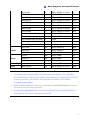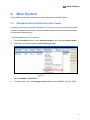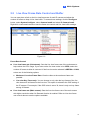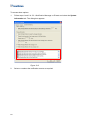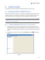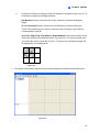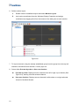
1
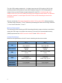
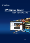
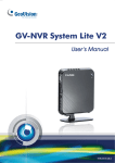
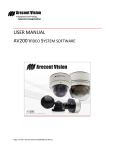
New Feature Guide V8.5 © 2011 GeoVision, Inc. All rights reserved. Under the copyright laws, this manual may not be copied, in whole or in part, without the written consent of GeoVision. Every effort has been made to ensure that the information in this manual is accurate. GeoVision, Inc. makes no expressed or implied warranty of any kind and assumes no responsibility for errors or omissions. No liability is assumed for incidental or consequential damages arising from the use of the information or products contained herein. Features and specifications are subject to change without notice. GeoVision, Inc. 9F, No. 246, Sec. 1, Neihu Rd., Neihu District, Taipei, Taiwan Tel: +886-2-8797-8377 Fax: +886-2-8797-8335 http://www.geovision.com.tw Trademarks used in this manual: GeoVision, the GeoVision logo and GV series products are trademarks of GeoVision, Inc. Windows and Windows XP are registered trademarks of Microsoft Corporation. July 2011 Feature Guide for V8.5 GeoVision Surveillance System Welcome to the Feature Guide for V8.5 GeoVision Surveillance System. This Guide provides an overview of key features in V8.5 GV-System. It also includes information about how the features differ from similar features in earlier versions. Cards Supported V8.5 only supports the following GV video capture cards: • • • • • • • • • • • • • • • • • GV-600(S) V3.20 and later GV-650(S) V3.30 and later GV-800(S) V3.30 and later GV-804A V3.10 and later GV-600A GV-650A GV-800A GV-900A GV-600B GV-650B GV-800B GV-1120, GV-1120A All Series GV-1240, GV-1240A All Series GV-1480, GV-1480A All Series GV-1008 GV-3008 GV-4008, GV-4008A Note that GV-600 (V4), GV-650 (V4) and GV-800 (V4) and GV-804 (V4) Cards are renamed to GV-600A, GV-650A, GV-800A and GV-804A. These V4 and A Cards are the same video capture cards i Contents Cards Supported.................................................. i Contents .............................................................. ii 1. New Supports and Specifications ................. 1 1.1 Enhanced H.264 and Support for GPU Decoding................................................1 1.2 Enhanced Multi-Channel Playback and Related Specifications ...........................5 1.3 Support for 16 kHz / 16 bit Audio Codec ..............................................................5 1.4 Support for New IP Devices .................................................................................6 1.5 Setting Configuration without Stopping Recording ...............................................8 1.6 Support for PTZ Functions through ONVIF ..........................................................8 2. Main System.................................................... 9 2.1 Standard and GeoVision Format Codec...............................................................9 2.2 Live View Frame Rate Control and Buffer .......................................................... 11 2.3 Automatic Daylight Saving Time Synchronization ..............................................12 2.4 Automatic Setup of IP Devices ...........................................................................13 2.5 Accessing Control Panel of GV-IP Devices ........................................................14 2.6 Wide Angle Lens Dewarping to Correct Distortion .............................................15 2.7 Display Ratio Adjustment in Fisheye Live View..................................................16 2.8 Object Tracking in Fisheye Live View.................................................................17 2.9 Enhanced Object Definition in Intrusion Alarm ...................................................19 2.10 Ignoring Environmental Changes in Advanced Motion Detection.......................20 2.11 Noise Tolerance in Object Index and Face Detection.........................................21 2.12 Setting Snapshot Frequency in Object Index .....................................................22 2.13 Enhanced Support for POS Text Sender............................................................23 3. ViewLog......................................................... 27 ii 3.1 Wide Angle Lens Dewarping in ViewLog............................................................27 3.2 Enhanced Features When Saving in AVI Format ...............................................28 3.3 Monitoring of Vehicle’s Average Speed in GV-Compact DVR V3.......................31 3.4 Face Mask in ViewLog .......................................................................................32 3.5 Enhanced Single Player .....................................................................................34 3.6 Backing Up to Blu-ray Disc Using OS-Burning...................................................35 4. Center V2....................................................... 36 4.1 Adding Device Information into Alert Messages.................................................36 4.2 Enhanced Features on the Main Window ..........................................................38 4.3 New and Enhanced Video Storage Functions....................................................43 4.4 Configuring a Virtual I/O Box ..............................................................................47 4.5 Enhanced EZ Player ..........................................................................................49 5. VSM (Vital Sign Monitor) .............................. 51 5.1 Enhanced Features on the Main Window ..........................................................51 5.2 Temperature Alarm .............................................................................................54 5.3 Enhanced Notification Messages .......................................................................57 6. Control Center .............................................. 61 6.1 Displaying Images on Multiple Screens .............................................................61 6.2 Wide Angle Lens Dewarping ..............................................................................68 6.3 Enhanced I/O Central Panel...............................................................................70 6.4 Enhanced VMD System .....................................................................................72 6.5 Setting the Matrix Display Monitor......................................................................73 6.6 Query Data Event from GV-System ...................................................................74 7. Dispatch Server ............................................ 76 7.1 Manually Re-Distributing Subscribers ................................................................76 7.2 Designating a Primary Center V2 Server ...........................................................77 8. GV-GIS ........................................................... 78 8.1 Configuring the Basics .......................................................................................78 8.2 Recording Manually............................................................................................81 8.3 Recording by Events ..........................................................................................83 8.4 Recording upon Input Trigger.............................................................................85 9. Authentication Server .................................. 87 9.1 Importing Users and Groups from Active Directory ............................................87 iii 10. iv Mobile Server............................................ 90 10.1 Starting the Mobile Server ..................................................................................90 10.2 Connecting through RTSP .................................................................................91 10.3 Connecting through GeoVision Protocol ............................................................93 10.4 Setting Up Individual Cameras...........................................................................94 10.5 Setting Up Matrix................................................................................................95 1 New Supports and Specifications 1. New Supports and Specifications This chapter introduces the new supports and specifications in version 8.5. 1.1 Enhanced H.264 and Support for GPU Decoding In V8.5, enhanced H.264 decoding and support for GPU (Graphics Processing Unit) decoding are added to lower the CPU loading and to increase the total frame rate supported by a GV-System. GPU decoding only supports the following software and hardware specifications: Software Specifications Supported Not Supported Windows Vista (32-bit) / 7 (32 / 64-bit) Windows 2000 / XP / / Server 2008 R2 (64-bit) Server 2008 (32 / 64-bit) 1M/2M CIF / VGA / D1 / 3M / 4M / 5M Codec H.264 MPEG4 / MJEPG Stream Single Stream Dual Stream Operating System Resolution Note: To apply GPU decoding, the recommended memory (RAM) requirements is 8 GB or more for 64-bit OS and 3 GB for 32-bit OS. Hardware Specifications Motherboard Sandy Bridge chipset with onboard VGA (external VGA cannot be installed) Ex: Intel® Q67, H67, H61, Q65, B65, Z68 Express Chipset. Increased Frame Rate With the new H.264 and GPU decoding, GV-System now has the ability to process significantly more frames per second. The tables below compare the total number of frames a GV-System can process per second using: • the previous H.264 decoding • the enhanced H.264 decoding, and • both the enhanced H.264 and GPU decoding 1 The two tables show the results of four different operating systems using video of 1 M and 2 M resolution, respectively. 2 M Video Source 32-bit Win 7 Core i3 90 64-bit Win 7 Core i3 90 150 180 64-bit Win 7 Core i7 180 100 V8.5 H.264 V8.5 H.264 + GPU 150 32-bit Win 7 Core i7 0 V8.4 H.264 270 200 420 330 450 330 300 600 400 500 600 700 800 900 Total Frame Rate (FPS) In both tables, GV-System with the enhanced H.264 decoding can process higher frame rate than the old codec, and when GPU decoding is applied in addition to the enhanced decoding, an even higher frame rate can be achieved. In the example of processing 1 M video source with 64-bit Win 7, Core i7, the maximum frame rate increases from 300 fps to 480 fps when V8.5 H.264 decoding is applied and reaches 840 fps when GPU decoding is added. 2 1 New Supports and Specifications Reduced CPU Loading Although the total frame rate supported is considerably higher, the CPU loading does not increase and in some cases, have decreased by a large percentage. This is because the enhanced H.264 decoding can be processed more efficiently and the CPU loading is now shared with GPU. 3 The V8.4 CPU loading marked with * is slightly lower than the CPU loading of V8.5 H.264 decoding, because the maximum frame rate is obtained using 70% CPU loading with 5% margin of error, so the CPU data ranges between 65% and 75%. Considering the small margin of error (5%), the CPU loading is actually not increased in these cases. The maximum frame rate, however, is much higher with V8.5 H.264 and GPU decoding as noted in the parentheses. We can see that the CPU usage dropped from about 70% to around 50% when processing 1 M video using 64-bit Win 7, Core i7 and when processing 2 M video source using 32-bit Win 7, Core i3 and 64-bit Win 7, Core i7. Memory Requirements The enhanced H.264 decoding and GPU decoding effectively improve the frame rate without raising the CPU usage, but require more memory. As a result, the recommended memory (RAM) requirements are 8 GB or more for 64-bit OS and 3 GB for 32-bit OS. Testing Environment Below are the specifications of the PC used in obtaining the above test results. PC 1 PC 2 Win7 x64 SP1 Win7 x64 SP1 Win7 x86 SP1 Win7 x86 SP1 ASROCK ASROCK H67M H67M Intel Core i7 2600K Intel Core i3 2120K 3.4 G 3.3 G Intel H67 Intel H67 Transcend Transcend DDR3 1333 4 G x2 DDR3 1333 4 G x2 VGA Intel HD3000 Intel HD2000 VGA Driver 8.15.10.2361 8.15.10.2361 S/W Version V8.5.0.0 Beta V8.5.0.0 Beta OS Motherboard CPU Chipset RAM 4 1 1.2 New Supports and Specifications Enhanced Multi-Channel Playback and Related Specifications In V8.5, multi-channel playback in ViewLog has been enhanced to improve the smoothness of the video by producing higher frame rate. However, playing back multiple channels at high resolution can increase the CPU loading especially if the GV-System is processing other tasks simultaneously. As a result of the high CPU loading, dropped frames may sometimes occur in recorded video when playing back multiple megapixel channels. To avoid the problem, it is recommended to play back megapixel video in single view. 1.3 Support for 16 kHz / 16 bit Audio Codec Audio will now be recorded in AAC 16 kHz / 16 bit codec instead of the previous 8 kHz / 8 bit to provide clearer audio with less distortion in both live view and playback. AAC 16 kHz / 16 bit codec is supported in the following video capture cards: GV Combo A Card (1120A / 1240A / 1480A), GV-600A, GV-650A, GV-800A, GV-3008A, GV-4008A, GV-600B, GV-650B, GV-800B, GV-900A, GV-4008A, GV-4008, GV-3008 and GV-1008. 5 1.4 Support for New IP Devices The following GeoVision and third-party IP devices will now be supported in V8.5. Audio: A “|” mark indicates the GV-System supports the two-way audio communication z with the device; “N/A” indicates the function is unavailable in the device. z Codec: The video codec supported by GV-System are listed. z PTZ: A “|” mark indicates the GV-System supports the PTZ function of the device; “N/A” indicates the function is unavailable in the device. Brand Model Audio Codec PTZ ACTi TCM-7811 | JPEG / MPEG-4 / H.264 N/A AV10005 N/A JPEG / H.264 N/A AV2825 N/A JPEG / H.264 N/A AV1325 N/A JPEG / H.264 N/A AV5125DN N/A JPEG / H.264 N/A AV5115 N/A JPEG / H.264 N/A AV3115 N/A JPEG / H.264 N/A AV3125 N/A JPEG / H.264 N/A M3113 N/A JPEG / H.264 N/A P5532 | JPEG / H.264 | DCS-2102 | JPEG / MPEG-4 N/A DCS-3410 | JPEG / MPEG-4 N/A DCS-3430 | JPEG / MPEG-4 N/A GV-BL120D | JPEG / MPEG-4 / H.264 N/A GV-BL130D | JPEG / MPEG-4 / H.264 N/A GV-BL220D | JPEG / MPEG-4 / H.264 N/A GV-BL320D | JPEG / MPEG-4 / H.264 N/A GV-BX120DW | JPEG / MPEG-4 / H.264 N/A GV-BX130D | JPEG / MPEG-4 / H.264 N/A GV-BX520D | JPEG / MPEG-4 / H.264 N/A GV-CB120 | JPEG / MPEG-4 / H.264 N/A GV-CB220 | JPEG / MPEG-4 / H.264 N/A GV-FD120D | JPEG / MPEG-4 / H.264 N/A GV-FD130D | JPEG / MPEG-4 /H.264 N/A GV-FD220D | JPEG / MPEG-4 / H.264 N/A GV-FD320D | JPEG / MPEG-4 / H.264 N/A Arecont Vision Axis D-Link GeoVision 6 1 New Supports and Specifications GV-FE420 | JPEG / MPEG-4 / H.264 | GV-FE520 | JPEG / MPEG-4 / H.264 | GV-MFD120 | JPEG / MPEG-4 / H.264 N/A GV-MFD130 | JPEG / MPEG-4 / H.264 N/A GV-MFD220 | JPEG / MPEG-4 / H.264 N/A GV-MFD320 | JPEG / MPEG-4 / H.264 N/A GV-MFD520 | JPEG / MPEG-4 / H.264 N/A GV-VD120D | JPEG / MPEG-4 / H.264 N/A GV-VD220D | JPEG / MPEG-4 / H.264 N/A GV-VD320D | JPEG / MPEG-4 / H.264 N/A GV-Compact DVR V3 (4CH) | H.264 | GV-Compact DVR V3 (8CH) | H.264 | GV-VS04H | H.264 | HLC-15M N/A JPEG / MPEG-4 N/A HLC-81M | JPEG / MPEG-4 N/A HLC-84M | JPEG / MPEG-4 N/A D5118 N/A JPEG / H264 | IM10C10 N/A JPEG / H264 | IX10DN N/A JPEG / H264 N/A Samsung SNB-3000 | JPEG / MPEG-4 / H.264 N/A Sony SNC-CH120 N/A JPEG / MPEG-4 / H.264 N/A HUNT Pelco Note: 1. The models of GV-Compact DVR V3 (4CH) include GV-LX4C3D1, GV- LX4C3D2, GV-LX4C3D2W, GV-LX4C3V (ACC Model). The models of GV-Compact DVR V3 (8CH) include GV-LX8CD1, GV-LX8CD2, GV-LX8CD2W, GV-LX8CV1 (ACC Model), GV-LX8CV2 (ACC Model). 2. When manually adding the IP device to GV-System, select Auto Detect if the model is not listed in the Device drop-down list. 3. Arecont Vision AV5125DN, AV5115, AV3115 and AV3125 are not listed in the Device drop-down list, but can be connected through PSIA. 7 1.5 Setting Configuration without Stopping Recording Previously, most settings can only be changed when cameras are not recording. Now, you can change settings such as video analytic functions, general settings and camera configurations, without interrupting recording. Note: 1. Functions not supported include: • Analog camera install • Video source change (resolution and NTSC / PAL video standard) • schedule start / stop • I/O device add / remove • Storage location change (for video / audio / system log) 2. Startup settings and PTZ device settings can be changed while cameras are recording, but the changes will not be applied until the Main System is restarted. 1.6 Support for PTZ Functions through ONVIF PTZ functions are now supported when connecting to IP devices through ONVIF protocol. To see how to add IP devices using ONVIF protocol, see ONVIF and PSIA Connection, Chapter 2, DVR User's Manual on the Surveillance System Software DVD. 8 2 Main System 2. Main System This chapter introduces the new features and enhancements of Main System. 2.1 Standard and GeoVision Format Codec In addition to the codec created by GeoVision, you can now choose to record analog and IP cameras in standard format codec. Video recorded in standard format can be played back using standard media players. To set the codec format of IP cameras: 1. Click the Configure button, select System Configure, and select IP Camera Install. 2. Right-click the camera and select Record Stream Type. Figure 2–1 3. Select Standard or GeoVision. 4. To select codec type, click Change record codec to select MPEG4, H.264 or JPEG. 9 To set the codec format of analog cameras: 1. Click the Configure button, select System Configure and select Camera Configure. Figure 2–2 2. Select Apply Advanced Codec Setting and click the 3. Select Standard. 4. To select codec type, click the icon. button next to Rec Video and select Geo MPEG4 or Geo H.264. Although the codec names are still listed as “Geo”, the video will be encoded in standard format when standard format is enabled. Note: When standard codec is enabled, video effects such as privacy mask, text overlay, digital watermark and any video effect involving flashing alarm box will not be included in the recorded video. 10 2 2.2 Main System Live View Frame Rate Control and Buffer You can now place a limit on the live view frame rate of each IP camera and adjust the number of frames to keep in live view buffer. To access these settings, click the Configure button, select System Configure, select Camera Install and select IP Camera Install. Right-click a connected camera to see the frame rate control and live view buffer settings. Figure 2–3 Frame Rate Control Live view frame rate (Sub stream): Sets the live view frame rate of the sub stream to help reduce the CPU usage. If you have set the live view codec to be JPEG, select the number of frames to allow in a second. If the live view codec selected is MPEG4 or H.264, select one of the following options: ~ Maximum Live-view Frame Rate: View the video at the maximum frame rate possible. ~ Live-view Key Frame only: You can choose to only view the key frames of the live view instead of all frames on the live view. This option is related to the GOP setting of the IP camera. For example, if the GOP value is set to 30, there is only one key frame among 30 frames. Live view frame rate (Main stream): Sets the live view frame rate of the main stream with higher resolution when On Demand function is enabled. Refer to Live-view frame rate control above to see the options available. 11 Live View Buffer Frames to keep in live view buffer: Specifies the number of frames to keep in the live view buffer. When CPU loading is high, selecting Live-View Key Frame Only can reduce CPU loading by jumping from key frame to key frame and dropping the non-key frames in between. When CPU performance is poor or live view display is slow, select Frames to keep in live view buffer to reduce the number of frames kept in buffer and achieve a real-time appearance by dropping frames. These settings do not affect the frame rate of the recorded videos. 2.3 Automatic Daylight Saving Time Synchronization You can now use the daylight saving time (DST) synchronization function to avoid manually setting the DST time on GV-IP devices every year. When DST period starts or ends on the GV-System, the time on the GV-IP device Web interface will be synchronized with the time of the GV-System. 1. Click the Configure button, select System Configure, select Camera Install and select IP Camera Install. 2. Right-click a GV-IP Device, select Automatically adjust DST and select Enable automatic adjustment of DST. Figure 2–4 3. Click OK. To see how to set the GV-System to automatically adjust to DST time, see Daylight Saving Time Recording, Chapter 1, DVR User's Manual on the Surveillance System Software DVD. 12 2 2.4 Main System Automatic Setup of IP Devices The Automatic Setup function allows you to quickly add all GeoVision and third-party IP cameras within an IP address range to GV-System. 1. Click the Configure button, select System Configure, select Camera Install and select IP Camera Install. 2. Click Automatic Setup. A dialog box appears. Figure 2–5 3. Type a Starting IP address and specify the number of addresses in the IP pool to include. In the case of the figure above, IP devices using IP address between 192.168.0.1 and 192.168.0.10 will be added. 4. Click OK. GV-System will automatically try to establish connection with IP devices within the defined IP range. The username and password are set to admin by default. If the camera does not use the default settings, the status will be displayed as “Connecting.” To change the login settings, right-click the camera and click Disconnect Camera. Right-click the camera again and click Change Setting to modify the username and password. 13 2.5 Accessing Control Panel of GV-IP Devices You can now access the control panel of GV-IP Cameras from the Camera Configure page. The control panel allows you to quickly adjust image quality, view alarm notification and look up camera information. 1. Click the Configure button, select System Configure and select Camera Configure. Figure 2–6 2. Select the camera and next to Video Attributes, click the Advanced button. The camera’s live view appears. Figure 2–7 3. In the control panel, adjust the advanced image settings. For more details on the control panel, refer to The Control Panel of the Live View Window section in the manual of the connected GV-IP device. 14 2 2.6 Main System Wide Angle Lens Dewarping to Correct Distortion If the camera image appears warped toward the edges, you can enable the Wide Angle Lens Dewarping function to correct the distortion. 1. Click the Configure button, select System Configure and select Camera Configure. 2. Use the Camera Lens drop-down list to select Wide Angle. Figure 2–8 3. Click the button. This dialog box appears. Figure 2–9 4. Move the slider at the bottom to adjust the degree of warping. The adjusted view is shown on the right. 5. Click OK. 6. On the main screen, right-click the live view, select the camera number and select Wide Angle Lens Dewarping to apply the setting. 15 Note: 1. Wide angle lens dewarping enabled at the Camera Configure page is only applied to live view and does not affect the recorded video, but this feature can also be applied after a video is recorded. Refer to the Wide Angle Lens Dewarping in ViewLog section in Chapter 3. 2. If dual-stream IP channels are applied, for better image quality, it is recommended to change the streaming to single stream before you enable wide angle lens dewarping. This effect does not support On Demand Display for automatic adjustment of live video resolution in single-channel division. 2.7 Display Ratio Adjustment in Fisheye Live View You can now specify the display ratio of fisheye live view. 1. Right-click the fisheye view, select the camera number and select Geo Fisheye. 2. Right-click the fisheye view, select Fisheye Option and select Settings. This dialog box appears. Figure 2–10 3. Under Screen Ratio Setting, select the display ratio that best fits your monitor. 4. Click OK. 16 2 2.8 Main System Object Tracking in Fisheye Live View You can now set up object tracking in fisheye live view to track moving object. The function is only available when the fisheye camera mode is set to be Geo Fisheye: 360 degree. When motion is detected in the fisheye, the top-right channel will start tracking the moving object and in the 360 degree view at the bottom, the moving object will be highlighted. Figure 2–11 1. Right-click the fisheye view, select the camera number and select Geo Fisheye. 2. Right-click the fisheye view, select Fisheye Option, select Camera Mode and select Geo Fisheye: 360 degree. 3. Right-click the fisheye view, select Fisheye Option, select 360 Object Tracking and select Advanced Settings. This dialog box appears. Figure 2–12 17 4. Use the options below to customize object tracking. Mask Region: Use the mouse to outline a mask region where motion will be ignored. Object Size: Click the button to pause the live view and then use the mouse to outline the maximum and minimum size of the targeted object. Dwell Time of Motion: After a targeted object stops moving, the highlighted region and the top-right channel will remain fixed on the area for the number of seconds specified. Any new motion detected during the dwell time will be ignored to prevent the camera view from frequently jumping from one area to another. Schedule: Click Schedule to activate object tracking at certain times only. Refer to Video Analysis Schedule, Chapter 3, DVR User's Manual on the Surveillance System Software DVD for more details. 5. Right-click the fisheye view, select Fisheye Option, select 360 Object Tracking and select Tracking to enable object tracking. 18 2 2.9 Main System Enhanced Object Definition in Intrusion Alarm In Intrusion Alarm, you can now define two sets of object sizes for objects that will be moving toward or away from the camera along a path, for example, a hallway. Since objects appear larger when closer to the camera, defining a larger object size for areas closer to the camera will make object detection more precise. Follow the steps below to define different object sizes according to proximity to the camera. 1. Click the Configure button, select Video Analysis and select Counter/Intruder Alarm Setting. 2. Select the cameras to be configured and click Configure. The Setup dialog box appears. 3. Click the Alarm tab. Figure 2–13 4. Select Define Image Depth and select With Depth in the drop-down list. A line appears. 5. Place the line along the path where the objects will be moving by dragging the line. The larger icon indicates the point closer to the camera and the smaller icon indicates the point farther away from the camera. 6. Select Define Object Size. Click the button to pause the live image and click the . Use the mouse to outline the maximum and minimum size of objects when larger icon they are close to the camera. 19 7. Click the smaller icon and use the mouse to outline the maximum and minimum size of objects when they are far from the camera. You have now defined two sets of object sizes at the two ends of the line. 2.10 Ignoring Environmental Changes in Advanced Motion Detection You can reduce false alarm in Advanced Motion Detection by ignoring environmental changes, which can include rain, snow, and moving tree branches. 1. Click the Configure button, select Video Analysis and select Advanced Motion Detection. 2. Select the cameras to be configured and click Configure. This dialog box appears. Figure 2–14 3. Select the camera from the drop-down list and click Enable. 4. Select Ignore environmental changes. 5. Click OK. 20 2 Main System 2.11 Noise Tolerance in Object Index and Face Detection Noise tolerance adjustment is added to Object Index and Face Detection to reduce false detection. 1. Click the Configure button, select Video Analysis and select Object/Index Monitor Setup. 2. Select the cameras to be configured and click Configure. The Video Object Setup dialog box appears. Figure 2–15 3. Select the camera and enable Camera. 4. Select Noise Tolerance and use the slider to adjust the level. The higher the level, the more tolerant the system is to video noise. 5. Click OK. 21 2.12 Setting Snapshot Frequency in Object Index Previously, the automatic snapshot function in Object Index is set to 2 snapshots per second by default. Now you can customize the frequency of automatic snapshot function. 1. Click the Configure button, select Video Analysis and select Object/Index Monitor Setup. The Video Object Setup dialog box appears. 2. Select the desired cameras to be configured. 3. Select Video Snapshot and click the […] button. A dialog box appears. Figure 2–16 4. Specify the number of snapshots to take within a time period and click OK. For example, 5 snapshots will be taken every 2 seconds if you type 2 seconds 5 frames. 5. Click OK. 22 2 Main System 2.13 Enhanced Support for POS Text Sender Previously, only Windows-based POS devices that can generate TXT, INI or JNL files are supported by GV-System. GV-System can now be integrated with POS devices that are compatible with Internet or OPOS Printer Driver protocols. Note: OPOS is a widely adopted POS protocol developed to integrate POS devices into Windows-based applications. There are two ways to connect a POS device to GV-System: 1. Using a cross-over RS-232 cable and Internet Figure 2–17 2. Through LAN or internet Figure 2–18 23 To set up the POS devices: 1. Insert the Surveillance System Software DVD to the POS computer. It runs automatically and a window appears. 2. Click Install V 8.5.0.0 System. 3. Select POS Text Sender and follow the on-screen instructions. This dialog box appears. Figure 2–19 4. Click New. This dialog box appears. Figure 2–20 5. Select one of the following options: a. Select Internet if the POS device is compatible with Internet protocol. Click OK. In the dialog box that appears, type the IP address of the POS device and the connection port. The default port value is 5111. Figure 2–21 24 2 b. Main System Select OPOS Printer Driver if the POS device is compatible with OPOS protocol. Click OK. In the dialog box that appears, type the connection port. The default port value is 5111. Figure 2–22 6. Click OK. This dialog box appears. Figure 2–23 Printer Type: Select Serial Port if you are connecting using cross-over RS232 and select TCP/IP Port if you are connecting through LAN or Internet. POS Index: Number the POS device. COM Port: Select the COM port that is used in connection with GV-System. The parameter/IP address button: For the serial type of POS device, click this button to configure Baud Rate, Data Bits, Parity and Stop Bits of the POS device. For the TCP/IP type of POS device, click this button to configure Device Port and Password to match those of the GV-System. By default, the port value is 4000, and the password fields in both POS Data Sender and GV-System are left blank. 7. Click Add to apply the settings. 25 8. In the POS Text Sender dialog box, the POS device is added to the connection list. Click Start to start the connection. You can also minimize the dialog box to the notification area . You will also need to set up the POS device on the GV-System. Refer to Network Connection, Chapter 7, DVR User's Manual on the Surveillance System Software DVD for detailed instruction. 26 3 ViewLog 3. ViewLog This chapter introduces the new features and enhancements of ViewLog. 3.1 Wide Angle Lens Dewarping in ViewLog You can apply Wide Angle Lens Dewarping effect to recorded video to correct warping toward the edge of the camera view. 1. Click the Effect button, select Advanced Video Analysis and select Wide angle lens dewarping. This dialog box appears. Figure 3–1 2. Select the cameras to apply Wide Angle Lens Dewarping. 3. Click the button to adjust the level of dewarping. This dialog box appears. Figure 3–2 4. Move the slider to adjust the degree of warping. The adjusted view is shown on the right. 5. Click OK. 27 3.2 3.2.1 Enhanced Features When Saving in AVI Format Saving Dewarped Fisheye in AVI Format Previously, videos recorded by fisheye cameras are saved in circular source image. You can now dewarp the circular image and adjust the image before saving the video in AVI format. 1. In ViewLog, select the video recorded by fisheye cameras. 2. Click the View Mode button, select Single View, select Geo Fisheye and select the View Mode to display the fisheye image. 3. Adjust the view angle and zoom level. 4. Click the Save as AVI button and select Save as AVI. The camera view you have adjusted appears. Figure 3–3 5. Click OK to save the video in AVI format. When you play the AVI file, the fisheye image will be dewarped and positioned according to the angle and zoom level you have adjusted. 28 3 3.2.2 ViewLog Direct Merge When Saving as AVI When saving video as AVI files, you can select the Direct Merge option to save the video file in the codec type that it was originally recorded in. When Direct Merge is selected, you will not be able to customize the video settings, but the time required for conversion is significantly reduced. 1. In ViewLog, click the Save as AVI button and select Save as AVI. This dialog box appears. Figure 3–4 2. Select Direct Merge (High Speed). You will not be able to customize settings such as codec selection, privacy mask recoverability and digital watermark. 3. Click OK to save the file as AVI. 29 3.2.3 Enhanced Codec Types When Saving as AVI When saving recorded video in AVI format, the codec options have been changed to WMV9 and Geo H.264, which produce higher quality image than the previous codec types. When WMV9 is selected, you can play the video with Windows Media Player directly without using GeoVision codec. To select the codec type: 1. In ViewLog, click the Save as AVI button and select Save as AVI. 2. Click the Setting tab. This dialog box appears. Figure 3–5 3. Use the Codec drop-down list to select Geo H.264 or standard WMV9. 4. Click OK. 30 3 3.3 ViewLog Monitoring of Vehicle’s Average Speed in GV-Compact DVR V3 When playing back video recorded by GV-Compact DVR V3, you can enable GIS display to see the coordinates and the average speed of the vehicle. 1. In ViewLog, click the Setting button, click the Display tab and select Display GPS positions. Figure 3–6 2. Play back a video clip recorded by GV-Compact DVR V3. The coordinates and the average speed of the vehicle will be displayed in the top-left corner. Figure 3–7 31 3.4 Face Mask in ViewLog The face mask function was added to detect and blur the human faces in ViewLog for privacy purposes. You can change the account privileges to apply face masks or to display faces for Power User, User and Guest accounts. All Supervisor accounts can see the recorded video without face masks. Figure 3–8 Note: The Face Mask function is designed to detect front-view faces only, and the area of the detected face must take up 10% to 50% of the live image. For other limitations, see Face Detection, Chapter 3, DVR User's Manual on the Surveillance System Software DVD. 32 3 ViewLog To Enable the Face Mask for an User Account 1. Click the Configure button, select System Configure, select Password Setup, and select Local Account Edit. 2. Select a Power User, User or Guest account and click the Viewlog tab at the bottom. Figure 3–9 3. Clear the selection for Display detected faces to blur human faces when the user watch recorded events in ViewLog. 4. Click OK. 33 3.5 Enhanced Single Player New functions have been added to Single Player to allow you to dewarp any distortion toward the edge of camera view and to save dewarped fisheye recordings in AVI format. Tip: To access Single Player: • Play back recorded videos in Event List Query through Webcam server. Refer to Event List Query, Chapter 8, DVR User’s Manual for more details. • Select to include Single Player when backing up recorded videos in ViewLog. Refer to Backing Up Recorded Files, Chapter 5, DVR User’s Manual for more details. Figure 3–10 Event List Query through Webcam Server To access Wide Angle Lens Dewarping: 1. Right-click the Single Player camera view, select Render, select Wide Angle Dewarping, and select Setting. A dialog box appears. 2. Use the slider at the bottom to adjust the degree of dewarping and click OK. 3. To apply Wide Angle Lens Dewarping, right-click the Single Player camera view, select Render, select Wide Angle Dewarping, and select On / Off. 34 3 ViewLog To save dewarped fisheye view in AVI format: 1. Right-click the Single Player camera view, select Fisheye and select a type a camera mode. 2. You can adjust the angle and the zoom level of the fisheye view. 3. Right-click the Single Player camera view, select Tools and select Save as AVI. The camera view you have adjusted appears. 4. Click OK to save the video in AVI format. When you play the AVI file, the fisheye image will be dewarped and positioned according to the angle and zoom level you have adjusted. 3.6 Backing Up to Blu-ray Disc Using OS-Burning Previously, only DVD and CD are supported when using the built-in software of the operating system to back up files. You now back up files to blu-ray disc using the built-in software of the operating system. Refer to Back Up Recorded Files, Chapter 5, DVR User's Manual on the Surveillance System Software DVD for more details. 35 4. Center V2 This chapter introduces the new features and enhancements of Center V2. 4.1 Adding Device Information into Alert Messages You can include the subscriber name and ID into E-mail and SMS notification messages. The following is an example with e-mail alert messages. 1. On the Center V2 window, click the Preference Settings button and select Notification. This dialog box appears. Figure 4-1 2. Select the event into which you wish to insert subscriber name and ID, and select Send E-Mail Alerts. The E-Mail dialog box appears. Figure 4-2 36 4 3. Center V2 Type the message text and click the Macros button. This dialog box appears. Figure 4-3 4. Place the pointer to the place you wish to insert subscriber name and ID in the text, select the corresponding symbol and click Insert. The symbols will be replaced with real information when the message is displayed to the user. 37 4.2 4.2.1 Enhanced Features on the Main Window Categorizing the Events Event category tabs are added to the V8.5 Center V2 Professional by default. Click the desirable category tab at the bottom of the main screen to view events by category on the Center V2 window. For example, click Motion to view all the motion events: Figure 4-4 Note: This feature is supported by the Professional version using a GV-USB dongle. 38 4 Center V2 To configure the Event tabs on the main screen: 1. On the main screen, click the Preference Settings button and select My Favorite Events. A sub-menu appears. Figure 4-5 2. Select or unselect the Event Categories as required. 39 4.2.2 Setting up the Customized Event Tab With the V8.5 Center V2, you can group the event types you want to monitor under the Customize Event tab. Note: This feature is supported by the Professional version using a GV-USB dongle. Figure 4-6 1. On the Center V2 window, click the Preference Settings button and select Customize Message Settings. The Customize Message Settings dialog box appears. 2. Select an event from the left and select Add to Customized Event Tab. Figure 4-7 3. To view the customized events, click the Customized Event tab on the event category of the main screen. 40 4 4.2.3 Center V2 Setting Alert Levels of Event Messages In the upgraded V8.5 Center V2, you can assign an alert level to each event type. Each alert level can be distinguished by color. You can customize the color for each alert level or assign a color exclusively for a particular event type. Note: This feature is supported by the Professional version using a GV-USB dongle. Figure 4-8 1. On the Center V2 window, click the Preference Settings button and select Customize Message Settings. The Customize Message Settings dialog box appears. 2. On the left, select an event type you wish to configure. Figure 4-9 41 3. To assign an alert level, select Using Priority Color and choose from the drop-down list. To change the color for this alert level, click the color box and select a desired color. 4. To customize the color of this event type, select Using Custom Color and click the color box to assign a desired color. 5. Click OK to complete 42 4 4.3 Center V2 New and Enhanced Video Storage Functions Several new and enhanced features are added for more efficient data storage and recycling. Figure 4-10 4.3.1 1. Accessing the Video Storage Settings On the Center V2 window, click the Preference Settings button and select System Configure. The Preference dialog box appears. 2. Select the Record tab. This dialog box appears. Figure 4-10 43 Recycle: In Center V2 V8.4, 400 MB of old files are deleted when the storage space falls short of the recycle threshold. In V8.5, this feature is enhanced by considering the number of channels connected. When 1 to 49 channels are connected and the storage space falls short of 800 MB, 400MB of old files will be deleted. This recycle size increases by 100 MB with every addition of 50 channels. That is, with 50 to 99 channels connected, 500 MB of the old files will be deleted as the storage space falls short of the recycle threshold. See the following table for the corresponding recycle size: No. of Channels Connected to Center V2 Server Recycle Size (MB) 1 ~ 49 400 50 ~ 99 500 ︴ 800 ︴ 1500 Storage Group: With Center V2 V8.5, you can store the recordings of different subscriber at separate locations using the storage group feature. For details, see 4.3.3 Storing Video Files in Separate Locations. Enlarge Path Threshold: When the current storage path falls short of 500 MB (default threshold), recordings are saved to the next path of the same storage group. To enlarge the path threshold, select this option and specify the path threshold. Keep Days: The recordings are stored for the specified number of days before they are recycled. Enlarge Recycle Threshold: When the current storage path falls short of 800MB (default recycle threshold), recycle starts. To enlarge the recycle threshold, select this option and specify the recycle threshold. 44 4 4.3.2 Center V2 Storing Video Files in Separate Locations In Center V2 V8.4, video files from all the subscribers are saved to the same location. Now you can keep video files from each subscriber in separate locations by setting up storage groups. You need to set up storage groups and then assign each subscriber with a storage group. To add storage paths and set up storage groups: 1. To access the video storage settings, click the Preference Settings button , select System Configure and click the Record tab. The Preference dialog box appears. 2. Add storage locations using the Add New Path button 3. Assign a storage group to each path using the drop-down list. . Figure 4-11 Important: The system will first save video files to the path that appears on the top of the list, and switch to the next path (of the same group) as soon as the current location reaches the specified path threshold. 45 To assign a storage group to a subscriber: 1. On the Center V2 window, click the Accounts button . The Address Book window appears. 2. Select the subscriber and click the Subscriber Settings button Settings dialog box appears. 3. Select a storage group from the drop-down list. Figure 4-12 46 . The Subscriber 4 4.4 Center V2 Configuring a Virtual I/O Box Now the Center V2 operator can also activate alarm outputs installed through the network (hence, a virtual I/O device) to inform the Center V2 operator when events occur. A maximum of 9 I/O boxes (including local and remote I/O boxes) can be connected to one Center V2 server. Note: 1. Only 8-port and 16-port GV-I/O Boxes can be connected to Center V2 through Ethernet. 2. The GV-I/O Box must be installed in the same LAN with the Center V2 server. To set up a virtual GV-I/O Box on Center V2 server: 1. On the Center V2 window, click the Preference Settings button and select Virtual I/O. The Virtual I/O Device dialog box appears. 2. Click the Add button. This dialog box appears. Figure 4-13 3. Select the device using the drop-down list, and type the IP address, ID and Password of the GV-I/O Box. 47 To trigger outputs by event: 1. On the Center V2 window, click the Preference Settings button and select Notification. The Alarm Settings dialog box appears. 2. From the left column, select the event type for which the alarm output is to be triggered. Figure 4-14 3. Select Output Module and define the module number and pin number using the drop-down lists. The output will be triggered when the selected event occurs. 4. To set up more event types for alarm output, repeat steps 2 and 3. To trigger outputs manually: 1. On the Center V2 window, click the Tools button and select Force Output. This dialog box appears. Figure 4-15 2. 48 Select a desired module and then click the Finger button to trigger the output. 4 4.5 Center V2 Enhanced EZ Player 4.5.1 Wide Angle Lens Dewarping When viewing videos through EZ player, these images may be curved near the corners. The new Wide Angle Lens Dewarping feature is designed to correct image distortion. 1. Click an attachment to open the EZ player. 2. Right-click the video image on EZ player and select Wide Angle Lens Dewarping to enable this function. 3. Right-click the video image again and select Wide Angle Lens Dewarping Settings. The dialog box appears. Figure 4-16 4. Move the slider at the bottom to correct the degree of warping. The adjusted view is shown on the right. 5. Click OK to complete. 49 4.5.2 Fitting Window Size When the source image is bigger than the EZ player screen, use this feature to adjust its size to fit the screen. Right-click the video image on the EZ player and select Fit Window Size. The image size should be immediately adjusted. Figure 4-17 50 5 VSM 5. VSM (Vital Sign Monitor) This chapter introduces the new features and enhancements of VSM. 5.1 Enhanced Features on the Main Window 5.1.1 Device Tree Previously the VSM center only displays the connected subscriber without showing the connected devices and their status. With the Vital Sign Monitor V8.5, the status of the connected devices such as cameras and I/O modules can be easily monitored from the main window. Figure 5-1 51 5.1.2 Configuring the Customized Event Tab With the VSM V8.5, you can group the event types you want to monitor under the Customized Event tab on the main window. Figure 5-2 1. On the VSM window, click Configure and select Customize Message Settings. The Customize Message Settings dialog box appears. 2. Select an event from the left and select Add to Customized Event Tab. Figure 5-3 52 5 VSM 3. To view these events, click View on the VSM window, select My Favorite Events and select Customized Event. The Customized Event Tab appears on the VSM window. Click to display the customized event types. 5.1.3 Setting the Alert Level of Event Messages In the upgraded VSM V8.5, you can color an event type by assigning an alert level. The event types of the same alert level will be shown in the same color. However, you can also assign a color exclusively for a particular event type. Figure 5-4 On the VSM window, click Configure and select Customize Message Settings. The Customize Message Settings dialog box appears. For detail setup, see 4.2.3 Setting Alert Levels of Event Messages. 53 5.2 Temperature Alarm In the new VSM center, you can monitor temperature of the connected subscriber (GV-IP Cameras and GV-System with GV-3008 Card only) by checking the current temperature and setting up a critical temperature upon and beyond which the VSM operator and the subscriber can be notified.. Note: For the GV-IP Cameras that support temperature display, please refer to the GV-IPCAM H.264 User’s Manual for detail. To look up the temperature of the connected subscriber: On the VSM window, click Tools and select View Subscriber Status. The dialog box appears. The default unit is Celsius. To configure the units shown, see the following section for detail. Figure 5-5 Alternatively, right-click the subscriber from the Subscriber List on the VSM window and select View Subscriber Status. 54 5 VSM To configure the temperature alarm: 1. If you have a GV-System subscriber, make sure the Send temperature status to Vital Sign Monitor option is enabled. For details, see 5.3.2 Notification messages on System Status. 2. On the VSM window, click Configure and select Temperature Monitor. The Temperature Monitor dialog box appears. 3. In the Units section, select Celsius or Fahrenheit. The selected unit will be used in the alarm message. Figure 5-6 4. To show both units in the Subscriber Status (Figure 5-5), select Show both units. Tip: With the Show both units option is selected, select either Celsius or Fahrenheit for the unit to come before the other in the Subscriber Status. 5. In the Alarm section, specify the critical temperature. 6. Click OK. Once the temperature reaches or exceeds the critical temperature, an alarm event will be shown on the VSM window. 55 Figure 5-7 7. You can also invoke computer alarm, local output device and send SMS and e-mail alerts using the Alarm Settings. For details, see 1.16 Notification Settings, 2.14 SMS Alerts and 2.15 E-Mail Alerts in the GV-CMS Series User’s Manual V8.5 on the software DVD. 56 5 VSM 5.3 Enhanced Notification Messages 5.3.1 Notification Messages for Lost Connection You can configure the GV-System for VSM operator to be notified of the events that occur. In V8.5, the VSM operator can also be notified when connection to a video is lost. Figure 5-8 This option is enabled by default. To access this feature: 1. On the GV-System’s main screen, click the Network button and select Connect to VSM. The dialog box appears. Figure 5-9 57 2. Click the Configure button. The Advance Settings dialog box appears. 3. On the Advance Settings dialog box, select the Camera tab. The dialog box appears. Figure 5-10 58 5 5.3.2 VSM Notification Messages on System Status The VSM operator can be notified of the recycling status of video/audio log, storage information and others by configuring its subscribers (GV-Systems). Figure 5-11 In VSM V8.5, more features are added and the VSM operator is also notified of the following (by default): [Storage Information] when the storage device is lost or undetectable [Other] when the GV-System starts recycling when the subscriber logs in or changes when the critical temperature is reached the POS device connection status 59 To access these options: 1. Follow steps 1 and 2 in 5.3.1 Notification Message on Events and select the System Information tab. The dialog box appears. Figure 5-12 2. 60 Select or unselect the notification events as required. 6 6. Control Center Control Center This chapter introduces the new features and enhancements of Control Center. 6.1 Displaying Images on Multiple Screens In V8.5 Control Center, you can set up a video wall over multiple screens which allows you to display a maximum of 144 channels on a maximum of 16 monitors. Multiple screens can be built using monitors from a local computer or remote computers through the network. Note: Multiple screens can only be built from either a local computer or remote computers. Mixed sources are not supported. 6.1.1 1. Configuring Multiple Screens from a Local Computer Before setting up for multi-screen display, make sure you have established a group consisting of the channels you want to display. For how to set up a group, see 4.4 Hosts and Groups, GV-CMS Series User’s Manual V8.5 on the Surveillance System Software DVD. 2. On the Control Center service toolbar, click the Multi-Screen button appears. . This window Figure 6-1 61 3. To add a layout template, select the Control Layout List on the left and click the Add A New Layout button 4. on the toolbar. The Add Control Layout dialog box appears. Configure the layout in the Add Control Layout dialog box. Figure 6-2 A. Name the layout in the Name field. B. Configure the Settings section. Select Manual or Selecting. [Manual] Setups up a new layout template. Monitor Layout: Defines the number of monitors in columns and rows. For example, the following monitor layout is 3 x 2 instead of 2 x 3. Figure 6-3 Channel Layout: Specify the number of screen divisions on the Multi-Screen in columns and rows. A 3 x 3 channel layout on 2 x 2 monitor layout will render 9 channels over 4 monitors. [Selecting] Apply a template already created using the drop-down list. 62 6 C. Control Center Configure the Zoom In Settings. Select All Monitor or a channel layout (e.g. 2 x 2 Channels) to display an enlarged channel. [All Monitor] Zooms a channel over all the channels by double-clicking the image. [2 x 2 Channels] Zooms a channel over 4 channels by double-clicking the image. The options for the number of channel vary according to the Channel Layout setting in step B. [Left Top / Right Top / Left Bottom / Right Bottom] Defines the location of the zoomed-in channel on the Multi-Screen. If you have a 3 x 3 channel layout, and you select the zoom-in channels to be 2 x 2, left top, your zoomed-in image will be displayed in the shaded area: Figure 6-4 5. The layout name and its channel division should appear in the Multi-Screen dialog box. Figure 6-5 63 6. Define monitor layout. A. Double-click the established layout and select Monitor Layout. B. Look up the coordinates from the Windows Display Properties and assign coordinates by dragging them from the bottom of the dialog box to each monitor. Figure 6-6 7. To import channels, drag the already established group from the group list to the top left channel of the Multi-Screen window. A menu pops out. 8. Select either Put cam by order or Use scan function. Put cam by order: Displays source channels from left to right, top to bottom (See Figure 6-4), starting from the selected channel. Use scan function: Displays source channels in slide show on a single selected channel of the Multi-Screen. 64 6 Control Center Figure 6-7 Note: A source channel can only be displayed by a single channel on the Multi-Screen at the same time. A new configuration will take priority and any repeated channel will be removed from the previous configuration. 9. A preview of channel layout appears. Figure 6-8 65 10. To enable this layout, click the Apply the Selected Layout button Multi-Screen toolbar. To close the display, click the Close button on the on the MultiScreen toolbar. 6.1.2 Configuring Multiple Screens from Remote Computers 1. Before you start, make sure: A. The Control Center V8.5 is installed in both PCs. B. The GV-USB dongle is connected to both PCs. 2. On the additional PC, locate and execute the IPMC.exe file in the Control Center folder. The IP Matrix Client dialog box appears. 3. Click the Service button to allow connection from the Control Center. Figure 6-9 4. On the computer that runs the Control Center, click the Connect to Server button the Multi-Screen window. The Connect to dialog box appears. 5. Type the IP address of the additional PC and clcik Connect. Figure 6-10 66 on 6 Control Center 6. A “Connected” message should appear and the additional monitor should appear at the bottom. Figure 6-11 7. Follow steps 4 to 6 in 6.1.1 Configuring Multiple Screens from a Local Computer to configure channel layout, monitor layout and zoom-in settings. 8. Follow steps 7 to 9 in 6.1.1 Configuring Multiple Screens from a Local Computer to import channels and define how they will be displayed. 9. Follow step 10 in 6.1.1 Configuring Multiple Screens from a Local Computer to start displaying multi screens. 67 6.2 Wide Angle Lens Dewarping When viewing images through Live View or Matrix View, these images may be curved near the corners. The new Wide Angle Lens Dewarping feature is designed to correct image distortion. To access this feature from Live View: 1. Right-click a camera from the host list or the group list and select Live View. The Live View window appears. 2. To adjust the distortion, select the Change Size button and select Wide Angle Settings. The Wide Angle Dewarping Setting dialog box appears. Figure 6-12 3. Move the slider at the bottom to correct the degree of warping. The adjusted view is shown on the right. Figure 6-13 4. To apply the configuration, select the Change Size button Lens Dewarping. 68 and select Wide Angle 6 Control Center To access this feature from Matrix View: On the Matrix View, right-click on the channel for which you want to adjust the distortion and select Wide Angle Lens Settings. The Wide Angle Dewarping Setting dialog box appears. For setup details, see descriptions on live view earlier in this section. Figure 6-14 69 6.3 Enhanced I/O Central Panel Previously with the I/O Central Panel, live views popped up upon input trigger can only be displayed in a separate window. In V8.5, if you have enabled both I/O Central Panel and VMD (Video Motion Detection) functions, you can choose to pop up live view on the VMD window when an input is triggered. 1. Make sure you have set up the I/O trigger pattern on the I/O Central Panel. For setup details, see Creating a Group for Cascade Trigger, I/O Central Panel in the GV-CMS Series User’s Manual. Figure 6-15 2. On the I/O Central Panel dialog box, click the Configure button and select Panel Setting. The Panel Configuration dialog box appears. 3. Select the Notify tab, select Enable digital input to invoke the associated camera and select the VMD Integration Mode. Figure 6-16 70 6 Control Center 4. Assign a camera for its live view to pop up upon input trigger. A. Right-click the input on the Advanced I/O List and select Setting. The Pin Setting – Input dialog box appears. B. Select Associated Camera and map a camera using the drop-down list. Figure 6-17 C. Select Digital Input Invokes the Associated Camera. D. Click OK. When the input is triggered, the assigned camera view will pop up on the VMD window. 71 6.4 Enhanced VMD System In Control Center V8.4, live views pop up on the VMD window upon motions only. In Control Center V8.5, live view can also pop up on the VMD window when the critical temperature is reached or exceeded. You can set up a critical temperature upon or beyond which the live view will pop up on the VMD window for easy monitoring. This feature is only supported by GV-System with GV-3008 Card and most GV-IP Cameras. Note: For the GV-IP Cameras that support temperature detection, please refer to the GV-IPCAM H.264 User’s Manual for detail. 1. Add the desired cameras to the VMD Group by dragging them from the Host List. 2. To enable pop-up live view by critical temperature, right-click the camera under the VMD Group, select Video Analysis and select Temperature Alarm. 3. Click the VMD System icon . The VMD window appears. 4. On the VMD window, click the Show System Menu icon on the top right corner and select System Configure. The System Configure dialog box appears. 5. Type the critical temperature. Figure 6-18 6. The live view should pop up on the VMD window when the camera’s temperature reaches or exceeds the specified critical temperature. 72 6 6.5 Control Center Setting the Matrix Display Monitor In Control Center V8.4, you can not specify a matrix to be displayed on a particular monitor. In V8.5, you can designate each matrix to be displayed on a specific monitor. 1. Configure the monitor positions according to Windows Display Properties. For details, see Matrix Settings, System Configuration in the GV-CMS Series User’s Manual on the Surveillance Software DVD. Figure 6-19 2. To assign a matrix to a specific monitor, right-click the group on the Group List, select Set Start Position as and select a matrix number. The matrix numbers here correspond to the ones in step 1. The group folder turns red when its starting position is assigned. Figure 6-20 73 6.6 Query Data Event on GV-System You can query events that occur at DVR hosts by defining search criteria. The search results can be displayed in text or in chart. You can also export your research results in the form of text, html or excel. Query Categoryies Search Criteria Search Results Video Icon Playback Window Figure 6-21 1. On the GV-System, click the Network button , select WebCam Server and click OK to enable the WebCam service. 2. On the Control Center, right-click the desired DVR host on the host list and select Event Data Query. The Event Data window appears. 3. On the left panel, select a query category and then click Submit Query at the bottom to display its search criteria. 74 Monitor: events that are monitored System: system activities Login: user login/logout status 6 4. Counter: counter events POS: POS transaction events Control Center Define each search criteria such as Event Type, Device, Information, Date etc. The search criteria vary depending on the search category selected. 5. If you want to search the events recorded during the Daylight Saving Time period, select DST Rollback and specify the time period in the Date column. 6. Click Submit Query. The search results will be displayed in the text form. 7. To graph the search results, click the Chart button. 8. To playback any attached video, click the Video icon 9. To export the search results, select the file type using the drop-down list and click . Export. 75 7. Dispatch Server This chapter introduces the new features and enhancements of Dispatch Server. 7.1 Manually Re-Distributing Subscribers The V8.5 Dispatch Server allows you to manually re-distribute subscribers to any online Center V2 Server. 1. Click the Manual Dispatch button 2. From the device tree, click and drag the desired subscriber to the desired Center V2 on the toolbar. Server. The re-distributed subscriber will be disconnected and resumed shortly. Note: The designated Center V2 Server must be online for the distribution to be effective. 76 7 Dispatch Server 7.2 Designating a Primary Center V2 Server In V8.4 Dispatch Server, subscribers are distributed according to predefined groups or balanced loading of the connected Center V2 Servers. When a Center V2 Server disconnects, its subscribers will be distributed to other Center V2 Servers. However, when this Center V2 Server resumes, the already re-distributed subscribers will not be distributed back to this Center V2 Server. The V8.5 Dispatch Server allows you to designate a primary Center V2 Server to which the subscriber is automatically distributed whenever this Center V2 Server is available. 1. On the Dispatch Server window, click the Configure button and select Customize Dispatch Setting. The Customize Dispatch Setting dialog box appears. 2. Select a primary Center V2 Server using the drop-down list. Figure 7-1 3. Select Auto re-dispatch subscriber after Center V2 Server is online. 77 8. GV-GIS This chapter introduces the new features and enhancements of GIS. The GIS V3.0.0 offers comprehensive features on storage, recording and recycling. With these features, you can set up multiple Storage Groups for each Mobile Host, configure the recording mode and time for event recordings and define recycle conditions. You can also record manually, by event that you specified and/or upon input trigger, depending on your needs. 8.1 Configuring the Basics 8.1.1 Configuring the Storage Group A Storage Group has been created by default. You can add or delete Storage Groups as required. 1. On the main screen, click Configure and select Record Setting. This dialog box appears. Figure 8-1 Storage: Adds Storage Groups to save video recordings. Storage 1 is established by default. You can create up to 16 Storage Groups, each consisting of different recording paths and Keep Days settings. Record Path: Specifies the recording locations for the selected Storage Group. Multiple recording paths can be set to a Storage Group. With Multiple recording paths, recordings are automatically saved to the next path of the same Storage when the current path is full. Keep days: The number of days that the video recordings are saved before being recycled. 78 8 2. To add a recording path, select a Storage Group, click the Add New Path icon select a path. 3. To delete a Path, select the Path and click the Remove Path icon . 4. To add another Storage Group, click the Add Storage Group icon . GV-GIS and 5. To delete a Storage Group, select a Storage Group and click the Remove Storage icon 8.1.2 Configuring the Video Settings Define the maximum recording duration, recording time and recording mode. On the Record Setting dialog box, select the Video Setting tab. This dialog box appears. Figure 8-2 Max. Video Clip: Specifies the maximum duration of the recording file. Sec: Specifies the length (5 ~ 300 seconds) you want to record for each event type. When the length you specify exceeds the Max. Video Clip time, the exceeded part will be separated into a second recording file. Recording Mode: Select Record upon event to start recording for the specified time (Sec.) as soon as an event occurs. Select Continue after event to start recording as soon as an event occurs, and then continue to record for the specified time (Sec.) after the event stops. 79 8.1.3 Configuring the Recycle Settings On the Record Setting dialog box, click the Recycle tab. This dialog box appears. Configure the recycle settings as required. Figure 8-3 Recycle: When all the recording paths of a Storage Group fall short of 1 GB, the oldest 500 MB of stored recordings will be deleted in each recording path. This option is enabled by default. With every addition of recording path, the recycle size (500 MB) increases by 500 MB. Enlarge recycle threshold: When all recording paths fall short of the recycle threshold (1 GB by default), recycle will start. You can also specify and increase the recycle threshold. 80 8 GV-GIS 8.2 Recording Manually If you want to track Mobile Hosts and save live videos for future reference, use this function to start round-the-clock recording. You can record up to 20 cameras simultaneously. Utilize the Storage Group feature to organize your recording files from different Mobile Hosts and the Recording List to keep track of the recording status on your mobile hosts. 1. Set up the storage, recording and recycling settings. See 8.1 Configuring the Basics. 2. Enable Recording. A. On the main screen, click the Account button B. Select the desired Mobile Host and click the View/Edit A Mobile Host Setting button C. . The Account window appears. . The Subscriber Setting dialog box appears. Select Enable Record and select a Storage Group to store your recording files using the drop-down list. Figure 8-4 81 3. To start recording manually, right-click the camera from the Host List and select Record. Figure 8-5 4. To stop recording, right-click the camera from the Host List and unselect Record. 5. To monitor recording status, click View on the main screen and select Manual Record List. The Recording List appears on the right side of the main screen. Figure 8-6 From the Recording List, the mobile hosts and the channels enabled for manual recording are listed. The status types are detailed below: Icon Recording Status The camera is connected and being recorded. The camera is connecting to the GV-GIS. The camera is currently offline. 82 8 GV-GIS 8.3 Recording by Events You can record on Mobile Hosts by events. Follow the steps below to make sure you have configured the required storage, recording and recycling settings and selected the event types and cameras to be recorded. 1. Set up the storage, recording and recycling settings. See 8.1 Configuring the Basics. 2. Enable recording. See step 2 in 8.2 Recording Manually. 3. On the main screen, click the Account button 4. Select the desired Mobile Host and click the View/Edit A Mobile Host Setting button . The Account window appears. . This dialog box appears. Figure 8-7 5. Click the Setting button after Record Map Event. The Record Map Event dialog box appears. 83 6. Select the events and camera for recording. Figure 8-8 7. Click OK. The selected cameras of this Mobile Host will be recorded when the selected events occur. 84 8 8.4 GV-GIS Recording upon Input Trigger When an input device is triggered at the mobile host, the GV-GIS system can record and/or pop up live views on the assigned cameras. A maximum of 4 input-triggered live views can be shown simultaneously. 1. Set up the storage, recording and recycling settings. See 8.1 Configuring the Basics. 2. Enable recording. See step 2 in 8.2 Recording Manually. 3. On the Subscriber Setting dialog box, click the Setting button after Input Trigger. The Input Trigger dialog box appears. Figure 8-9 4. Define the cameras for live view pop up and/or recording. Figure 8-10 85 A. Select a Pin from the left. B. To enable pop-up live view upon input trigger, select the Popup option. This dialog box appears. Figure 8-11 C. Select the camera for live views to pop up upon input trigger. D. To enable recording upon input trigger, select the Record option (Figure 8-10) and select the camera. E. When recording and/or live view pop up is enabled for a Pin, the pin is checked on the Module tree. 86 9 Authentication Server 9. Authentication Server This chapter introduces the new features and enhancements of Authentication Server 9.1 Importing Users and Groups from Active Directory To avoid creating user accounts manually in Authentication Server, you can import groups and users from Microsoft’s Active Directory. You will need to install Active Directory on a Windows Server 2008 and set up groups and users in the Active Directory before following the steps below. Note: 1. This feature only supports Windows Server 2008. 2. User accounts in Active Directory need to be grouped into Groups settings first, because only groups can be imported into Authentication Server. 1. On the Authentication Server window, click the Account Setup button and select AD Setup to access the active directory setup page. This dialog box appears. Figure 9-1 87 2. Under Source Database, select Active Directory to enable the function. 3. To connect to the server with Active Directory: A. Type the Server IP Address and the Port number of the server. B. To log into the server using your current login information, select Connect with current login information. To log into the server using the login information of its administrator, select Connect with administrator login information and type the User Name and Password. Note: To be able to connect to the Active Directory server with the current login information, your current login information needs to be registered on the server or the Authentication Server and the Active Directory are installed on the same computer. C. Click Test Connection to see if you can connect to the server with Active Directory. 4. To assign groups in Active Directory to User, Poweruser or Supervisor authority levels: A. Click the Assign Authority Level button. This dialog box appears. Figure 9-2 88 9 B. Select the groups detected in Active Directory from the left side and use the arrow buttons C. 5. Authentication Server to assign the groups to User, Poweruser or Supervisor level. Click OK. The user data will be imported into the Password Setup window. To automatically update changes to user data in Active Directory, select Auto Update and type the update frequency in minutes. 6. To manually reload user data, click the Reload User Data button. Note that the current user data will be removed. 7. Click OK and restart Authentication Server to apply the settings. 89 10. Mobile Server The Mobile Server is an application that allows GV-Decoder Box and GeoVision mobile applications to access cameras connected to GV-System. Through the Mobile Server, third-party surveillance software can also access GV-System using RTSP protocols. For each camera connected to GV-System, clients can choose to receive from one of the two streams available. You can set up different settings for the two streams such as frame rate, codec and resolution. In addition, up to 32 cameras can be arranged into a matrix and the matrix screen counts as 1 channel when transmitting to clients. The matrix channels are also available in dual stream. 10.1 Starting the Mobile Server Follow the steps below to install the Mobile Server: 1. Insert the Surveillance System Software DVD to your computer. It runs automatically, and a window appears. 2. Click Install V 8.5.0.0 System. 3. Select Mobile Server, and follow the on-screen instructions. 4. Go to Windows Start, point to Programs, select GV-Mobile Server, and then run Mobile Server. The GV-Mobile Server window appears. 5. To change the server name or to configure UPnP settings, click the Network tab. Figure 10-1 90 10 Mobile Server 6. Type a new server name. 7. Click the UPnP Setting button. Refer to UPnP Settings, Chapter 8, DVR User's Manual on the Surveillance System Software DVD for more details. 8. Click Apply. 10.2 Connecting through RTSP To allow third-party software to access the devices connected to GV-System using RTSP protocol, complete the settings below. 1. Click the RTSP tab. This window appears. Figure 10-2 2. Click Enable RTSP Streaming. 3. For a more secure connection, select ID and Password Required and type an RTSP Username and RTSP Password. 4. Modify the default RTSP Port 8554 if necessary. By default, RTSP data port starts from 45000. 5. Click Apply. 91 Use the RTSP command below to connect: rtsp://<ID>:<Password>@<IP of the GV-System>:<Port>/<CamNo_StreamNo> For example, rtsp://admin:[email protected]:8554/cam1_stream2 Note: The 4 matrix channels can be accessed using camera number 33 to 36. For example, the RTSP command for the second matrix channel may be rtsp://admin:[email protected]:8554/cam34_stream1 To create a matrix channel, see Setting Up Matrix section later in this chapter. 92 10 Mobile Server 10.3 Connecting through GeoVision Protocol GV-Decoder Box, GV-AView and GV-Eye can access the devices connected to GV-System through GeoVision protocol. To change the command port and login method: 1. Click the GeoProtocol tab. This window appears. Figure 10-3 2. Type a Command Port number or keep the default port number 50000. 3. To use the login information of GV-System, select GeoVision DVR/NVR. 4. To use custom login information, select Custom and type the IP and Password. 5. Click Apply. Note: GV-Mobile Server is not supported on GV-AView V1.0 / 1.1 and GV-Eye V1.0. To check for latest updates on GV-Mobile Phone Applications, go to http://www.geovision.com.tw/english/5_4.asp. 93 10.4 Setting Up Individual Cameras Follow the steps below to enable and set up individual cameras. When the camera view is being transmitted to a client, two streams are available to choose from. You can set up different settings for stream 1 and stream 2, such as frame rate, codec and resolution. 1. In the left menu, click a camera channel. The setting page for that camera appears. Figure 10-4 2. Select Enable to enable the camera. 3. Under Stream Setting, the following settings are available. When a client connects to stream 1 of the camera, the settings will be applied to the transmitted camera view. FPS: Specifies the frames per second. Quality: Set the image quality to Best, Better or General. Codec: Select a codec type. Resolution: Select a resolution. When Maximum is selected, the resolution will be D1. If the camera’s maximum resolution is lower than D1, the maximum resolution will be applied. 4. To set up the other stream, click the Stream 2 tab and complete the above settings. 5. Click Apply. 94 10 Mobile Server 6. In the left menu, right-click a camera channel to access the options below: View Actual Stream: Watch the camera view received by Mobile Server. If the camera resolution is larger than D1, D1 resolution will be applied. If the camera resolution is lower than D1, the maximum resolution will be applied. View Encode Stream 1: Watch the camera view according to the settings you specify in step 3 for stream 1. View Encode Stream 2: Watch the camera view according to the settings you specify in step 3 for stream 2. 10.5 Setting Up Matrix To display multiple camera views on a single channel, add up to 32 cameras to a matrix. Up to 4 matrixes can be created. When the matrix channel is being transmitted to a client, two streams are available to choose from. You can set up different settings for stream 1 and stream 2, such as frame rate, codec and resolution. The maximum resolution supported is 1.3 M. To set up matrix: 1. In the left menu, click a matrix channel. This window appears. Figure 10-5 95 2. Complete the settings for Stream 1 of the matrix channel. When a client connects to stream 1 of the matrix channel, the settings will be applied to the transmitted matrix view. Refer to Setting Up Individual Cameras section above for details. Note: When Maximum is selected, the resolution of the matrix channel will be 1.3 M. 3. Click the Stream 2 tab to set up stream 2. 4. Click the Matrix Setting button to arrange the matrix. This window appears. Figure 10-6 5. Select a type of screen division and select the display ratio. The display ratio selected will be applied to the matrix view in Mobile Server. 6. Drag and drop the camera numbers to the desired positions on the divisions. 7. Click OK and then click Apply. 8. In the left menu, right-click a camera channel to access the options below: View Actual Stream: Watch the matrix view in the display ratio selected in step 5. View Encode Stream 1: Watch the camera view according to the settings you specify in step 2 for stream 1. View Encode Stream 2: Watch the camera view according to the settings you specify in step 3 for stream 2. 96