1
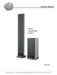
Software Customizing Guide UR12 Designer Software UR12 McIntosh Laboratory, Inc. 2 Chambers Street Binghamton, New York 13903-2699 Phone: 607-723-3512 FAX: 607-724-0549 Table of Contents Technical Assistance Table of Contents and Requirements .............................. 2 Technical Assistance .................................................... 2 Table of Contents ......................................................... 2 Requirements ............................................................... 2 Introduction ................................................................. 3 Software Features ......................................................... 3 If at any time you have questions about this McIntosh Software contact McIntosh Technical Assistance at: Chapter 1 McIntosh Laboratory, Inc. 2 Chambers Street Binghamton, New York 13903 Phone: 607-723-1545 Fax: 607-723-3636 Installing the Program .................................................. 4 Serial Ports Selection and Settings ................................. 5 Requirements Chapter 2 How to Connect the UR12 to the PC ............................. 6 Transferring Files and Data ........................................... 6 Workspace File and Data Types ..................................... 6 Uploading Data ............................................................ 6 Downloading Data ....................................................... 7 Chapter 3 Importing Command Sets ............................................. 8 How to Import MDL Files ............................................ 8 How to Import PDT Files .............................................. 8 How to Import LDT Files ............................................. 8 Buttons and Command Codes ....................................... 8 Learner Data/Command Codes ..................................... 8 How the Codes are Linked to the Buttons ...................... 8 Button Limits ............................................................... 9 1. The UR12 Upload Data Cable and Owner’s Manual, that are supplied with the UR12. Note: The following are available from the McIntosh Parts Department: Upload Data Cable is Part No. 171-437 Owner’s Manual is Part No. 040-774 3. A PC Computer with the following System Hardware and Software: 486, Pentium, or higher microprocessor 16 MB RAM or higher 16 MB free disk space Serial Port Windows 95, 98, ME or later Operating System Chapter 4 How to use the UR12 Designer Software ..................... 10 The Menu Bar ............................................................ 10 The Tool Bar .............................................................. 11 Device Tree and Button Template ................................ 11 How to Add a Button to a Device ................................ 12 Button Template Menu ............................................... 12 How to Import a Button .............................................. 12 How to Export a Button .............................................. 12 Workspace Display..................................................... 12 Button Manipulation .................................................. 13 Chapter 5 Drawing Buttons ........................................................ 14 Drawing Toolbar ........................................................ 14 How to Draw Buttons ................................................. 14 How to Replace Buttons ............................................. 14 Notes ......................................................................... 15 Copyright 2001 by McIntosh Laboratory, Inc. 2 Windows is a registered trademark of the Microsoft Corporation Introduction UR12 Designer Software is a powerful addition to the UR12 Preprogrammed and Learning Universal Remote Control from McIntosh. It allows you to quickly and easily refine the capabilities of your remote by customizing the UR12 Buttons, Screens and/or Pages. Using a PC and a serial cable connected to your remote, you can download new designs to the UR12 Remote and upload previously created page definitions for storage and manipulation. You can even import command sets from other UR12’s. Software Features l Change, delete, add, and copy buttons, to a total of 50 designs (each of which can be used many times on different page displays). l Add new buttons from the preset library; drag buttons from the library to Device Pages. l Drag ‘n’ drop buttons to new positions. l Change button labels, using two sizes of text at once. l Design new buttons with built-in drawing tools. l Zoom in to individual-pixel level for exact drawing. l Position buttons precisely with grid control. l Create and store extra buttons for future use. l Upload settings from the UR12, which can then be changed. l Maintain macros and punch throughs during the data transfer process. l Save uploaded page formats to disk. l Download new and revised page and button designs to the UR12. l Import command sets from the UR12 Designer Software. l Import page and button designs (command sets) from files created by other users. l Provide speedy operation through extensive use of mouse right-click. 3 Installing the Program McIntosh UR12 Designer Files are shipped in a compressed format. The files are automatically decompressed during the installation process. Therefore, to install and run McIntosh UR12 Designer Program on your computer, you must first run the installation program. The McIntosh Install Program installs the UR12 Designer Program on your computer. Installation The McIntosh UR12 Designer Install Program might not run properly if other programs are running including a virus-protection program. Stop all programs that are running during the installation of the UR12 Designer. After running the Install Program, you can restart those programs. The following procedure describes how to install UR12 Designer that was downloaded from the McIntosh Web Site, making sure to note the path where the UR12 Designer.exe file has been placed. Refer to the illustrations on this page. 1. Click the Windows START BUTTON and then click RUN. Note: An alternate method for installing is to use the Install/ Remove Program located in the Windows Control Panel. 2. Enter the path where the UR12 Designer.exe File is located, or click BROWSE BUTTON to locate it. 3. When the UR12 Designer.exe File is found, click OK. 4. The UR12 Install window will appear, click on Setup and follow the instructions on the screen. Note: The Install Program allows you to choose the Hard Drive/Folder Location and Start Menu Program Group for the McIntosh UR12 Designer Program. 4 Chapter 1 Serial Ports Selection and Settings Buttons, Screens and/or Pages you design are easily transferred to the UR12 Remote Control. Layouts that are stored in the UR12 Remote Control can be uploaded to the PC for manipulation and storage. Before data can be transfered between the UR12 Designer Software and the UR12 Remote Control, the PC used must have a spare Serial Port that can be made active with the correct port settings. Refer to figure 1. Start the McIntosh UR12 Designer Program by clicking on the UR12 Desktop Icon or from the Windows START MENU. Select TOOLS and then SETTINGS from the UR12 Designer Program Main Menu Bar. Refer to figures 3 and 4. Note: If the desired Serial Port, Com 1 is recommended, is not functioning it may require troubleshooting of the computer to resolve the Serial Port Conflict. Note: Changes may have to be made in the PC’s BIOS for making a Serial Port active, refer to the Owner’s Manual that was supplied with your PC and/or consult with the manufacture of the PC for assistance. Refer to figure 1 for Standard Com (Serial) Port Settings. Com Port Number Memory Location IRQ Number 1 3F8 4 2 2F8 3 3 3E8 4 4 2E8 3 Figure 1 Check to ensure that your PC’s Windows Port Settings conform to the following, refer to figure 2. 1. Click on the Windows Start Button. 2. Click on Settings. 3. Click on Control Panel. 4. Click on System. 5. Click on Device Manager. 6. Click on Ports. 7. Click on Communications. 8. Select the desired Com (Serial Port). 9. Select Properties. 10. Select Port Settings. Parameter Setting Bits per Second 115200 Data Bits 8 Parity None Stop Bits 1 Flow Control Xon/Xoff Figure 3 Figure 4 Figure 2 5 How to connect the UR12 to the PC Transferring Files and Data The UR12 Designer Program can transfer Device Data to and from the UR12 Remote Control. Transferring data is accomplished with the special cable provided with the UR12. 1. Connect the 1/8 inch stereo mini phone plug end of the Upload Data Cable to the jack on the bottom end of the UR12 Remote Control. Refer to figure 5. 2. Connect the DB9 connector end of the Upload Data Cable to the Serial Com Port on the computer. Operating Data and Button Information stored in the UR12 Remote Control can be saved to a disk using the UR12 Designer Software. By using UR12 Designer Program newly created files and Workspace/Data Files created by others can be transferred to the Remote Control. Buttons you design are easily transferred to your UR12 Remote Control. Layouts that you’ve created and taught on your UR12 can be uploaded to your PC for storage and manipulation. This chapter covers the following: • Introduction to Workspace files and Data types • Uploading Files from UR12 Remote to UR12 Designer • Downloading Files from UR12 Designer to UR12 Remote Note: Prior to downloading any new settings to the UR12 Remote Control, it is a good idea to upload your current settings and save them. This way there will always be a backup in case an operation fails, especially if some time has already been spent in programming the UR12 Remote Control. End View of UR12 UR12 Upload Data Cable Workspace File and Data types All button design and edit work is done within the Designer Workspace. The key resource tool for the Workspace is a single file format with “.mx” file extension. The program and command-code content held in the UR12 can be sent to the Designer Program and saved as a Workspace file. This action creates a transferable .mx Master File. This file is highly portable and anyone with the UR12 Designer can use it to reprogram their own UR12. For peace of mind, the designs and programming can be backed up or archived for later retrieval. The UR12 Designer Workspace is comprised of two types of data. “Operating Program Data” includes description, design, labels, macros, punch throughs, and placement of buttons. Refer to figure 6. Operating Program Data: Description Design Labels Macros Punch Throughs Placement of Buttons Figure 6 Computer with UR12 Designer Program “Learned Program Data” includes device codes and learned commands for individual buttons. Refer to figure 7. Learned Program Data: Device Codes Learned Commands Figure 7 Figure 5 6 Chapters 2 Uploading Data By first uploading your current UR12 Remote Control Command Settings to the Designer Program and then saving it, a valuable backup will be available for future use. To Upload Workspace data from your UR12: 1. Ensure that you have correctly connected your PC and using the supplied cable with the UR12. 2. On the UR12, select “Program Loading” from the System Setting Screen and the PC Interface Screen will appear. Refer to figure 8. 3. From the UR12 Designer Program Main Menu, click on Tools and select Upload or click on the Upload Icon on the Button Bar. Refer to figures 9 and 10. Figure 9 4. Press the Up Load Touch-button under Figure 8 Figure 10 “Operating Program” on the UR12’s PC Interface Screen. The Designer Software takes control and transfers the data from the remote control to the PC; a progress bar displays, indicating that the transfer is active. Refer to figure 11. Note: The UR12 Remote Control emits a beep when the process is complete. 5. When the Upload Process is complete, click OK. 6. From the Windows DiaFigure 11 log Box titled “Save As”, choose a name and save it. 7. To Upload Learned Data repeat steps 2 thru 5 and select “Learned Program” instead of the “Operating Program”. Refer to figure 12. Downloading Data The procedure for Downloading Data is basically the opposite of Uploading and Figure 12 allows for a newly created Command Set, or an earlier Command Set to be installed into the McIntosh UR12 Remote Control. 1. Ensure that you have correctly connected your PC to the UR12, using the supplied cable. 2. On the UR12, select “Program Loading” from the System Setting Screen and the PC Interface Screen will appear. 3. From the UR12 Designer Program Main Menu, click on Tools and select Download or click on the Download Icon on the ButFigure 13 ton Bar. Refer to figure 13. 4. Press the Down Load Touch-button under “Operating Program” on the UR12’s PC Interface Screen. The Designer Software takes control and transfers the data from the PC to the remote control; a progress bar displays, indicating that the transfer is active. Refer to Figure 14 figures 14 and 15. Note: The UR12 Remote Control emits a beep when the process is complete; the remote displays a test screen, indicating all systems are good. 5. When the Download Process is complete, click OK. 6. To Download Learned Data repeat steps 2 thru 5 and select “Learned Program” instead of the “Operating Program”. Figure 15 Note: There is no Learned Data in the default Workspace; you must upload your own data first. Otherwise, you will get an error message. The uploaded Learned Data is automatically integrated with the open Workspace file of which contains the Operating Program Data. 7 Importing Command Sets Buttons and Command Codes The UR12 Designer Program allows for the importing of the Operating Program Data from other compatable remote controls and their design software programs. How to Import MDL Files When it comes to designing Pages for the UR12 Remote Control, it’s all about the buttons. But before you begin designing your own screens, it’s a good idea to learn how command codes are associated with buttons, and how you can ensure that you maintain these links during the upload and download process. Note: Ensure that you have all file types associated with the command set you want to import: .mdl, .ldt, .pdt and button.ini. 1. Click File select Import from the menu. 2. Click on the MDL File Type. 3. Choose the .mdl file you want to import using the Windows File Browser. Note: Another Windows Dialog Box opens asking you to find and select the Button.ini File. 4. Find the Button.ini File associated with the .mdl file you selected, and click it to finish the import procedure. Refer to figure 16. C:\UR12 Operating System\Designer.mdl Figure 16 Notes: A Progress Bar displays during importing and upon completion the program returns to the Workspace screen. If there are any instances of file corruption with older buttons; the UR12 Designer Program will automatically repair any problems it discovers during the import process. How to Import PDT Files 1. Click File select Import from the menu. 2. Click on the PDT File Type. 3. Choose the .pdt file you want to import using the Windows File Browser. 4. Enter a name for a new Workspace File and click Save. How to Import LDT Files 1. Click File select Import from the menu. 2. Click on the LDT File Type. 3. Choose the .ldt file you want to import using the Windows File Browser. 4. Enter a name for a new Workspace File and click Save. 5. Make any changes you like to the buttons and page layout. 6. Save the file using File Save Workspace, or File Save As Workspace. 7. Download the data to your UR12, refer to Chapter 2. 8 Learned Data/Command Codes Here are a few key things to remember about Learned Data, or Command Codes, when customizing your Pages and Buttons: •Commands can not be added using the software. •When uploading Learned Data to the UR12 Designer, the command codes, macros, and punch throughs stick with the buttons. •When downloading Learned Data to your UR12 Remote Control, codes, macros, and punch throughs stick as well, unless you’ve moved the buttons. How the Codes are Linked to the Buttons During the transfer process, the preprogrammed codes are uploaded and stored as a Button Function Property. You can see the property associated with any button by rightclicking on a button, and clicking Function Property. Refer to figures 17, 18 and 19. If you click on any other function in the property sheet, a message will tell you Figure 17 which button the function is assigned to, Figure 18 and which Device Page the button is on. It will also inform you that any new buttons you have drawn are currently undefined. Chapter 3 Figure 19 Button Limits Even though the design interface allows buttons to be placed anywhere on the screen, there is a design limit built in to the software. You will get an error message with the following conditions: • A total of 56 buttons per device can be deployed: 14 per screen. Refer to figure 20. • While it may appear that buttons can be added anywhere on a Figure 20 Page, note the position of the default button command set carefully. With the exception of adding two buttons to the bottom row of each Page, beside the Last Page button, the software actually only remembers the location of the existing 12 buttons. Placing buttons off this “matrix” may lead to unusual results. Not that it cannot be done: just watch for anything out of the ordinary when you download the command set to the UR12. • UR12 Designer can maintain a maximum number of 50 distinct and individual buttons per Workspace. This is true whether the buttons are tiny or large, and is due to the memory structure of the UR12. If you try to add more than 50 buttons you will get an error message. More than 50 can be saved in the Workspace by adding them to the More Buttons Template. • Of the 50 buttons that can be deployed, eight are reserved for use by the software; this means that you can create up to 48 additional buttons per Workspace. The eight reserved buttons are displayed on the Buttons template in angled brackets when you first open the default Workspace, e.g.: <BW1>. 9 How to use the UR12 Designer Software This chapter describes the UR12 Designer Software Program which is made up of several parts including the Menu Bar, Tool Bar, Device Tree/Button Template Tabs and Workspace Display Area. Refer to figures 21, 22, 23, 24, 25, 26 and 27. Figure 23 Figure 24 Figure 25 Figure 21 Figure 22 The Menu Bar FILE: Load Default Model - Loads a default, blank workspace. New Button - Opens a blank Draw Window for new buttons. Open Button File - Loads a saved button *.btn file. Close Button File - Saves and Closes any new or edited buttons. Save Button File - Accessible when working with a *.btn file. Button Save As - Saves a *.btn file under a different name. Open Workspace - Loads a saved *.UR12 Workspace file. Close Workspace - Closes workspace and offers to save the file. Save Workspace - Saves your current work as a *.mx Workspace file. Save As Workspace - Allows you to save the Workspace under a different name. Import - Opens and converts MDL, PDT, and LDT filetypes from older versions of Operating Program. Recent files area - Lists the last few files opened. 10 Figure 26 Exit - EDIT: Undo (Ctrl Z) - VIEW: Toolbar Status Bar - Main Page Next page - Previous page TOOLS: Upload - Quits the program, offering to save the Workspace if it has not already been done. Cancels up to eight of your most recent actions, when drawing or moving buttons. Toggles Toolbar view. Toggles lower Status Bar view, indicating program resources available. Brings Main Page display to top. Opens next page of Device you are currently viewing. Cycles through open pages. Sets up the process of transferring data from your UR12 to the PC. Chapter 4 Download - Settings - WINDOW: Cascade - Tile - Close all - Sets up the transfer of new or saved Workspace data to the remote. Establishes which Serial port your transfer cable is connected to. Neatly stacks all open Page display windows. Opens all Page display windows to the same size, showing all. Closes any windows open in the Workspace display area. HELP: Typical Help menu items are listed here, including About information. The Tool Bar The Tool Bar offers quick access to some Menu functions, as well as some draw-specific tools for designing buttons. Let’s look at functions that are found on the Toolbar, and not available from menus: Text, Background - Adds text to the background display of any Page. Text, Label - Adds text for button labels. Text, Large - Selects the larger of two text sizes. Text, Small - Selects the smaller of two text sizes. Grid - Superimposes a grid against the Page display, for help when positioning buttons. The grid has an auto snap-to function which is active whether it is visible or not. time, and displays that information in the Device Tree. The left-most pane in the UR12 Operating Program window, referred to as the Device Tree, displays an explorer-like tree of all the Devices available to the UR12. Visible along the top of the Tree window are three tabs: Home, Buttons, and More Buttons. Refer to figures 28 and 29. DEVICE TREE: Using the tree is simple, just double-click on any Device Name; double-click on a page number to display that page of the Device system in the Page Preview window. The Device Tree display can be widened for viewing by clickdragging the mouse on the frame border. Figure 29 Note: Double-clicking a Device button when the Main Device Page is up opens Page 1 of the Device. Figure 27 Device Tree and Button Template Tabs When you start UR12 Designer the first time, the Device Tree loads a default.UR12 Workspace file. After that, the program remembers which Workspace was loaded last Figure 28 Figure 30 BUTTON TEMPLATES: Selecting either Button Tab opens the Button Template display. The Buttons Template displays all buttons registered for use with Designer. Refer to figure 30. Using this template, you can save new buttons, open them into the 11 Draw window for designing, or Move buttons to the More buttons template. The More Buttons Displays buttons not actively in use with the Designer program. This template is a storage area and the buttons may be saved for later use. For example, there may be few newly designed buttons that won’t be used in the current program, but can be stored by copying them to the Buttons Template. The Buttons tab template displays all buttons used in the open Workspace. Refer to figure 31. These buttons are active for designing Page screens for your UR12 Remote Control. The More buttons tab template displays buttons not actively used in the open Workspace, but available for use. This is where the extra buttons that have been designed are stored, or the buttons imported from previous iterations of the software, for later use. Some important functionality can be found on these templates through rightclicking. More imFigure 31 portantly, you can drag buttons out of the templates and place them right on any open Device Page. How to Add a Button to a Device 1. Open any Device Page from the Device tree. 2. Click the Buttons tab or More buttons tab to display the Buttons template. 3. Click and drag a button into position on the Device Page. Note: Buttons cannot be added to the Main Device Page in this manner. Button Template Menu The Button Template Menu is accessed by right-clicking on any button. This section describes the functions available from this menu. 12 EDIT Clicking the Edit menu opens the button to a Button Draw window, where you can edit it using the Draw tools menu on the side of the display. A Drawing Window is opened by double-clicking on any button. For details on using Draw tools, refer to page 14. IMPORT Any *.btn file can be added to the Button template; up to 50 buttons in all can be used at one time. If you need to import or create more than 50 buttons, add them to the More buttons template instead. How to Import a Button 1. Right-click anywhere on the Buttons template. 2. Click Import button file (*.btn). 3. In the Open dialog box, click the *.btn file you want; the button is added to the template. Note: The same button can be opened to the template more than once. EXPORT Any *.btn file can be exported, or saved to disk. How to Export a Button 1. Click the Buttons tab to display the Buttons template. 2. Right-click the button to export. 3. Click Export as button file (*.btn). 4. Save the button. Send to “More buttons” - Send to More buttons moves the selected button to the “More buttons” template. Delete - Clicking Delete deletes the button selected, after verifying that this is what you want to do. Rename - Click Rename to access the button label and change the name. Also, you can click on the button title displayed in the template; after a short pause, it becomes available for edit. Properties - Clicking Properties allows you to rename a button’s visible label and its internal program label. Workspace Display The Workspace display area of UR12 Designer is the basic holding area for working with Device Pages and using the Draw tools to edit buttons. Navigating the Workspace is performed by Double-clicking on any Device Page in the Chapter 4 con’t Device Tree, opens the Page in the Workspace, or brings that Device Page to the top of the stack. Refer to figures 32 and 33. When multiple Pages are open, use the Cascade or Tile buttons in the Window menu, or the buttons on the Figure 32 Toolbar, to help sort the display windows. Doubleclicking on the Main Device Page opens that Device’s Figure 33 Page 1 and brings it to the top of the stack. Use the Arrow buttons to cycle through pages in an individual device; if they are not open, this will open them. Refer to figure 34. Figure 34 • Turn on the Grid for guidance when positioning buttons. The grid snap-to is always on even when it is not displayed; hold down the Alt-Key to drag buttons without the snap. Refer to figure 36. Figure 36 • For Nudge and Fine Nudge movements, use the cursor keys to nudge the buttons in small increments. Hold down the Ctrl key at the same time to invoke Fine Nudge, which moves a button one half the distance of regular Nudge. Double-click on the Last Page icon to cycle through the Pages open for that Device; if they are not open, this will open them. Once you have made all your changes, you can download the new Workspace to your UR12 Remote Control. Refer to figure 37. Figure 37 Button Manipulation The Page Preview area of the Workspace displays the currently selected Device Page screens. Apart from actually designing buttons, this is where most of the activity takes place. Here, you can change buttons, change labels, and copy and move buttons around to suit your own requirements. This is the key feature of UR12 Designer, and what makes it so desirable for owners of the UR12 Remote Control. This is what can be preformed in the Page Preview Window: • Drag a button from either Button template to add it to any open Device Page. • Right-click any button on any Page, and instantly move it to another Page in the same device, or Delete it Figure 35 altogether (when you delete a button, the label is deleted as well). Refer to figure 35. • Right-click on any button on any Page, and discover what command is assigned to it. 13 Chapters 5 Drawing Buttons The UR12 Designer includes a basic set of drawing and erasing tools for creating your own series of buttons, which can download for use on the UR12 Remote Control. Buttons can be thematic in nature, or randomly designed. Buttons can be shared with other users individually as .btn files, or in groups, using the Workspace .mx File Format. Drawing Toolbar The tools used to draw and edit buttons are available from a special Draw Toolbar, refer to figure 38. When you open a button window as New or as Edit, the Draw Toolbar is available on the right side of the screen and its functionality is selfexplanatory. There are two eraser buttons at the top of the toolbar are different “strengths”: the large-nibbed eraser removes nine pixels at once; the pointy-nibbed eraser erases one pixel per click. Right-clicking on a pixel acts as a “quick-erase”, with the eraser assuming the Figure 38 shape of the tool in use. Change the color applied by a tool by clicking one of the four color wells at the bottom end of the toolbar. How to Draw Buttons Drawing new buttons from scratch is a simple process in terms of using the software, the rest is up to your own creative talents. To draw a new button perform the following steps, refer to figures 39 and 40. 1. Click File and New Button. A blank Button Draw window opens. 2. Click any of the tools in the Draw Toolbar Figure 39 to the right of the Draw window, and create a new design. 3. When finished, click File > Close Button File to invoke the Button Save As dialog box. 4. You are offered the following choices: A.Yes, save as “More buttons”: saves your work to the More buttons template for “storage”. B. Yes, save as “Buttons”: saves your work to the Buttons template for immediate use in the program. C. Yes, save as file (*.btn): saves your work to disk as a discrete button file for later use. D. Name as—Icon name (visible name), enter a name that will identify the button on the templates. 14 Figure 40 E. Name as—Default button name, enter the same name or a different name to identify the button when you drag it into position on a Display Page. Note:The same Button Save As dialog box opens if you click File, Close Button File. EDIT BUTTONS Use the same tools when editing existing buttons, or making changes to new buttons, as you use when creating new buttons (above). But instead of opening a new Button Draw window, simply double-click on any button (on either Buttons template). How Replace Buttons Replacing a button on a Device Page with another button from the Button templates is a “snap”. 1. Open a page in the Device Tree. 2. Click the Buttons or More buttons tab. 3. Click and drag any button on top of an existing button. When it is properly positioned, by matching the upperleft corners of the two buttons, the ∅ symbol disappears and a blue highlight box indicates that you can correctly drop the button. Notes 15 McIntosh Laboratory, Inc. 2 Chambers Street Binghamton, NY 13903