1
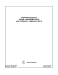
llllllIllllllllllllllllllllllllllllllllllllllllllllllllllllllllllllllllllll
_
USOO5267311A
Ulllt?d States Patent [19]
[11] Patent Number:
Bakhoum
[45]
Date of Patent:
5 9 267 9 311
Nov. 30, 1993
[54] INTELLIGENT DISKETI‘E FOR SOFTWARE
PROTECTION
Pagemaker, Aldus; User Manual; Dec. 1987; p. 1-26;
Aldus Corp., Seattle, WA.
[76] Inventor:
P?mary Examiner—stephen C‘ Buczmski
[57]
ABSTRACT
Ezzat G. Bakhoum, PO. Box 2818,
Durham, NC. 27715-2818
'
A device for protection of computer software installed
[211 App!’ No" 986’667
-
_
particularly a device of such type that is embedded
[22] Flled'
[51]
[52]
[ss]
on hard disks against unauthorized copying and use, and
Dec' 8’ 1992
inside an ordinary diskette cartridge.
Int. c1.5 ...................... .. H04L 9/00; G1 1B 15/04
US. Cl. ......................................... .. 380/4; 360/60
Field of Search ........................ .. 380/3, 4; 360/60
The deviee depends mainly in its Operation on e VLSI
mierocontroller embedded inside the diskette and inter
faced to a read/write head placed in contact with the
surface of the ?oppy disk. In connection with such
[56]
References Cited
U S PATENT DOCUMENTS
device, a method is described to prevent an executable
code from being installed on more than one machine,
' '
4,446,519
even if several machines are present in the same work
5/1984 Thomas .
gggzfrg at a!‘ '
4:858:O36
place.
360/60
8/1989 Ginkel _"""""""""""""""""" "
The device of the invention is very convenient for the
software user. Together with the convenience, it suc
4,959,861 9 /1990 Howlene _
cessfully achieves two main objectives: ?rst, preventing
4,980,782 12/1990 Ginke] _
5,122,912 6/1992 Kanota et a1. .
the software from getting transferred and used over
seas, and secondly, preventing the software from get
ting transferred to a friend or colleague in the same
OTHER PUBLICATIONS
workplace.
Pagemaker, Aldus; Ref. Manual; Dec. 1987; p. 2-18;
Aldus C0rp., Seattle, WA.
100
36 Claims, 6 Drawing Sheets
BatltgeariesBattery
Compartment
112
Microcontroller
US. Patent
Nov. 30, 1993
Sheet 1 of 6
5,267,311
B attery
Compartment
1/04
124
/
FIG.
1(a)
1 12
10<\
114 R/W Head
;L//////|/////§'
L___J
R/O Head 116
Microcontroller
US. Patent
Nov. 30, 1993
Sheet 2 of 6
5,267,311
89.9
UserMaSk
01100010
202
Allocation
Mask
%
204
Certification 3
Byte
206
1 1 1 1 () O 1
US. Patent
Nov. 30, 1993
Sheet 4 of 6
5,267,311
400
404
T
402
T
T
Programing Code
(
START
)
Run by Vendor
Write Mask
to
’\410
Track 108
Activate R/W
Head to Read
8 bytes
@408
Erase
Track 108
“412
406
T
Executable Code
414
Run by User
8
Write
Test Password
to Track 108
K416
Fetch a
Test Password
from Track 108
______________ _
Data Masking/
Allocation
(420
Read
Confirmation
Write
Confirmation
Password
from track 108
Password
to Track 108
FIG. 4
418)
>
US. Patent
I
Nov. 30, 1993
502
Sheet 5 0f6
5
l
V
SYNC Bits
5,267,311
J
Stop Bits
Data
FIG. 5
602
Diskette
Present‘?
606
Create SVF
Proceed
U.S. Patent
Nov. 30, 1993
Sheet 6 of 6
5,267,311
700
734
Microcontroller
730
SuperS' ft
Tampering with
this seal will
terminate your
license agreement.
Ser.No. XXXXXX
Batteries 722
736
FIG. '7
732
738
1
5,267,311
2
ing by professionals. Further, once the executable code
INTELLIGENT DISKE'I'I‘E FOR SOFTWARE
PROTECTION
is installed on a hard disk (as is usually the case), such
protection methods are worthless.
It is the objective of the present invention to provide
BACKGROUND OF THE INVENTION
5
a device for preventing the use of stolen software. Since
1. Field of the Invention
“copy-protection” techniques have failed to prevent
This invention relates to a device for protection of
software
theft, the present invention rather prevents the
computer software installed on hard disks against unau
execution of the code on the CPU, unless the device of
thorized copying and use, and particularly a device of
the invention is present in the floppy disk drive of the
such type that is embedded inside a diskette cartridge.
computer.
2. Important Notice to the Reader of this Patent Ap
plication
It is another objective of the present invention to
This patent application describes a device of a rela
provide a method for software protection which is ex
tively simple physical structure. However, the mecha
tremely convenient for the end user, by featuring an
nism by which the device performs its function is new
ordinary diskette cartridge that can be easily loaded in
and of considerable complexity.
the disk drive of the computer each time the software is
Every effort has been made to keep the speci?cation
run.
clear and understandable. However, patience and con
It is ?nally the ultimate objective of the present in
centration in reading are necessary for understanding.
vention to provide a method and device for software
The section titled “Software protection in the same
workplace” is the most important section of this appli
protection which will prevent an executable code from
cation and should be read with special care.
being installed on more than one machine, even if sev
3. Description of the Related Art
eral machines are present in the same workplace.
Each year, billions of dollars worth of American
Other aspects and features of the invention will be
software is stolen overseas. This not only hurts the
more
fully apparent from the ensuing disclosure and
American software developers, but is also extremely
appended claims.
damaging to the U.S. economy, one of its key elements
of strength being technology.
SUMMARY OF THE INVENTION
In one country half-the-way around the globe, I saw
a software merchant advertising: “We sell the latest
In a broad aspect, the present invention relates to a
version of AutoCad for 15 pounds”.
device for preventing unauthorized use of software,
Software theft has become a widely spread phenome
comprising:
non in recent years due to the extreme ease with which
a diskette cartridge comprising a housing and a rotat
data can be transferred among magnetic media, and the
lack of successful means for preventing unauthorized
data transfers.
a microcontroller embedded inside the housing of
It is the object of the present invention to provide
such successful device for preventing software theft.
The device is an intelligent diskette that accompanies
at least one magnetic head interfaced to said mi
crocontroller, and placed in contact with the sur
able magnetic media placed inside the housing;
said diskette;
each set of executable diskettes. Without the presence of
that device, execution of the code on the CPU is impos
sible.
face of the magnetic media.
Whereby handshaking is accomplished by means of
exchanging signals between the embedded microcon
In the prior art, several techniques have been devel
troller
and the host computer, via the magnetic media of
oped in attempts to prevent software theft, none of
which has been completely successful to date. The ?rst 45 the diskette.
attempt was to alter the standard format of storing ?les
on the magnetic media to prevent unauthorized duplica
tion. But rapidly programs were developed to break this
copy-protection scheme. Another attempt was to pro
vide an intelligent circuit that connects to the computer
via a serial port or internal bus. Unfortunately, how
ever, such circuits can easily be duplicated by profes
sionals, as they usually depend on a ROM which can be
duplicated by various means. Further, the use of an
additional piece of hardware for each software program
is very inconvenient for the user.
A third technique is described in U.S. Pat. No.
4,734,796 issued Mar. 29, 1988 to Grynberg et al, which
shows a method for preventing unauthorized copying
of diskettes based on inducing surface defects at known
locations on the magnetic media. A still further tech
nique is shown in U.S. Pat. Nos. 4,858,036 and 4,980,782
issued Aug. 15, 1989 and Dec. 25, 1990, respectively, to
Peter Ginkel, which depends on the use of magnetic
materials possessing high coercivity to prevent duplica~
tion of diskettes.
Unfortunately, however, the techniques of those
three patents are still vulnerable to unauthorized copy
BRIEF DESCRIPTION OF THE DRAWINGS
FIG. 1(a, b) is a schematic representation of an intelli
gent diskette according to the present invention, com
prising a microcontroller and two magnetic heads.
FIG. 2 shows an 8-byte user mask to be programmed
and stored inside the microcontroller of the diskette.
FIG. 3 is a block diagram illustrating the main princi
ple of operation of the microcontroller of the present
invention.
FIG. 4 is a ?ow chart illustrating the preferred hand
shaking method between the intelligent diskette and the
host computer, according to the present invention.
FIG. 5 shows a synchronization method for data
transfer, according to one embodiment of the invention.
FIG. 6 is a flow chart illustrating steps to be taken by
an executable code, for protection against unauthorized
65 use by different users in the same workplace.
FIG. 7 is a schematic representation of an intelligent
diskette, according to a different embodiment of the
present invention.
3
5,267,311
DETAILED DESCRIPTION OF THE
INVENTION, AND PREFERRED
EMBODIMENTS THEREOF
Basic Structure and Handshaking Techniques
The present invention mainly features an intelligent
4
gram, but no data, being stored on the diskettes. Each
software vendor will then be able to program his intelli
gent diskettes without the risk of letting the manufac
turer have access to critical data.
5
Reference is now made to FIG. 1(a) in the drawings.
FIG. 1(a) shows an ordinary diskette cartridge 100
device that works in conjunction with an ordinary
which may be a 3.5" or 5.25" type diskette. The jacket
?oppy disk. An executable code, supplied by a software
or housing of the diskette, 102, preferably made of hard
plastic, is shown with a broken section on the right
vendor, will check for the presence of such device
inside the ?oppy disk drive of the computer, and should
hand side, thereby exposing the internal detail to view.
The ?oppy disk 104 is shown as rotating counterclock
not execute if the device is not present.
In conjunction with such intelligent diskette, a
method will be further described which will enable the
executable code to “recognize” the host computer it
wise in the ?gure, with the read/write head of the host
computer 106 being positioned over one particular
track 108 (the movable head 106 of the host computer is
not a part of the diskette and is shown in FIG. 1(a) only
was ?rst installed on. This will prevent the code from
unlawfully getting installed on several machines in the
for clarity). Inside the housing, special provisions are
same workplace, with the intelligent diskette being used
made to embed a custom-made CMOS microcontroller
to activate all such machines simultaneously.
110.
The handshaking between the host computer and the
The microcontroller 110 is connected to a thin ribbon
intelligent diskette will be accomplished by means of 20 connector 112, carrying interface signals to a ?xed
polling. As a preferred embodiment of the present in
read/write head 114. The head 114 is positioned over
vention, the executable code running on the host writes
the particularly-chosen track 108, and is in contact with
a special stream of bits on the magnetic media of the
the surface of the ?oppy disk. The function of head 114
diskette. The microcontroller inside the diskette, in
response to such stream, issues a password, which is 25 is to read and write handshaking information. The mi
crocontroller is similarly connected with a connector
written on the same track of the ?oppy disk, to be later
118 to a fixed read-only head 116 positioned on the
read by the host computer and passed to the executable
other side of the ?oppy disk, such that the disk is sand
code as a certi?cation of the presence of the diskette in
witched between the two heads, as shown in FIG. 1(b).
the drive.
Clearly, such password must be different each time 30 The function of the read-only head 116 is to read syn
the intelligent diskette is “polled”; for if the password is
chronization pulses from a track 120 on the lower sur
constant, it would be a simple matter to professionals to
face of the disk. The synchronization track 120 (the
function of which will be more emphasized later) serves
pick up the password by various means, including direct
as a “clocking” means for the microcontroller. The
reading from the diskette, and later program the same
password on a different intelligent diskette supplied by 35 heads 114 and 116 are preferably embedded within the
layers of cushioning material that usually surround the
the same manufacturer. Therefore, the intelligent dis
kette of the present invention must provide a sequence
?oppy disk.
of passwords, such sequence being known only to the
It will be therefore apparent that one particular cylin
executable code with which the diskette is intended to
der in the diskette will be designated to hold two types
work.
of information, on two different tracks: a data track 108,
(My own experience as a professional Engineer has
and a synchronization track 120.
taught me that a severe mistake is to assume that a given
The microcontroller is finally connected to a set of
new technology is sophisticated enough so that it is
thin Lithium batteries 122, such batteries being installed
inside a cavity 124 in the housing. The cavity 124 is
accessible from the outside for the purpose of replacing
the batteries. (The intelligent diskette should be sup
unvulnerable to copying by professional technology
pirates. I have seen such individuals in several countries 45
around the world. Any technology which can be dupli
cated or stolen by some means will be duplicated and
plied to the software vendor with no batteries installed.
stolen. My objective in the present invention is to pro
The batteries should be installed by the software vendor
vide a protection method which by no means can be
duplicated).
In accordance with the present invention, a technique
for the generation of a sequence of passwords will be
50
prior to the programing of the handshaking code).
Normally, a microcontroller, which is in most in
stances a special-purpose microprocessor, comes
equipped with a PC (program counter), an internal bus,
a
microcode, etc.; in order to allow the fetching and
ming” of few bytes of data, to be stored in internal
registers inside the microcontroller used in conjunction 55 execution of instructions from a ROM. Such elements,
however, are not required in the microcontroller 110 of
with the diskette. Such programing is normally done by
the present invention. Instead, all control functions of
the software vendor, and has the advantage of storing
the microcontroller 110 will be implemented by a spe
critical data on RAM, rather than ROM; as it is widely
cial logic and control circuit, which demands much less
known that ROMs can be accessed in virtually any
space on a VLSI chip. Such circuit, in fact, will mimic
system or device, and the contents of the ROM can be
a “control program” directly on silicon, without the
obtained by various means. It is true that a ROM can be
requirement for formal architecture. The structure of
built into the microcontroller at the time of fabrication
the proposed microcontroller will be explained in some
of the chip, without exposing the data bus for external
detail later.
access; however, the programing must be done by the
Now, with the basic structure of the device being
manufacturer in this case. The advantage of using RAM 65
described. Such technique will require the “program
is to allow one or more manufacturers to produce intel
understood, we shall turn our attention to the main
ligent diskettes in mass quantities and supply such dis
problem of the present invention, that is, how the intelli
kettes to software vendors, with only a control pro
gent diskette should generate the sequence of pass
5
5,267,311
6
words, and how the executable code should be able to
indicate its presence. Clearly, the decoding method
recognize such sequence?
must be known to the executable code in order to verify
First of all, in order to facilitate the “commercial”
handshaking between the manufacturer of intelligent
diskettes and the large number of software vendors, it is
preferable that the diskette be supplied with a standard
control program, as mentioned previously (in our case,
such control program will be a “hard-wired” program).
This will enable each software vendor to program his
own handshaking method, by writing to the diskette an
ordinary ?le containing such information, while the
control program handles the transfer of data from the
magnetic media of the diskette to the internal registers
of the microcontroller (this procedure will be explained
later in further detail). Without the presence of such
control program, the software vendor cannot simply
“write” the handshaking information to the diskette as a
file. In fact, the microcontroller must be supplied with a
standard architecture (i.e., with a program-counter,
internal bus, etc.), and the software vendor has the extra
burden of doing low-level programing. Such low-level
programing may not be done optimally; and most im
that the decoding was done correctly. The decoding
method must be programmed by the software vendor
and stored in the microcontroller’s registers prior to the
distribution of software.
I shall now explain the preferred embodiment of the
present invention. Referring to FIG. 2, a set of registers
200, consisting preferably of 8 registers, are used to
store two different types of masks: a “User mask” 202,
consisting of 4 bytes, and an “Allocation mask" 204,
consisting of 2 bytes. The remaining 2 bytes are used for
a special purpose which will be explained later. An
incoming test password, consisting of 4 bytes, will go
through a bitwise INVERT operation, which is deter
mined by the user mask (in the example shown in FIG.
2, the second, third, and seventh bits in the ?rst byte of
the test password will be inverted, while the remaining
bits in that byte will be left unchanged). A test password
20 may equally be NORed or NANDed with the mask;
however such operations are not recommended, since a
test password consisting of all 0's or all l’s can some
times fool a logic system based on these operations. In
any case, the operation must be ?xed and de?ned by the
portantly, cannot be done unless the internal bus of the
microcontroller is exposed to public use; which may not
protect the critical data inside the registers, once the 25 diskette manufacturer. Such preliminary operation has
registers are programmed. We therefore see that the
the purpose of hiding or “masking” the sequence of bits
existence of a standard control program not only saves
in the test password. Now, since any logic operation, if
space on the VLSI chip, but also prevents lots of trou
known, can be reversed, further masking is necessary.
ble.
The preferred embodiment is to further hide the result
With the control program being known, how a hand 30 ing 4 bytes among several bytes of irrelevant data. Since
shaking method between the intelligent diskette and the
the data in the resulting 4 bytes will be unknown after
the masking, it will be impossible to distinguish such
host computer should be de?ned to the microcon
data from irrelevant data in a long sequence of bytes
troller?, and how a sequence of passwords should be
generated? Clearly, the control program itself must
(this is similar to card game, where several playing
handle the generation of such sequence, which must be
different for each user. The ?rst idea is to use a different
cards are being displayed, with the locations of the
signi?cant cards being known only to one player). Such
bytes, and which can be used as a “seed” or basis for
is the function of the allocation mask 204. Each half
byte in the allocation mask indicates how each corre
generating a sequence. However, an important problem
sponding byte in the masked password should be allo
“mask” for each user, which may consist of several
arises in such case: how the executable code can keep 4-0 cated within a stream of 16 bytes. In the example of
track of the “order” in such sequence? i.e., how to pre
vent the executable code from getting “fooled” by pass
ing to the code an old password in the sequence? One
possible solution, which will prove to be unsuccessful, is
FIG. 2, the ?rst byte of data should occupy the 16th
position in a stream of 16 bytes, the second byte of data
should occupy the 4th position, the third byte of data
should occupy the third place in the stream, and the last
to maintain a “counter” as a ?le on the hard disk, or else 45 byte should occupy the 10th position.
As a result, the executable code running on the host
computer issues a test password of 4 bytes and receives
a stream of 16 bytes, only 4 bytes of which are meaning
?le each time the code is run to “mark” the most re
cently used password. Unfortunately, such scheme will
ful. The number of possible allocations in such masking
not be successful because a clever user can simply pick 50 scheme is given by l6l/ 12!, or a number in the order of
up a password, together with the password ?le (or
43,000. An important question now is: how the irrele
vant data should be generated? Clearly, we cannot sim
counter ?le) that matches this password, and write that
?le to the hard disk each time before the software is run.
ply use a random bit generator on the chip; for if a
We can amuse ourselves by thinking of other alterna
random bit generator is used, a simple trick would be to
tives for solving this problem; but since this may take 55 pass the same test password to the intelligent diskette
twice, and simply observe the 4 bytes in the resulting
several pages of government paper and several hours of
precious reader time, I shall rather state directly that
sequence which will remain unchanged. Therefore, a
such problem is unsolvable. This will become clear if
“pseudo-random” bit generator must be used. Such
pseudo-random bit generator must be driven by the test
we simply observe that a microcontroller equipped
with batteries has means to maintain a “memory”. Such
password itself, so that a repeated test password will
result in the same l6-byte pattern. However, another
memory is not available for an executable code, except
pitfall must be avoided here: clearly, the 16-byte pattern
on the magnetic media of a disk.
must not be completely predictable; for if such pattern
The handshaking problem will truly be solved by
is completely predictable for a given test password, we
using a “two-way” handshaking protocol, rather than
to maintain the sequence itself as a long list in a ?le
(which may be coded by some means) and update that
sequence generation. In a two-way handshaking proto 65 have not solved our problem. How this can be done?
col, the executable code sends a “test” password to the
The solution can be seen in FIG. 3. FIG. 3 shows a
intelligent diskette. The diskette, in turn, “decodes” the
pseudo-random bit generator 302 comprising an XOR
gate 304 and a feedback shift register 306 (this pseudo
test password and issues a “con?rmation” password to
7
5,267,311
random bit generator is a well known circuit, and is
described more fully in Principles of CMOS VLSI design,
by Weste and Eshraghian, Addison Wesley, 1985, page
266). For generating a pseudo-random sequence of 16
bytes, a 7-bit shift register is required. Now, how to
select such 7 bits for initializing the shift register? Since
the test password itself must drive the pseudo-random
generator, we can simply route a portion of the masked
password to shift register 306 in order to start the 16
byte sequence (it is essential to use a portion of the
“masked” password, not the original password, to avoid
generating a predictable sequence). But before we go
any further, we will have to mention a serious draw
back of the pseudo-random bit generator 302: it is true
that only 7 bits are required to obtain a l6-byte se
quence, however such circuit can only generate 128
distinct sequences. This can be seen from the fact that a
7-bit shift register can only have 128 different initial
states. The problem now is clear: 128 is a very small
number. The 128 different sequences could be even
written on a single sheet of paper and compared visually
to the output sequence. For that purpose, it is preferable
8
chronization track 120), execution of the control code
actually starts when the disk starts rotating.
The ?rst step 408 in the control program activates the
read/write head 114 in order to read the sequence of 8
bytes. Such sequence of is ?rst written in a serial fashion
by the host’s read/write head 106, and then captured by
the ?xed head 114 inside the diskette. Clearly, such
write~read procedure requires a special synchronization
technique in order to enable the head 114 to recognize
the data. Such technique will now be explained.
First, the programming code 404 running on the com
puter reads the DIR (Directory) and FAT (File Alloca
tion Table) on the floppy disk. Based on prior informa
tion recorded in the DIR and FAT areas, and supplied
by the manufacturer, the magnetic head 106 of the com
puter is directed to track 108, and seeks the ?rst sector
in that track. The programming code then starts to
write the sequence of 8 bytes as an ordinary ?le. Such
?le will contain synchronization information beside the
20 mask information. FIG. 5 shows a write-read synchro
nization method as a preferred embodiment. As shown
in FIG. 5, the host’s magnetic head ?rst writes a long
sequence of Sync bits 502, consisting of alternating
to make the shift register 306 4-bytes long, and route the
High’s and Low’s, as shown. The microcontroller in
entire masked password to the shift register (this task
will be explained in more detail later). An initial state of 25 side the diskette, now being clocked by the lower syn
chronization track 120, detects the Sync bits on upper
4 bytes will result in 232, or some 4000 million distinct
track 108, and prepares to capture the S-byte data. The
sequences. But, have we solved our problem? de?nitely
Sync bits terminate with a sequence of two Stop bits
not. It is true that such large number of sequences can
504, and then the data 506 starts. Clearly, the read/write
not be written on a sheet of paper, however, a computer
simulation can be done to compare “on the fly” all 30 head 114 must be interfaced to a set of 8 shift registers
i.e., the masked password. What, then, is the de?nite
for storing the mask information.
Now, with the 8-byte data being transferred to the
microcontroller, the primary objective of the program
measure of security in such a system? The de?nite mea
ming code has been accomplished (step 410). The pro
possible sequences to one particular sequence captured
from the diskette, and hence determine the initial state,
sure of security is the 4 bytes of the unmodi?ed masked 35 gramming code must now erase track 108 (step 412) by
password, which will be “mixed”, or allocated in un
known places within the output sequence, thereby mak
ing the sequence itself undistinguishable (we recall,
again, the idea of the playing cards). If space on the
VLSI chip permits, a mask of more than 4 bytes can be
used for added security.
It should be noted that, for proper protection, the
user mask must not be “sparse" in nature; for if a user
mask like, for example, 00 . . . 01 is used, we have simpli
writing some irrelevant information to that track
(clearly, the data should not remain on the disk). The
control code then proceeds to the next phase (user
phase) and attempts to fetch a test password from the
disk (step 414) when the disk starts rotating. As shown
in FIG. 4, the executable code 406 writes Sync pulses to
track 108, followed by a test password (step 416). By the
same write-read mechanism explained previously, the
?xed head 114 inside the diskette fetches the test pass
?ed the job for a technology pirate (this can be seen if a 45 word, and the Data Masking is done on the ?y in step
414 (this procedure will be explained in detail later).
test password of all O’s or all l’s is used with such a
The microcontroller then writes the l6-byte con?rma
mask. In this case, the resulting sequence will be near
tion sequence to track 108 (step 418). Later, the execut
the very beginning or the very end of the list. A famous
able code reads and analyses the con?rmation sequence
example in everyday’s life is the combination look. We
never set the combination of such locks to be 000 or
(step 420). A point of interest is in order here: the mi
crocontroller inside the diskette must not be allowed to
999). This is usually not a problem if the software ven
write over the header of sector 2 on track 108; i.e., if the
dor has to select 4 different bytes for each user, or 232
processing delay is large, the microcontroller may re
combinations in total, since any software vendor is not
quire more than 4096 clock pulses to accomplish its
likely to have such huge number of customers.
Referring now to FIGS. 1,3,4 and 5, the functionality 55 mission. That number, (4096: 512 X 8) is the number of
bits in sector 1, which is composed of 512 bytes. As
of the intelligent diskette will be explained in detail:
sector 1 rotates past the magnetic head in the diskette,
FIG. 4 shows a ?owchart 400 of the control program
the microcontroller receives 4096 clock pulses. How
402 which will be “hard-wired”in the microcontroller’s
ever, writing over the header of sector 2 is very unlikely
circuitry. In FIG. 4, the control program is interacting,
?rst, with the programming code 404 that should be run 60 to occur because the microcontroller reads some Sync
pulses, followed by a 4-byte sequence and then writes
by the software vendor in order to transfer the 8 user
Sync pulses, followed by a l6-byte sequence; which, in
bytes to the micro-controller inside the diskette, and
total, is far less than 512 bytes. Nevertheless, such pro
then interacting with the testing code 406 (a part of the
visions must be taken in the design in order to allow the
user-executable code). When the diskette is supplied to
the software vendor, the vendor installs the batteries 65 executable code to read the con?rmation sequence as a
part of an ordinary ?le.
inside the diskette, and the microcontroller starts exe
Referring now to FIG. 3, I shall explain the basic idea
cuting the control program 402. Since the microcon
behind the proposed Masking/Allocation technique.
troller is actually clocked by external means (the syn
9
5,267,311
10
Rather than laying down a complex logic circuit, the
idea will be explained in “block diagram” form. An
incoming test password 308 is fed serially to a circuit
310 for detecting Sync pulses and for performing con
of each of the four half-bytes in the Allocation Mask. If
the two values match, one of the trapped bytes in the
four cyclic shift registers will be routed to the output,
trol functions upon such detection. When the two stop
bits are detected at the end of the Sync pulse sequence,
the circuit 310 starts routing the user mask bits, serially,
plexer 332. The control unit 330 features a special out
put line 334 which may carry a signal of either 0 or 1. If
to an XOR gate 312, where the incoming bits of the test
password are properly inverted (the reader can verify
that an XOR gate will indeed perform an INVERT
operation, determined by a mask, where both the mask
bit and the data bit are given as inputs to such gate). At
the same instant, an Enable signal is issued to a coun
ter/decoder unit 314, having four active-low outputs,
by means of a proper selection signal issued to multi
one of the trapped bytes in the cyclic registers is being
selected, the signal on line 334 is l and the output of
multiplexer 332 appears at the output of multiplexer
336. If, however, none of the trapped bytes is selected,
the signal 334 is O and the output of the pseudo-random
bit generator is selected by the output multiplexer.
We will ?nally have to mention a deficiency of the
XOR gate 304 used in the pseudo-random bit generator.
labeled Inhibit1-Inhibit4. The counter/decoder unit rd 5 It can be observed that, if a particular test password and
its complement are used, the two resulting sequences
means of which the Inhibit outputs are activated se
will be identical, due to the nature of the XOR gate.
quentially, one every eight clock pulses. As a result,
However, the four hidden bytes of the masked test
when the Enable signal is received, Inhibit] becomes
password will not be identical in the two sequences. In
active for a duration of 8 clock pulses, during which the
fact, such four bytes will be complemented in the sec
?rst byte of the masked password 318 is transferred to a
ond sequence, which will allow easy identi?cation of
cyclic shift register 320, of which a total of 4 registers
those bytes. To avoid this trap, a different logic func
exist. The cyclic register 320 is equipped with a control
tion, such as a NAND, can be used instead of the XOR
unit 322, and similarly all other cyclic registers. The
gate 304. However, the logic function does not neces
control unit 322 has the purpose of detecting an active 25 sarily have to be simple. In fact, such logic function can
Inhibit signal and inhibiting the cyclic register from
be arbitrarily complicated, and may involve one or
operating in a cyclic mode. When Inhibit] becomes
more bits of the shift register 306. Further, such logic
function must in practice he kept secret by the diskette
active, for instance, the register 320 does not operate in
manufacturer.
a cyclic mode, but instead the ?rst byte of data is trans
314 is clocked by a “divide-by-eight” circuit 316, by
ferred to the register. During the following period of 8 30 What are the extra burdens on the software vendor in
view of such complexity? Nothing. The software ven
clock pulses, Inhibit2 becomes active, while all the
dor merely has to prepare 8 different bytes of data for
others are inactive. As a result, the control unit 322
opens the feedback path, and register 320 operates in a
each user, which will be ?rst incorporated into the
executable code and then loaded into the intelligent
cyclic mode; while the next cyclic register, 324, accepts
the second byte of the masked password; etc. When the 35 diskette (the function of the last two bytes of data has
not been yet explained). The intelligent diskette will
counter determines that 4 bytes have been received, the
then be distributed with the software. The executable
control unit 310 removes the Enable signal, and the
code does not necessarily have to be modi?ed in order
Inhibit outputs are latched high (disabled). (Both logic
units 310 and 314 may be operated from a single
to incorporate the 8-byte mask, and perform the other
functions, such as writing and reading to/from the intel
counter. Such detail is not shown in FIG. 3).
ligent diskette. All such functions can be built into a
As a result of the foregoing, each of the four bytes of
standard subroutine and given by the diskette manufac
the masked password become trapped in a cyclic regis
turer. A single call to such subroutine is then all what it
ter, and starts rotating inside the register, once the In
takes to get this valuable software protection!
hibit signal is disabled (needless to say, all such shift
registers must be clocked). Meanwhile, the masked 45
Software protection in the same workplace
password is also transferred, as a sequence of 4 bytes, to
Now, with the handshaking problem between the
the pseudo-random bit generator 302, discussed previ
ously. This task is simply implemented by means of a
intelligent diskette and the host computer being solved,
we shall turn our attention to the most important prob
four-input AND gate 326, which gives an active signal
if any of the four Inhibit inputs is active. A control unit 50 lem of the present invention: how to prevent unautho
rized use of software in the same office or workplace, if
328, upon receiving the active signal, disables the feed
back to shift register 306 and routes the masked pass
word instead.
When the counter reaches the 4-byte count, the con
trol unit 310 disables the decoder unit 314, as explained
previously, and further issues a signal to a special unit
(not shown in FIG. 3), to start writing a burst of Sync
an attempt is made to install the software package on
more than one machine, and them use the intelligent
diskette supplied with the package to activate all such
machines? A simple, very efficient technique will now
be presented, which will enable the executable code to
“recognize” the host computer it was ?rst installed on.
pulses, in preparation for issuance of the con?rmation
sequence. After the Sync burst is written, the control
is not supplied with the code, but is rather created when
unit 310 issues an Allocation Enable command to a
the code is ?rst run or installed. This ?le, which I shall
The idea depends on the use of a software ?le which
call the “Sector Veri?cation File”, or SVF, for short,
has the only purpose of holding the sector number of
the hard disk on which it is actually recorded. For
332, such multiplexer being fed from the four cyclic
example, if the SVF is recorded on sector number 3906,
shift registers, starting with register 320. The control
unit 330 must be linked to the counter. After the Sync 65 then the contents of that tile should actually read
“3906". However, that ?le must never be written in
burst is written, the counter is reset, and the count then
plain ASCII; instead, the information “3906” must be
proceeds from OH to FH. At each count, the control
control unit 330 that reads the two Allocation Mask
bytes and correspondingly activate a 4-bit multiplexer
unit 330 compares the value of the counter to the value
coded in a manner that is known only to the software
11
5,267,311
12
vendor, i.e., a manner that only the executable code can
routed to the output (it is necessary not to route the
read, to prevent easy identi?cation of the ?le by inspec
tion. Now, why is this coding necessary, despite the fact
pseudo-random sequence itself to the output in order to
that the location of the SVF can actually be found from
the directory of the hard disk? The answer is that the
SVF must in reality be mixed with several other support
?les which are created when the executable code is ?rst
run or installed, and which are irrelevant to the protec
tion of the software. Only the executable code “knows”
the name of the SVF ?le. As a result, no one should be
able, by simply inspecting the bundle of support ?les
created by the code, to recognize which ?le is actually
the SVF ?le.
It will be nearly impossible for someone who has just
installed the software on a new platform, and who is
know attempting to copy the support ?les from the
original platform, knowing that the SVF ?le is among
avoid the possibility of obtaining the certi?cation byte
by pure chance). A suitable logic operation for that
purpose would be a simple NAND operation. If the
intelligent diskette shows that installation has been per
formed (i.e., the certi?cation byte does not appear at its
expected location), the code should not create the bun
dle of support ?les, but instead should attempt to read
the SVF ?le from the bundle already existing on the
hard disk. FIG. 6 shows a ?owchart 600 that describes
the steps taken by the executable code each time the
intelligent diskette is called. As shown, step 602 checks
for the existence of the diskette in the ?oppy disk drive
of the computer. Step 604 then checks for the existence
of the certi?cation byte in its expected location. If the
certi?cation byte appears in the output, the system pro
those ?les, to get all support ?les recorded at exactly the
same locations as in the original hard disk (since the
ceeds to create the SVF ?le and the other support ?les
operating system mainly handles such ?le allocation),
unless extremely formidable and time-consuming low
20 appear, the system then veri?es that the contents of the
level system management tasks are taken to rearrange
(step 608). If not, the system concludes that the software
all such ?les at exactly the same locations, together with
the pain of moving other information on the hard disk
has been illegally copied from its original platform.
(step 606). If, however, the certi?cation byte does not
SVF ?le match its physical location on the hard disk
It will be apparent, then, that the function of the SVF
25 is to work in conjunction with the intelligent diskette in
around to make space for the new ?les.
the same workplace; with the intelligent diskette pro
As an added measure of security, the executable code
should really create several SVF ?les (not just one,
since one SVF may hit in the right place by chance); all
viding hardware means to verify if installation of the
to be checked when the code is re-run.
installation means that the code has been run at least
But how the executable code can recognize, each
time the code is run, that installation has been per~
formed in the past, in order to start looking for the SVF
?le, instead of attempting to create a new one? This is
the function of the last two bytes of the 8-byte mask
once), and with the SVF ?le providing means to verify
code has been performed in the past (in this context,
that re-installation (or re-running) is being performed on
the same computer. But can’t the means for checking
prior-installation be done by software, thereby eliminat
ing the need for expensive hardware? Unfortunately,
stored inside the intelligent diskette. FIG. 2 shows a 35 the answer is no. At the bottom line, any set of diskettes
supplied by a software vendor can be copied and in
“certi?cation” byte 206 followed by a half-byte 208
stalled on several machines, no matter what the con
describing the location of that certi?cation byte in the
tents of these diskettes are. Hardware is the only thing
l6-byte sequence. In the example of FIG. 2, the certi?
that can’t be transferred among magnetic media!
cation byte should occupy the ll'h position in the se
The SVF idea depends mainly in its operation on the
quence. Needless to say, the half-byte 208 must be dif 40
wide physical differences among hard disks, such as
ferent from each of the four half-bytes in the Allocation
size, speed, coding methods, etc. Fortunately, the lack
Mask. The remaining half-byte 210 must always be set
to OH when the 8-byte mask is transferred to the dis
kette. The function of the half-byte 210 will now be
of standardization turned out to be the bene?t of soft
ware protection!
explained. When the diskette is called for the ?rst time,
An important question now arises: if the only purpose
of the intelligent diskette is to verify prior-installation,
why is all the hassle of the previous section necessary?
the contents of the half-byte 210 are checked and veri
?ed to be OH. The certi?cation byte then appears at the
particularly chosen location within the sequence, to
that is, why transfer masks to the diskette, generate a
pseudo-random sequence, etc.; and further, why build a
certify that no installation has been attempted in the
past. After the ?rst call, the half-byte 210 is set to FH. 50 complex VLSI chip after all? Can't we simply let an
“intelligent human” install the software? i.e., let a repre
At subsequent calls, the diskette checks the contents of
sentative of the software ?rm perform the installation
half-byte 210, and the certi?cation byte is not issued if at
least one bit is set to 1. It will be apparent, then, that the
for each user, so that the user cannot have the software
on diskettes.
half-byte 210 is in reality a 4-bit “?ag” that is used to
That question is a very fair question, and I will now
verify prior~installation. It is desirable to have such 4-bit 55
?ag, as it is common in VLSI systems that one or more
answer it in some detail. It is true that such approaches
bits in a register may suddenly lose their contents due to
a stray ?eld, or other numerous in?uences.
can be taken; i.e., the intelligent diskette can truly be
eliminated, and the SVF ?le can be solely responsible
Now, how such functions can be implemented? In
fact, the idea requires minor modi?cations to the basic
scheme of FIG. 3. First, the half-byte 208 must be read
by the control unit 330, together with the basic Alloca
that the function of the intelligent diskette is not merely
to verify prior-installation. The true function of such
device is to save the software vendor’from getting into
tion Mask. When the turn comes for the certi?cation
severe trouble. Let us explain: if we assume that no such
for software protection. However, I shall emphasize
device is present, i.e., no masking or handshaking is
byte to appear in the sequence, the multiplexer 332
selects the certi?cation byte if the ?ag 210 is set to OH 65 being performed; what if a user claims that his/her hard
disk has crashed, or has been accidentally formatted, or
(in fact, multiplexer 332 must be a 5-bit multiplexer).
that a catastrophic accident has happened to the com
Otherwise, the certi?cation byte undergoes a logic op
puter? Normally, the software vendor must re-installed
eration with the pseudo-random sequence, and is then
13
5,267,311
14
of the battery compartment with a strong adhesive. The
function of sticker 732 will now be explained. As men
not only take time and effort, but further, the software
vendor may, in reality, be unknowingly helping to in
tioned previously, a clever user may attempt to keep his
stall the code on a different machine for free. In other
intelligent diskette active, and send a “fake” or blank
words, without the presence of such intelligent hard
diskette to the software vendor, asking for a duplicate
ware device, we have not solved much of our problem.
copy of the code. The presence of sticker 732 will pre
Let us now see how the presence of such nice device
vent such action. If the sticker is secured to the diskette
will let the software vendor rest in piece: if the user
with a strong adhesive, it will be impossible to remove
needs re-installation for any reason (including battery
the sticker without destroying it. The sticker 732 must
failure of the intelligent diskette), the user merely has to O preferably be placed on the top of the battery compart
mail his intelligent diskette back to the vendor. In a ?ve
ment of the diskette, to further prevent any accidental
minute process, the vendor will now transfer a new
or “innocent” tampering with the batteries, since any
8-byte user mask to the diskette (thereby rendering the
such tampering will result in the stored data being lost.
Other alternatives and enhancements to this basic
previously-installed code inactive), and then supply the
re-programmed intelligent diskette to the user, together 5 idea are possible. For example, one possible alternative
the software for the user on a new machine. This will
with a new set of software diskettes. The old, or previ
ously-installed copy of the code should not be able to
recognize the new mask, and will therefore remain
would be to place a certain code number for each user
inside the battery compartment; such code number to be
is a matter of “renewing the license agreement” with
the user!
checked when the diskette returns back to the vendor
(of course, such code number must be different from the
serial number of the user). If the user attempts to re
move the batteries in order to access his secret code
In order to avoid any further pitfalls, the intelligent
number, his intelligent diskette will become inactive
inactive. In fact, re-programming the intelligent diskette
diskette must be marked with the name of the software
?rm and the serial number of the user (clearly, the soft
ware vendor cannot recognize one of his own intelli 25
gent diskettes unless it is properly marked). More on
this idea will be given shortly.
It is important that the SVF ?le be a read-only or
hidden ?le, to prevent accidental erasure by the user (all
the bundle of support ?les should be marked the same in
order to successfully camou?age the SVF ?les). A fur
ther technique to enhance the elusive character of an
SVF ?le is to make the ?le longer than 2K bytes (by
anyway. A still further alternative is to use a metallic
sticker 732, with the back of the sticker being placed in
contact with the batteries 722, thereby closing the elec
tric circuit of the device. Of course, any tampering with
the sticker will result in power loss and render the dis
kette inactive.
While the devices of FIGS. 1 and 7 have been illustra
tively described hereinabove with reference to speci?c
con?gurations, it will be recognized that the invention
may be variously con?gured. One potentially important
inserting some irrelevant data. Note that 2K is the clus
alternative to the basic structure of the intelligent dis
kette will now be discussed in some detail. Referring to
ter size on most hard disks), and then storing in the ?le
the entire FAT entry for that ?le. By this technique, if
the copied SVF ?le hits in the right starting sector
FIG. 1, it can be seen that the rotating magnetic disk
104 can be entirely eliminated, and the embedded head
114 can be placed within the rectangular window of the
accidentally, it may not necessarily have the same FAT
entry as the original ?le.
jacket, to come in direct contact with the movable head
106 of the computer, when the head 106 reaches track
The foregoing describes only some possibilities af 40 108. In this case, the handshaking signals will not be
forded by the SVF idea. In general, I feel that the idea
transmitted via the magnetic media of the disk, but
is powerful, and several other alternatives and modi?ca
rather directly between the two heads. Such an alterna
tions are possible within its broad scope. For example,
the SVF may be used to describe the physical location
tive, while feasible, is not attractive from the Engineer
ing stand point, as it will introduce considerable com
of an arbitrary data ?le (or a group of ?les), not neces 45 plexities into the system. For instance, such alternative
will require that the microcontroller “emulates” a Di
sarily its own physical location. In such case, it is not
even necessary to “hide” the SVF among other support
?les. The SVF can be clearly named “SVF", and the
size of the ?le may be much longer than 2K. Its contents
rectory and FAT areas; such areas being present nor
mally on a magnetic disk. Further, the microcontroller
must emulate a “sector header”, in addition to the other
may very well read: “The FAT entry of ?le A is . . . ;
The FAT entry of ?le B is . . . ; etc." In this manner, if
information, when the computer attempts to “read”
from track 108. Finally, the most important dif?culty is
the code and its support ?les are installed directly from
this: how synchronization between the embedded mi
the release diskettes onto a new hard disk, the user
crocontroller and the host computer can be achieved? It
is true that a crystal can be used for clocking the mi
crocontroller, with a frequency that is adjusted accord
knows that the SVF ?le cannot be simply “copied”
from the original hard disk. It is mandatory that the
contents of the SVF must always be coded in a manner
that is known only to the software vendor.
FIG. 7 shows a modi?ed version of the intelligent
ing to the particular speed on track 108; however, per
fect synchronization for the write-read operation will
require complex circuitry on the VLSI chip. The pres
ence of a synchronization track 120 in the original de
diskette, 700, with the modi?cation being essentially the
addition of an extension 730 to the basic jacket 702. This 60 sign simpli?es things dramatically. In view of such com
plexity, the approach of eliminating the magnetic media
extension may be added if the size of the VLSI chip 710,
from the diskette cartridge is not generally recom
together with the set of batteries 722, is large, so that
such elements cannot be ?tted into the frame of the
mended. Nevertheless, such alternative can be taken
without departure from the scope of the invention.
main jacket 702. Now, back to the problem of properly
Further, while the invention has been shown in a
marking the intelligent diskette, we see a sticker 732 65
particular embodiment as an intelligent device embed
bearing the name of the software ?rm 734, the serial
ded inside a diskette cartridge, it will be appreciated
number of the user 736, and a special warning statement
that the device may be embedded inside a tape car
738. The sticker 732 must preferably be ?xed on the top
15
5,267,311
tridge, without departure from the scope of the inven
tion.
Moreover, the preferred software techniques used in
conjunction with the intelligent device, such as the
described Masking/Allocation method for handshak LII
ing, and the Sector Veri?cation File (SVF) for software
protection, do not necessarily have to be used in con
16
with the physical sector location of the at least one
data ?le;
means within said executable ?le for disabling access
to the software in case said original and physical
sector locations do not match.
13. A method according to claim 12, wherein the
veri?cation ?le is the at least one data ?le.
14. A method according to claim 12, wherein the
junction with an intelligent “diskette”. In fact, such
veri?cation ?le is different from the at least one data
techniques can be used with virtually any hardware
?le.
device that may be connected to the host computer via
15. A method according to claim 12, wherein the
a serial port, a parallel port, or a data bus; without de
executable ?le is the at least one data ?le.
parture from the scope of the invention.
16. A method according to claim 12, wherein the
Finally, while the invention has been described with
executable ?le is different from the at least one data ?le.
reference to speci?c aspects, features, and embodi
17. A method according to claim 12, wherein the
ments, it will be appreciated that various modi?cations, 15 contents of the veri?cation ?le describe the physical
alternatives, and other embodiments are possible within
locations of multiple data ?les.
the broad scope of the invention, and the invention
18. A method according to claim 12, wherein the
therefore is intended to encompass all such modi?ca
name of the veri?cation ?le is known only to the exe
cutable ?le.
tions, alternatives, and other embodiments, within its
20
19. A method according to claim 12, wherein the
scope.
veri?cation ?le is created when the executable ?le is run
What is claimed is:
for the ?rst time.
1. A handshaking method between two digital sys
20. A method according to claim 12, wherein the size
tems, consisting of:
of the veri?cation ?le is at least one byte.
a test signal, issued by ?rst system;
25
21. A method according to claim 12, wherein the size
a con?rmation signal, issued by second system;
of the veri?cation ?le is at least 2K bytes.
wherein the con?rmation signal comprises a masked
22. A method according to claim 12, wherein the
form of the test signal, mixed with other irrelevant.
contents of the veri?cation ?le describe the starting
data, such that the locations of the masked signal
within said irrelevant data are known to the ?rst 30
system.
2. A method according to claim 1, wherein the ?rst
system is a computer.
3. A method according to claim 1, wherein the sec
ond system is a hardware device for data protection.
4. A method according to claim 1, wherein the sec
ond system generates irrelevant data by means of a
35
pseudo-random bit generator.
5. A method according to claim 4, wherein the pseu
do-random bit generator is driven by the masked test
signal.
sector number of the at least one data ?le.
23. A method according to claim 12, wherein the
contents of the veri?cation ?le describe the entire FAT
entry of the at least one data ?le.
24. A method according to claim 12, wherein the
veri?cation ?le is a read-only ?le.
25. A method according to claim 12, wherein the
veri?cation ?le is a hidden ?le.
26. A method according to claim 12, wherein the
veri?cation ?le is mixed with a bundle of irrelevant
?les.
27. A method according to claim 12, comprising
multiple veri?cation ?les.
28. A method according to claim 12, used in conjunc
tion with a hardware device for verifying prior-installa
tion of the software.
29. A method according to claim 28, wherein the
7. A method according to claim 3, wherein the hard 45
6. A method according to claim 1, wherein the sec
ond system comprises cyclic shift registers and control
circuitry for allocation of the masked test signal.
ware device is embedded inside a diskette cartridge.
8. A method according to claim 3, wherein the hard
ware device is embedded inside a tape cartridge.
9. A method according to claim 3, wherein the hard’
ware device is connected to a serial port in the com
puter.
10. A method according to claim 3, wherein the hard
ware device is connected to a parallel port in the com
puter.
11. A method according to claim 3, wherein the hard 55
ware device is connected to the data bus of the com
puter.
12. A method for preventing unauthorized use of
software by means of detecting the movement of data
?les, consisting of:
a veri?cation ?le, wherein the contents of the veri?
cation ?le describe the original sector location of at
least one data ?le on a hard disk, and wherein such
contents are coded in a manner that is unknown to
hardware device is embedded inside a diskette car
tridge.
30. A method according to claim 28, wherein the
hardware device is embedded inside a tape cartridge.
31. A method according to claim 28, wherein the
hardware device is connected to a serial port in the
computer.
32. A method according to claim 28, wherein the
hardware device is connected to a parallel port in the
computer.
33. A method according to claim 28, wherein the
hardware device is connected to the data bus of the
computer.
34. A device according to claim 28, comprising a
secret code placed inside a battery compartment for
verifying the identity of the device.
35. A device according to claim 28, comprising a
label for displaying a name of a software ?rm and for
warning against tampering with the device.
36. A device according to claim 35, wherein the label
the user in order to prevent tampering with the 65 is metallic for connecting a power source to the device
and for disconnecting the power source when the de
veri?cation ?le;
an executable ?le for reading the contents of said
vice is tampered with. r
i
i
it
i
*
veri?cation ?le, and for comparing such contents