1
To resize thickness, move all items on the front cover
and center registration marks to left or right.
Information
When you need repair service, call your nearest EDIROL/Roland Service Center or authorized EDIROL/Roland distributor
in your country as shown below.
ASIA
CHINA
Roland Shanghai Electronics Co.,Ltd.
5F. No.1500 Pingliang Road
Shanghai 200090, CHINA
TEL: (021) 5580-0800
Roland Shanghai Electronics Co.,Ltd.
(BEIJING OFFICE)
10F. No.18 3 Section Anhuaxili
Chaoyang District Beijing
100011 CHINA
TEL: (010) 6426-5050
KOREA
KOREA AVICS CO., LTD.
463-3 Sunghwa bldg. 3rd F.,
Seokyo-Dong, Mapo-ku,
Seoul, KOREA
Tel: 02-322-3264
CENTRAL/LATIN
AMERICA
Roland Systems Group U.S.
425 Sequoia Drive Suite 114,
Bellingham, Washington,
98226 USA
TEL: 360-594-4282
Room 5, 9fl. No. 112 Chung Shan
N.Road Sec.2, Taipei, TAIWAN,
R.O.C.
TEL: (02) 2561 3339
Roland Asia Pacific Sdn. Bhd.
45-1, Block C2, Jalan PJU 1/39,
Dataran Prima, 47301 Petaling
Jaya, Selangor, MALAYSIA
TEL: 3-7805-3263
Roland East Europe Ltd.
Warehouse Area ‘DEPO’ Pf.83
H-2046 Torokbalint, HUNGARY
TEL: (23) 511011
POLAND
ROLAND POLSKA SP. Z O.O.
UL. Gibraltarska 4.
PL-03 664 Warszawa
POLAND
TEL: (022) 679 4419
Roland Scandinavia A/S
Nordhavnsvej 7, Postbox 880,
DK-2100 Copenhagen
DENMARK
TEL: 3916 6200
EUROPE
AUSTRIA/GERMANY/
ITALY/IRELAND/
UNITED KINGDOM
ROMANIA
FINLAND
EDIROL (Europe) Ltd.
Piata Libertatii 1,
535500 Gheorgheni, ROMANIA
TEL: (266) 364 609
Elannontie 5
FIN-01510 Vantaa, FINLAND
TEL: (0)9 68 24 020
Studio 3.4 114 Power Road
London W4 5PY
U. K.
TEL: (0)20 8747 5949
RUSSIA
MuTek
Dorozhnaya ul.3,korp.6
117 545 Moscow, RUSSIA
TEL: (095) 981-4967
NORWAY
Roland Scandinavia Avd.
Kontor Norge
BELGIUM/FRANCE/
LUXEMBOURG/
SWITZERLAND/
HOLLAND/SPAIN/
PORTUGAL
Lilleakerveien 2 Postboks 95
Lilleaker N-0216 Oslo
NORWAY
TEL: 2273 0074
DAN Acoustic s.r.o.
Povazská 18.
SK - 940 01 Nové Zámky
TEL: (035) 6424 330
38 Campbell Avenue
Dee Why West, NSW 2099
AUSTRALIA
For Australia
Tel: (02) 9982 8266
For New Zealand
Tel: (09) 3098 715
CANADA
Roland Canada Ltd.
(Head Office)
5480 Parkwood Way, Richmond
B. C., V6V 2M4 CANADA
TEL: (604) 270 6626
U. S. A.
Roland Systems Group U.S.
Roland Scandinavia A/S
SWEDISH SALES OFFICE
425 Sequoia Drive Suite 114,
Bellingham, Washington,
98226 USA
TEL: 360-594-4282
UKRAINE
Danvik Center 28, 2 tr.
S-131 30 Nacka SWEDEN
TEL: (0)8 702 00 20
CROATIA
Roland Corporation
Australia Pty., Ltd.
Roland Canada Ltd.
(Toronto Office)
170 Admiral Boulevard
Mississauga ON L5T 2N6
CANADA
TEL: (905) 362 9707
SLOVAKIA
SWEDEN
Paseo García Faria, 33-35
08005 Barcelona SPAIN
TEL: 93 493 91 00
OCEANIA
NORTH AMERICA
FBS LINES
Roland Scandinavia As,
Filial Finland
Roland Iberia, S.L.
SINGAPORE/
MALAYSIA
HUNGARY
CZECH REPUBLIC
DISTRIBUTOR s.r.o
Voctárova 247/16
CZ - 180 00 PRAHA 8,
CZECH REP.
TEL: (2) 830 20270
DENMARK
TAIWAN
ROLAND TAIWAN
ENTERPRISE CO., LTD.
CZECH REP.
EURHYTHMICS Ltd.
P.O.Box: 37-a.
Nedecey Str. 30
UA - 89600 Mukachevo,
UKRAINE
TEL: (03131) 414-40
ART-CENTAR
Degenova 3.
HR - 10000 Zagreb
TEL: (1) 466 8493
As of November 1, 2006 (EDIROL-2)
04450201
*
0
4
4
5
0
2
0
1
-
0
2
*
06-12-2N
To resize thickness, move all items on the front cover
and center registration marks to left or right.
For the U.K.
For EU Countries
IMPORTANT: THE WIRES IN THIS MAINS LEAD ARE COLOURED IN ACCORDANCE WITH THE FOLLOWING CODE.
CAUTION
Danger of explosion if battery is
incorrectly replaced.
Replace only with the same or
equivalent type recommended by the
manufacturer.
Discard used batteries according to the
manufacturer’s instructions.
Apparatus containing
Lithium batteries
ADVARSEL!
BLUE:
NEUTRAL
BROWN: LIVE
As the colours of the wires in the mains lead of this apparatus may not correspond with the coloured markings identifying
the terminals in your plug, proceed as follows:
The wire which is coloured BLUE must be connected to the terminal which is marked with the letter N or coloured BLACK.
The wire which is coloured BROWN must be connected to the terminal which is marked with the letter L or coloured RED.
Under no circumstances must either of the above wires be connected to the earth terminal of a three pin plug.
VARNING
Lithiumbatteri - Eksplosionsfare ved
fejlagtig håndtering.
Udskiftning må kun ske med batteri af
samme fabrikat og type.
Levér det brugte batteri tilbage til
leverandøren.
Explosionsfara vid felaktigt batteribyte.
Använd samma batterityp eller en
ekvivalent typ som rekommenderas av
apparattillverkaren.
Kassera använt batteri enligt
fabrikantens instruktion.
ADVARSEL
VAROITUS
Eksplosjonsfare ved feilaktig skifte av
batteri.
Benytt samme batteritype eller en
tilsvarende type anbefalt av
apparatfabrikanten.
Brukte batterier kasseres i henhold til
fabrikantens instruks joner.
Paristo voi räjähtää, jos se on
virheellisesti asennettu.
Vaihda paristo ainoastaan
laitevalmistajan suosittelemaan
tyyppiin. Hävitä käytetty paristo
valmistajan ohjeiden mukaisesti.
For EU Countries
This product complies with the requirements of European Directive 89/336/EEC.
For the USA
FEDERAL COMMUNICATIONS COMMISSION
RADIO FREQUENCY INTERFERENCE STATEMENT
This equipment has been tested and found to comply with the limits for a Class B digital device, pursuant to Part 15 of the
FCC Rules. These limits are designed to provide reasonable protection against harmful interference in a residential
installation. This equipment generates, uses, and can radiate radio frequency energy and, if not installed and used in
accordance with the instructions, may cause harmful interference to radio communications. However, there is no guarantee
that interference will not occur in a particular installation. If this equipment does cause harmful interference to radio or
television reception, which can be determined by turning the equipment off and on, the user is encouraged to try to correct the
interference by one or more of the following measures:
– Reorient or relocate the receiving antenna.
– Increase the separation between the equipment and receiver.
– Connect the equipment into an outlet on a circuit different from that to which the receiver is connected.
– Consult the dealer or an experienced radio/TV technician for help.
This device complies with Part 15 of the FCC Rules. Operation is subject to the following two conditions:
(1) This device may not cause harmful interference, and
(2) This device must accept any interference received, including interference that may cause undesired operation.
Unauthorized changes or modification to this system can void the users authority to operate this equipment.
This equipment requires shielded interface cables in order to meet FCC class B Limit.
For the USA
DECLARATION OF CONFORMITY
Compliance Information Statement
Model Name :
Type of Equipment :
Responsible Party :
Address :
Telephone :
R-4 Pro
4-CHANNEL PORTABLE RECORDER and WAVE EDITOR
Roland Systems Group U.S.
425 Sequoia Drive Suite 114, Bellingham, Washington, 98226 USA
360-594-4282
204
* Microsoft and Windows are registered trademarks of Microsoft Corporation.
206j
* Windows® is known officially as: “Microsoft® Windows® operating system.”
207
* Apple and Macintosh are registered trademarks of Apple Computer, Inc.
For Canada
NOTICE
This Class B digital apparatus meets all requirements of the Canadian Interference-Causing Equipment Regulations.
209
* Mac OS is a trademark of Apple Computer, Inc.
220
* All product names mentioned in this document are trademarks or registered trademarks of their respective owners.
236
* Fugue © 2006 Kyoto Software Research, Inc. All rights reserved.
fig.Fugue-logo.eps
AVIS
Cet appareil numérique de la classe B respecte toutes les exigences du Règlement sur le matériel brouilleur du Canada.
2
R-4_e_new.book
3 ページ
2006年11月20日 月曜日 午後1時9分
USING THE UNIT SAFELY
Used for instructions intended to alert
the user to the risk of death or severe
injur y shoul d the unit be used
improperly.
Used for instructions intended to alert
the user to the risk of injury or material
damage should the unit be used
improperly.
* Material damage refers
other adverse effects
respect to the home
furnishings , as well
animals or pets.
to damage or
caused with
and all its
to domesti c
................................................................................................
001
•
Before using this unit, make sure to read the
instructions below, and the Owner’s Manual.
................................................................................................
002c
•
Do not open (or modify in any way) the unit or its
AC adaptor.
008e
•
................................................................................................
009
•
................................................................................................
003
•
Do not attempt to repair the unit, or replace parts
within it (except when this manual provides
specific instructions directing you to do so). Refer
all servicing to your retailer, the nearest Roland
Service Center, or an authorized Roland
distributor, as listed on the “Information” page.
•
Never use or store the unit in places that are:
• Subject to temperature extremes (e.g., direct
sunlight in an enclosed vehicle, near a heating
duct, on top of heat-generating equipment); or
are
• Damp (e.g., baths, washrooms, on wet floors); or
are
• Humid; or are
• Exposed to rain; or are
• Dusty; or are
• Subject to high levels of vibration.
................................................................................................
007
•
Make sure you always have the unit placed so it is
level and sure to remain stable. Never place it on
stands that could wobble, or on inclined surfaces.
................................................................................................
008c
•
Be sure to use only the AC adaptor supplied with
the unit. Also, make sure the line voltage at the
installation matches the input voltage specified on
the AC adaptor’s body. Other AC adaptors may
use a different polarity, or be designed for a
different voltage, so their use could result in
damage, malfunction, or electric shock.
Do not excessively twist or bend the power cord,
nor place heavy objects on it. Doing so can damage
the cord, producing severed elements and short
circuits. Damaged cords are fire and shock hazards!
................................................................................................
010
•
................................................................................................
004
Use only the attached power-supply cord. Also, the
supplied power cord must not be used with any
other device.
This unit, either alone or in combination with an
amplifier and headphones or speakers, may be
capable of producing sound levels that could cause
permanent hearing loss. Do not operate for a long
period of time at a high volume level, or at a level
that is uncomfortable. If you experience any
hearing loss or ringing in the ears, you should
immediately stop using the unit, and consult an
audiologist.
................................................................................................
011
•
Do not allow any objects (e.g., flammable material,
coins, pins); or liquids of any kind (water, soft
drinks, etc.) to penetrate the unit.
................................................................................................
012b
•
Immediately turn the power off, remove the AC
adaptor from the outlet, and request servicing by
your retailer, the nearest Roland Service Center, or
an authorized Roland distributor, as listed on the
“Information” page when:
• The AC adaptor, the power-supply cord, or the
plug has been damaged; or
• If smoke or unusual odor occurs
• Objects have fallen into, or liquid has been
spilled onto the unit; or
• The unit has been exposed to rain (or otherwise
has become wet); or
• The unit does not appear to operate normally or
exhibits a marked change in performance.
3
R-4_e_new.book
013
•
4 ページ
2006年11月20日 月曜日 午後1時9分
In households with small children, an adult should
provide supervision until the child is capable of
following all the rules essential for the safe
operation of the unit.
................................................................................................
014
•
Protect the unit from strong impact.
(Do not drop it!)
................................................................................................
015
•
Do not force the unit’s power-supply cord to share
an outlet with an unreasonable number of other
devices. Be especially careful when using extension
cords—the total power used by all devices you
have connected to the extension cord’s outlet must
never exceed the power rating (watts/amperes) for
the extension cord. Excessive loads can cause the
insulation on the cord to heat up and eventually
melt through.
108c
•
................................................................................................
109b
•
•
Before using the unit in a foreign country, consult
with your retailer, the nearest Roland Service
Center, or an authorized Roland distributor, as
listed on the “Information” page.
................................................................................................
019
•
................................................................................................
•
•
The unit and the AC adaptor should be located so
their location or position does not interfere with
their proper ventilation.
................................................................................................
................................................................................................
•
1
2
3
5
6
Always grasp only the plug on the AC adaptor
cord when plugging into, or unplugging from, an
outlet or this unit.
................................................................................................
103b
•
At regular intervals, you should unplug the AC
adaptor and clean it by using a dry cloth to wipe
all dust and other accumulations away from its
prongs. Also, disconnect the power plug from the
power outlet whenever the unit is to remain
unused for an extended period of time. Any
accumulation of dust between the power plug and
the power outlet can result in poor insulation and
lead to fire.
................................................................................................
104
•
Try to prevent cords and cables from becoming
entangled. Also, all cords and cables should be
placed so they are out of the reach of children.
................................................................................................
106
•
Never climb on top of, nor place heavy objects on
the unit.
................................................................................................
107c
•
4
Never handle the AC adaptor or its plugs with wet
hands when plugging into, or unplugging from, an
outlet or this unit.
If used improperly, batteries may explode or leak
and cause damage or injury. In the interest of
safety, please read and observe the following
precautions (p.26).
• Carefully follow the installation instructions for
batteries, and make sure you observe the correct
polarity.
• Avoid using new batteries together with used ones. In
addition, avoid mixing different types of batteries.
• Remove the batteries whenever the unit is to remain
unused for an extended period of time.
• If a battery has leaked, use a soft piece of cloth or paper
towel to wipe all remnants of the discharge from the
battery compartment. Then install new batteries. To
avoid inflammation of the skin, make sure that none of
the battery discharge gets onto your hands or skin.
Exercise the utmost caution so that none of the
discharge gets near your eyes. Immediately rinse the
affected area with running water if any of the
discharge has entered the eyes.
• Never keep batteries together with metallic objects
such as ballpoint pens, necklaces, hairpins, etc.
................................................................................................
112
•
102c
•
Whenever you suspect the possibility of lightning
in your area, disconnect the AC adaptor from the
outlet.
111: Selection
Batteries must never be recharge, heated, taken
apart, or thrown into fire or water.
101b
Before cleaning the unit, turn off the power and
unplug the AC adaptor from the outlet (p.25).
110b
................................................................................................
016
Disconnect all cords coming from external devices
before moving the unit.
Used batteries must be disposed of in compliance
with whatever regulations for their safe disposal
that may be observed in the region in which you
live.
................................................................................................
118a
•
Should you remove Grounding terminal screw,
keep them in a safe place out of children’s reach, so
there is no chance of them being swallowed
accidentally.
................................................................................................
119
•
The batteries may become hot, so take care to avoid
burns.
................................................................................................
120
•
Always turn the phantom power off when
connecting any device other than condenser microphones that require phantom power. You risk
causing damage if you mistakenly supply
phantom power to dynamic microphones, audio
playback devices, or other devices that don’t
require such power. Be sure to check the specifications of any microphone you intend to use by
referring to the manual that came with it.
This instrument’s phantom power: 48 V DC, 8 mA
Max
(total of all channels must be 25 mA or less)
R-4_e_new.book
5 ページ
2006年11月20日 月曜日 午後1時9分
Important Notes
291a
In addition to the items listed under “USING THE UNIT SAFELY” on page 3 and 4, please read and observe the following:
Power Supply: Use of Batteries
301
• Do not connect this unit to same electrical outlet that is
being used by an electrical appliance that is controlled by
an inverter (such as a refrigerator, washing machine,
microwave oven, or air conditioner), or that contains a
motor. Depending on the way in which the electrical
appliance is used, power supply noise may cause this unit
to malfunction or may produce audible noise. If it is not
practical to use a separate electrical outlet, connect a power
supply noise filter between this unit and the electrical
outlet.
302
• The AC adaptor will begin to generate heat after long
hours of consecutive use. This is normal, and is not a cause
for concern.
303a
• The use of an AC adaptor is recommended as the unit’s
power consumption is relatively high. Should you prefer to
use batteries, please use the alkaline type.
304a
• When installing or replacing batteries, always turn off the
power on this unit and disconnect any other devices you
may have connected. This way, you can prevent
malfunction and/or damage to speakers or other devices.
307
• Before connecting this unit to other devices, turn off the
power to all units. This will help prevent malfunctions
and/or damage to speakers or other devices.
Placement
351
• Using the unit near power amplifiers (or other equipment
containing large power transformers) may induce hum. To
alleviate the problem, change the orientation of this unit; or
move it farther away from the source of interference.
355b
• When moved from one location to another where the
temperature and/or humidity is very different, water
droplets (condensation) may form inside the unit. Damage
or malfunction may result if you attempt to use the unit in
this condition. Therefore, before using the unit, you must
allow it to stand for several hours, until the condensation
has completely evaporated.
360
• Depending on the material and temperature of the surface
on which you place the unit, its rubber feet may discolor or
mar the surface.
You can place a piece of felt or cloth under the rubber feet
to prevent this from happening. If you do so, please make
sure that the unit will not slip or move accidentally.
Maintenance
401a
• For everyday cleaning wipe the unit with a soft, dry cloth
or one that has been slightly dampened with water. To
remove stubborn dirt, use a cloth impregnated with a mild,
non-abrasive detergent. Afterwards, be sure to wipe the
unit thoroughly with a soft, dry cloth.
402
• Never use benzine, thinners, alcohol or solvents of any
kind, to avoid the possibility of discoloration and/or deformation.
Additional Precautions
553
• Use a reasonable amount of care when using the unit’s
buttons, sliders, or other controls; and when using its jacks
and connectors. Rough handling can lead to malfunctions.
554
• Never strike or apply strong pressure to the display.
556
• This device may interfere with radio and television
reception. Do not use this device in the vicinity of such
receivers.
• When connecting / disconnecting all cables, grasp the
connector itself—never pull on the cable. This way you will
avoid causing shorts, or damage to the cable’s internal
elements.
352b
558a
352a
• Noise may be produced if wireless communications
devices, such as cell phones, are operated in the vicinity of
this unit. Such noise could occur when receiving or initiating a call, or while conversing. Should you experience
such problems, you should relocate such wireless devices
so they are at a greater distance from this unit, or switch
them off.
354a
• Do not expose the unit to direct sunlight, place it near
devices that radiate heat, leave it inside an enclosed
vehicle, or otherwise subject it to temperature extremes.
Excessive heat can deform or discolor the unit.
• To avoid disturbing your neighbors, try to keep the unit’s
volume at reasonable levels. You may prefer to use
headphones, so you do not need to be concerned about
those around you (especially when it is late at night).
559a
• When you need to transport the unit, package it in the box
(including padding) that it came in, if possible. Otherwise,
you will need to use equivalent packaging materials.
562
• Some connection cables contain resistors. Do not use cables
that incorporate resistors for connecting to this unit. The
use of such cables can cause the sound level to be
extremely low, or impossible to hear. For information on
cable specifications, contact the manufacturer of the cable.
5
R-4_e_new.book
6 ページ
2006年11月20日 月曜日 午後1時9分
Important Notes
Handling Hard Disks
Important Performance and Image
Data
811
• Once a hard disk fails to function normally, all data that
has been stored on it could be destroyed.
All hard disks eventually wear out. We recommend that
you consider the hard disk not as a permanent storage site,
but as a place to store data temporarily. We also
recommend that you back up important performance and
image data that cannot be recorded again onto the external
media that is supported by your device. For instructions on
how to make such backups, refer to the owner’s manual for
your device.
Note that Roland assumes no liability whatsoever,
including monetary compensation, for the loss of any
recorded content in the event of the malfunction of, or
physical damage to the hard disk, or for any direct or
incidental damages resulting from the loss of such data.
Precautions Regarding Setup and
Use
812
• Certain hard disk setup procedures and usage conditions
may result in the corruption of recorded data, malfunctioning, or physical damage to the disk, so be sure to
observe the following precautions.
• Do not subject the hard disk to vibration or shock,
especially while the unit is in operation.
• Do not place in locations that experience vibrations,
unstable locations, locations that are not level, or places
with extremely large sound pressure (110 dB or more,
see below).
If recording is impossible due to vibration or sound
pressure, a message is displayed in advance. (P.21)
• Do not set up the unit in any location where it may be
affected by vibration from external sources, or on any
surface that is not stable and level.
• If the device includes a cooling fan, ensure that the fan
and the side panel air vents remain unobstructed.
• Do not leave the unit in any environment subject to
temperature extremes; for example, in a closed
automobile in summer or outdoors during winter.
• Do not use the unit in conditions of high temperature
and humidity or in any location subject to rapid
temperature changes.
• Do not unplug the power cord or switch off any circuit
breakers in the circuit to which the unit is connected
while the power is turned on.
*
6
• Do not move the unit while the power is turned on or
immediately after turning off the power. When transporting the unit, first turn off the power and confirm
that the display screen has gone off, disconnect the
power plug, then wait at least two minutes before
moving the device.
Examples of places with extremely large sound pressure are
under railroad bridges, within 2 meters of an automobile
horn, or near a PA speaker.
Emergency Procedures
813
*
The following procedures are to be used as emergency measures only, and are not recommended for normal operation.
• If the device fails to respond to operational commands or
does not complete operations, turn off the power. If the
power does not shut off following normal shutdown procedures, disconnect the power plug.
If the unit does not operate normally when the power is
turned on again, it may mean that the hard disk has been
damaged. In such instances, consult your dealer or the
nearest Roland Service Center. Note, however, that it may
not be possible to recover any data from the hard disk once
it has been lost.
If your device features drive check capabilities, use the
drive check function to regularly confirm that there are no
problems, even when the device is operating normally.
For more detailed information on the shutdown and drive
check procedures, refer to the Owner’s Manual.
Copyright
851
• Recording, duplication, distribution, sale, lease, performance, or broadcast of copyrighted material (musical
works, visual works, broadcasts, live performances, etc.)
belonging to a third party in part or in whole without the
permission of the copyright owner is forbidden by law.
852a
• This product can be used to record or duplicate audio or
visual material without being limited by certain technological copy-protection measures. This is due to the fact
that this product is intended to be used for the purpose of
producing original music or video material, and is
therefore designed so that material that does not infringe
copyrights belonging to others (for example, your own
original works) can be recorded or duplicated freely.
853
• Do not use this unit for purposes that could infringe on a
copyright held by a third party. We assume no responsibility whatsoever with regard to any infringements of
third-party copyrights arising through your use of this
unit.
R-4_e_new.book
7 ページ
2006年11月20日 月曜日 午後1時9分
Contents
Checking the included items ...... 8
Introducing the R-4 Pro ............. 9
The R-4 Pro’s controls and connectors.......... 9
Display............................................................. 18
What is a project? ........................................... 22
Getting ready to use the R-4 Pro24
Basic connection examples ........................... 24
Connecting the AC adapter and
turning the power on/off ............................. 25
Installing batteries and
turning on the power..................................... 26
Recording ............................... 30
Recording from a connected mic ................. 30
Recording from the internal mics ................ 33
Recording digital audio
from a digital device...................................... 34
Simultaneously recording sound from
connected mics and a digital device............ 35
Simultaneously recording sound from
connected external mics
and the internal mics ..................................... 36
Playing back........................... 37
Connections before playback ....................... 37
Setup before playback ................................... 39
Playing back.................................................... 41
Finder functions ...................... 44
Selecting a project (Select)............................. 44
Deleting a project (Delete) ............................ 45
Renaming a project (Rename) ...................... 46
Copying a project (Copy).............................. 47
Moving a project (Move)............................... 48
Creating a new folder (Make Folder).......... 49
Editing .................................... 51
Editing procedure .......................................... 51
Effects settings ........................ 59
Applying effects ............................................. 60
Effects............................................................... 62
System setup .......................... 64
Example operations ....................................... 65
System Menu .................................................. 72
Appendix................................ 79
Handling external memory device.............. 79
Connecting to a computer ............................ 82
Connecting to a video device
with a timecode port ..................................... 84
Application guide .................... 89
Connecting an external mic for CD-quality
stereo recording ............................................. 89
Recording birdsongs outdoors .................... 90
Recording audio while filming video ......... 91
Recording audio memos
using just the R-4 Pro .................................... 91
Simultaneously recording environmental
sounds (ambience) ......................................... 92
Simultaneously recording at different input
levels ................................................................ 92
Recording comments simultaneously ........ 93
Messages ................................ 94
Troubleshooting ...................... 95
Computer-related problems......................... 95
Recording-related problems......................... 95
Playback-related problems........................... 97
Problems with the R-4 Pro operation.......... 98
Main specifications .................. 99
Recorder .......................................................... 99
Audio Input and Output .............................. 99
Other Input/Output Part ........................... 100
Effect Unit Part............................................. 100
Control........................................................... 100
Others ............................................................ 100
Block diagram....................... 101
Index .................................... 102
Before using this unit, carefully read the sections
entitled: “USING THE UNIT SAFELY” and
“IMPORTANT NOTES” (p.3–p.7). These sections
provide important information concerning the proper
operation of the unit. Additionally, in order to feel
assured that you have gained a good grasp of every
feature provided by your new unit, Owner’s Manual
should be read in its entirety. The manual should be
saved and kept on hand as a convenient reference.
Copyright © 2006 ROLAND CORPORATION
All rights reserved. No part of this publication may be
reproduced in any form without the written permission of
ROLAND CORPORATION.
7
R-4_e_new.book
8 ページ
2006年11月20日 月曜日 午後1時9分
Checking the included items
The R-4 pro comes with the following items. Immediately after opening the package, please check that you
have all of these items. If any items are missing, please contact the dealer where you purchased the R-4.
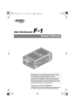
■ R-4 Pro
fig.R-4.eps_50
■ AC adapter
This AC adapter is designed specifically for the R-4 Pro. Do not attempt to use any other adapter with the
R-4.
■ Power Conversion Cable
This is the R-4 Pro dedicated XLR connector (4-pin) and AC adapter conversion cable.
“Connecting the AC adapter and turning the power on/off” (p. 25)
■ USB cable (1 meter)
You can use this cable to connect the R-4 Pro to the USB connector of your computer.
“Connecting to a computer” (p. 82)
* If the AC adapter or USB cable becomes damaged or if you need a replacement for any reason, please contact one of
the Service Centers listed in the “Information” section at the end of this manual.
* Don't remove the ferrite core that's attached to the USB cable.
■ Carrying case
You can use this case to protect the R-4 Pro while it is being transported or stored.
■ Owner’s manual
This is the document you’re reading. Keep it at hand for easy reference.
8
R-4_e_new.book
9 ページ
2006年11月20日 月曜日 午後1時9分
Introducing the R-4 Pro
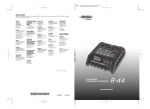
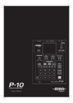
The R-4 Pro’s controls and connectors
Top panel
fig.panel-1.eps_50
1
1
2
3
7
2
4
8
5
6
9
13
10
16
17
11
12
14
1
15
Internal mics [MIC-L, MIC-R]
These are stereo mics built into the R-4 Pro. The audio entering MIC-L is recorded on the 1L channel, while
audio picked up by MIC-R is recorded on the 1R channel. If you’re recording via the internal mics, set the
System Settings menu item Recording Setup to Int-Mic. For details, refer to “Recording from the
internal mics” (p. 33).
* Don’t connect anything to input jacks you’re not using.
2
Internal speakers
These are built-in speakers for monitoring. If you want sound to be heard from the internal speakers, set
the System Settings menu item Speaker to ON. For details, refer to “Playing back” (p. 37).
* No sound will be heard from the internal speakers if you’ve connected headphones to the Headphone jack
( 34 ). Nor will sound be heard from the internal speakers while recording or in recording-standby mode; this
prevents acoustic feedback from occurring.R-4 Pro
3
Power switch [POWER]
This turns the power on/off. To turn the power on or off, press and hold the power switch for about five
seconds. The power switch is lit blue when the power is on.
Don’t turn the power off during recording or playback. Before you turn off the power, you must make sure
that recording or playback is stopped.
* If you accidentally turn off the power during recording, the data that was being recorded will not be stored on the
hard disk.
* The hard disk may be damaged if you turn off the power of the R-4 Pro while data is being read from or written to
the hard disk (such as during recording or playback). You must also be careful not to turn off the power while data
is being transferred between the hard disk and an external memory device.
* Never turn off the power while the R-4 Pro’s display indicates Now Connecting... or Now Processing! Doing so
will cause the R-4 Pro to become unstable and may damage the internal hard disk.
* During recording, pressing the power switch will not turn off the power.
* The hard disk may be damaged if you turn off the power of the R-4 Pro while data on the hard disk is being written
or read, such as during playback or waveform editing.
9
R-4_e_new.book
10 ページ
2006年11月20日 月曜日 午後1時9分
Introducing the R-4 Pro
fig.panel-1.eps_50
1
1
2
3
7
2
4
8
5
6
9
13
10
16
17
11
12
14
4
15
Hold switch [HOLD]
By selecting the HOLD ON position, you can disable the panel buttons so that unwanted operations will
not occur if a button is pressed accidentally.
However, even if this switch is set to HOLD ON, the phantom power switches 5 , limiter switch 6 ,
Input level knobs 25 , and Monitor level knob 26 will still be operable.
5
Phantom power switches [PHANTOM POWER]
These switch the phantom power on/off for the XLR type connectors located on the right panel. Since
separate switches are provided for channels 1/2 and channels 3/4, you can turn phantom power on/off
separately for these channels.
fig.jack-type
* Keep the phantom power turned off for any device other than condenser microphones that require phantom power.
You risk causing damage if you mistakenly supply phantom power to dynamic microphones or other devices that
don’t require such power. Be sure to check the specifications of any microphone you intend to use by referring to the
manual that came with it.
This instrument’s phantom power: 48 V DC, 8 mA Max
(total of all channels must be 25 mA or less)
6
Limiter switch [LIMITER]
This is an on/off switch for an input level limiter in the analog circuitry.
When the input level is too high, the limiter compresses the input level appropriately to prevent distortion.
The limiter can be set to operate each channel independently or use channels 1-2 and 3-4 as pairs (linked).
"Limiter Link" (P.71)
10
R-4_e_new.book
11 ページ
2006年11月20日 月曜日 午後1時9分
Introducing the R-4 Pro
7
Wave edit button [WAVE EDIT]
This button takes you to Wave Edit mode, where you can edit the waveform using operations such as Trim,
Divide, Combine, and Merge. For details, refer to “Editing” (p. 51).
You won't be able to enter Wave Edit mode during playback or recording, or if the R-4 Pro’s hard disk
contains no files that the R-4 Pro can handle.
WAV files are the only type of files that the R-4 Pro can handle.
8
Effect button [EFFECTS]
This button takes you to Effect mode, where you can make effect settings.
For details, refer to “Effects settings” (p. 59).
9
System button [SYSTEM]
This button takes you to a mode where you can make various settings for the R-4 Pro.
For details, refer to “System setup” (p. 64).
10
Marker [MARKER]
Clear button [CLEAR]
This button deletes markers you assigned using the Mark button. Markers are deleted successively, starting
at the marker located immediately before the current location.
button
This button moves you to the marker that is immediately before the current location (the previous marker).
If the current playback location is earlier than the first marker, pressing this button will take you to the
beginning of the project. You will also move to the beginning of the project if no markers have been set.
button
This button moves you to the marker that is immediately after the current location (the next marker).
If the current playback location is at the last marker, pressing this button will take you to the end of the
project. You will also move to the end of the song if no markers have been set.
Mark button [MARK]
By pressing this button you can assign a marker to a desired location in the project file. Markers are
numbered sequentially from the beginning of the project.
11
A-B Repeat button [A-B REPEAT]
This button lets you repeatedly play back the region between two points (A and B) in the project. Simply
assign marker A and marker B while the project is playing, and playback will repeat between markers A
and B.
fig.repeat-a
1. During playback, press the A-B Repeat button once.
That point becomes the beginning (marker A) of repeat playback.
A
fig.repeat-b
2. Press the A-B Repeat button once again. That point will be the end
(marker B) of repeat playback.
A
B
A
B
fig.repeat-ab
The region you specified in steps 1 and 2 will play repeatedly. To cancel repeat
playback, press the A-B Repeat button once again.
12
Display button [DISPLAY]
This button switches the contents of the R-4 Pro’s display.
For details, refer to “Display” (p. 18).
11
R-4_e_new.book
12 ページ
2006年11月20日 月曜日 午後1時9分
Introducing the R-4 Pro
fig.panel-1.eps_50
1
1
2
3
7
2
4
8
5
6
9
13
10
16
17
11
12
14
13
15
Cursor/Monitor Select buttons [CURSOR/MONITOR SELECT]
Use these buttons to select items shown in the display. When you’re in the main screen, you can press the
up/down buttons to select the channel that you want to monitor.
For details, refer to “Display” (p. 18).
14
Exit button [EXIT]
Use this button to return to the previous screen or to cancel an operation.
15
Enter/Finder button [ENTER/FINDER]
Use this button to confirm a setting or set a value. You can also press this when you want to use the Finder
function. For more about the Finder function, refer to “Finder functions” (p. 44).
16
Scrub dial [SCRUB/VALUE]
Use this dial to select a settings item or to modify a value. While stopped or when playback is paused, you
can turn the scrub dial to move the current location forward or backward.
17
Shuttle dial [SHUTTLE]
While the project is playing, turn this dial clockwise to play rapidly forward, or counterclockwise to play
rapidly backward. When the project is stopped, this dial advances the time counter.
12
R-4_e_new.book
13 ページ
2006年11月20日 月曜日 午後1時9分
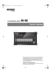
Introducing the R-4 Pro
Front panel
fig.panel-2.eps_50
18
19
20
21
22
23
25
18
24
26
Display
This shows information about the R-4 Pro’s status.
For details, refer to “Display” (p. 18).
19
PREV button [PREV]
Pressing the PREV button while a project is playing or stopped will take you to the beginning of the project
(00:00:00:00F). Pressing this button at the beginning of a project will take you to the preceding project.
You can also press and hold down this button to rewind. This is available both while playing and while
stopped.
* If Play Mode is set to Single in the Player Setup system setting, you can't move to the previous or next
project during playback.
20
NEXT button [NEXT]
Pressing the NEXT button will take you to the next project. You can also press and hold this button to fastforward. This is available both while playing and while stopped.
* If Play Mode is set to Single in the Player Setup system setting, you can't move to the previous or next
project during playback.
21
Stop button [STOP]
This button stops playback or recording. If you press the STOP button during playback, the timer counter
will display the time at which you pressed the STOP button.
22
Pause button [PAUSE]
This button pauses playback or recording.
23
Play button [PLAY]
This button starts playback. The PLAY button is lit blue during playback.
24
Record button [REC]
Recording will begin immediately when you press the REC button. The REC button is lit red during
recording. If you hold down the PAUSE button and press the REC button, the REC button will blink red,
and the R-4 Pro enters recording standby mode. Recording will begin when you then press the REC button
or 22 PAUSE button.
25
Input level knobs 1–4 [INPUT GAIN]/[SENS]
These knobs adjust the input level from each XLR input connectors 1–4 ( 36 ). Input levels of the internal
mics ( 1 ) are adjusted by input level knob 1 (MIC-L) and input level knob 2 (MIC-R).
You can adjust sensitivity to 11 levels: -56, -50, -44, -38, -32, -26, -20, -14, -8, -2, and +4 dBu. You can also set
LEVEL from negative infinity to +8 dB, with the central position at 0 dB.
* When the internal mics are used, sensitivity cannot be adjusted (the knob settings are invalid).
26
Monitor level knob [MONITOR]
This adjusts the output volume from the internal speakers ( 2 ) and the headphone jack ( 37 ).
You can’t adjust the volume from the line output jacks ( 40 ). If you want to adjust the volume of the line
output jacks, adjust the controls of the external speakers or playback system connected to the line output
jacks.
13
R-4_e_new.book
14 ページ
2006年11月20日 月曜日 午後1時9分
Introducing the R-4 Pro
Side panel (left)
32
33
31
30
27
27
28
34
35
29
Power connector [DC IN]
You can connect either the included power conversion cable or a commercially available cable for an
external power device.
28
Digital output connector [DIGITAL OUT]
This connector outputs a digital signal. You can digital devices, such as speakers or mixers, with an XLR
type cable. This connector provides the same audio signal as the headphone jack ( 34 ), but in digital form.
(AES/EBU, IEC 60958-4 compliant)
* Volume cannot be adjusted with the monitor level knob.
29
Digital input connector [DIGITAL IN]
If you want to record a digital signal, connect a XLR type cable to this connector. The digital input signal is
recorded in stereo on channels 1L and 1R. If you want to record in monaural, you’ll need to change the Rec
Mode setting in the System Settings menu. For details, refer to “1 Recording Setup” (p. 72). (AES/EBU,
IEC 60958-4 compliant)
30
USB Storage connector [STORAGE ONLY]
You can connect commercially available USB external memory devices to this connector. You can backup
projects recorded with the R-4 Pro to USB memory or USB hard disks.
For details on external memory devices, see Handling external memory device (p. 79)
31
Timecode Connector [TIMECODE]
You can connect devices with a timecode port. This allows you to records the timecode in the R-4 Pro when
the recording starts (IN) and to output the R-4 Pro internal timecode (OUT). For details on recording the
timecode, see Connecting to a video device with a timecode port (p. 84).
988
32
Security Slot [
]
http://www.kensington.com/
33
USB connector [USB]
You can use the included USB cable to connect the R-4 Pro to your computer to move or copy projects that
were recorded on the R-4 Pro. You can also move or copy files from your computer the R-4 Pro’s hard disk.
14
R-4_e_new.book
15 ページ
2006年11月20日 月曜日 午後1時9分
Introducing the R-4 Pro
34
Headphone jack [PHONES]
You can connect a set of headphones with this jack. Use the monitor level knob ( 26 ) to adjust the
volume. If you connect headphones, no sound is output from the internal speakers ( 2 ).
35
Grounding terminal
927
Depending on the circumstances of a particular setup, you may experience a discomforting sensation, or
perceive that the surface feels gritty to the touch when you touch this device, microphones connected to it,
or the metal portions of other objects, such as guitars. This is due to an infinitesimal electrical charge, which
is absolutely harmless. However, if you are concerned about this, connect the ground terminal (see figure)
with an external ground. When the unit is grounded, a slight hum may occur, depending on the particulars
of your installation. If you are unsure of the connection method, contact the nearest Roland Service Center,
or an authorized Roland distributor, as listed on the “Information” page.
Unsuitable places for connection
• Water pipes (may result in shock or electrocution)
• Gas pipes (may result in fire or explosion)
• Telephone-line ground or lightning rod (may be dangerous in the event of lightning)
15
R-4_e_new.book
16 ページ
2006年11月20日 月曜日 午後1時9分
Introducing the R-4 Pro
Side panel (right)
fig.panel-3.eps_50
37
36
36
XLR input connectors 1–4
These are analog audio input connectors compatible with mic preamps. They accept either balanced or
unbalanced connections.
You can use XLR input connectors 1–4 as four channels of monaural input or as two stereo pairs, 1/2 and
3/4. For details, refer to “1 Recording Setup” (p. 72).
* The XLR type connectors 1-4 can provide 48 V phantom power, allowing you to connect phantom-powered
condenser mics. In this case, turn on the phantom power switch ( 5 ).
fig.XLR-TRS
922
This R-4 pro is equipped with balanced (XLR) type connectors. Wiring diagrams for
these jacks are shown below. Make connections after first checking the wiring
diagrams of other equipment you intend to connect.
37
1:GND
2:HOT
3:COLD
Line output jacks [LINE OUT]
These jacks output an analog audio signal. You can use RCA cables to connect powered speakers, audio
equipment, mixers, and other devices.
The regulated output level is fixed at -10 dBu.
* The volume for each channel during playback can be adjusted on the mixer screen (p. 19).
* Line output can be output as 4-indiv or monitor. See “5 System Setup” in System settings (p. 75) for details.
16
R-4_e_new.book
17 ページ
2006年11月20日 月曜日 午後1時9分
Introducing the R-4 Pro
Bottom panel
38
38
Battery compartment
Install batteries here if you want to operate the R-4 Pro on battery power.
The orientation in which you must insert the batteries is shown on the side of the battery compartment.
Be sure to observe the correct polarity when installing the batteries.
If you’re using the AC adapter, there’s no need to install batteries.
When the R-4 Pro has sufficiently charged batteries, the power source automatically switches between
battery and external power when the external power connector is connected or disconnected.
For details, refer to “Installing batteries and turning on the power” (p. 26).
17
R-4_e_new.book
18 ページ
2006年11月20日 月曜日 午後1時9分
Introducing the R-4 Pro
Display
While playing or stopped
The Main screen
The R-4 Pro Main screen shows information about the project and the operational status of the R-4 Pro.
You can press the [DISPLAY] button to switch the contents of the display.
fig.play-disp.eps
Project name
Progress bar
Total time
Time
counter
Level scale
dBFS
Sampling frequency
Sample size
(bit depth)
Channel
names
Marker indicators
Clip level indicators
Output
assignments
Power source
Date and time
or Timecode
Clip level indicators
Channel level meters
Status indication
Project name
ABS
Time counter
LTC
Progress bar
Total time (LEN: Length)
Level scale
Clip level indicators
Channel level meters
Channel names
Output assignments
Sampling frequency
Sample size
18
Monitor level meters
Displays the name of the project. The file name is shown when you copy WAV
files from your computer via USB to the R-4 Pro’s internal hard disk. File
names containing double-byte characters (e.g., Japanese) are not displayed
correctly, but they can be played.
Displays the time elapsed from the beginning of the project to the current position (absolute time) in hours:minutes:seconds:frames format.
Displays the timecode (p. 84) for the current position in hours: minutes:seconds: frames format.
Displays the current playback location relative to the entire project.
Displays the total time of the entire project.
The sound level for each channel (after adjusting input levels) is shown in real
time.
The markings are relative to 0 dBFS (Full Scale) of the digital signal. For example, 12 indicates -12 dBFS. C is the clipping level (0 dBFS).
Displays up to four channel names. If you’re using one stereo channel, 1L and
1R are shown. If you’re using two stereo channels, 1L, 1R, 2L, and 2R are
shown.
For monaural project, 1, 2, 3, and 4 are shown according to the number of
channels.
When the sensitivity setting is too large and clipping occurs the display is
shown in inverted black and white.
The output assignments show how the audio of each channel is assigned to
the L/R output channels. L means that the audio is output to the left channel,
R to the right channel, and LR to both left and right channels. Channels that
are not shown are not output. From the main screen, you can use the [CURSOR] up/down buttons to select the channel that you want to monitor.
The output is sent to the PHONES jack, line output jacks, and digital output
connector.
* When Output Sel (p. 75) in the system settings is set to "monitor," the
line output jacks output sounds as set in the output assignments.
Displays the sampling frequency and sample size (bit depth) of the currently
selected project.
R-4_e_new.book
19 ページ
2006年11月20日 月曜日 午後1時9分
Introducing the R-4 Pro
Marker display
Monitor level meters
Clip level indicators
Power source
Date and time or timecode
The number on the left is the number of marker located immediately before
the current time counter value. The number on the right indicates the total
number of markers assigned in the currently selected project.
E indicates the end of the current project.
These are the output level meters. The output level assigned to the L/R channels of the monitor is displayed as the final output level after mixing the L and
R channels separately. You can adjust the level of each channel with the channel level sliders from the mixer screen. The level meter is calibrated at -36, -20,
-12, -6, and -3 dBFS from the left.
Displays the power supply source for the R-4 Pro. When power is supplied via
the AC adapter, a power plug icon is shown; when power is supplied via batteries or an external power supply device (see p. 29), a battery icon is displayed.
Displays the current date and time or the timecode.
To change the display, see Connecting to a video device with a timecode port (p. 84)
From the Main screen, you can press the [DISPLAY] button to switch the progress bar area so it shows the
remaining project time (REM: REMAIN).
fig.play-disp2.eps
Remaining time
Remaining time
During playback, this displays the remaining time from the current location
to the end of the project.
The Mixer screen
From the Main screen, press the [DISPLAY] button twice to show to the Mixer screen.
This screen lets you adjust the volume balance for monitoring.
fig.play-disp3.eps
Channel names
Output assignments
Channel level
sliders
Channel level meters
Monitor level meters
Channel level sliders
These levers adjust the playback level for each channel. Use the left/right
[CURSOR/FINDER] buttons to select a slider, and turn the [SCRUB/VALUE]
dial to adjust the value. Each slider can be adjusted within the range 0–120.
The default value is 100.
* The settings are stored by the R-4 Pro and not in the project. When you
turn off the power, the settings revert to the default value.
* These settings do not affect the recording levels.
19
R-4_e_new.book
20 ページ
2006年11月20日 月曜日 午後1時9分
Introducing the R-4 Pro
While recording
The Main screen
The R-4 Pro Main screen displays information about the project and the operational status of the R-4 Pro.
You can press the [DISPLAY] button to switch the contents of the display.
Time counter
Recordable time
Total recording time
ABS
Time counter
LTC
Recordable time
Displays the time elapsed from the beginning of the project to the current position (absolute time) in hours:minutes:seconds:frames format.
Displays the timecode (p. 84) for the current position in hours: minutes:seconds: frames format.
Displays the time that recording can take place.
Displays the total time from the beginning of recording to the current location.
Total recording time
* Even if you record continuously, another new project will be created
automatically when the project reaches 2 GB in size, and recording will
continue. Even for recordings spanning multiple projects, the elapsed time
since you first pressed the [REC] (record) button is shown here.
* For an explanation of the other displays, refer to “While playing or stopped” (p. 18).
From the Main screen, you can press the [DISPLAY] button to change the recordable time display to the
remaining hard disk capacity display.
Remaining hard disk capacity
Remaining hard disk capacity
20
Displays the amount of free memory on the internal hard disk.
R-4_e_new.book
21 ページ
2006年11月20日 月曜日 午後1時9分
Introducing the R-4 Pro
When the [DISPLAY] button is pressed twice while the Main screen is showing, the display changes to
show the recording buffer capacity (BUF: buffer gauge).
Remaining buffuer capacity
The recording buffer is memory that temporarily stores the input sound before it is written to the hard disk.
The buffer gauge indicates how much of the recording buffer has been used. Normally, the recording buffer
never reaches capacity because input sound is immediately written to the hard disk. However, if data
cannot be written to the hard disk or if the hard disk processing capacity decreases and writing data to the
hard disk is delayed due to the R-4 Pro use environment (vibrations or sound pressure), then the data may
accumulate to an excess and the buffer may overflow. (The hard disk processing capacity may be affected
if file arrangement on the disk becomes irregular due to project files being repeatedly written and deleted.)
* When the recording buffer is close to capacity, the “HDD buffering” message is displayed. If vibration or sound
pressure may be the cause, take the R-4 Pro to a location where there is no vibration or sound pressure and check if
the recording buffer capacity is restored.
* When the recording buffer reaches capacity, the buffer gauge moves all the way to the right edge and the “HDD
Slow!” message is shown. Recording does not stop even if the “HDD Slow!” message is displayed, but some sound
is not recorded. This message will not disappear until a button is pressed.
* The same message is displayed if the hard disk processing capacity is diminished and writing to the hard disk is
delayed even in a location where there is no vibration or sound pressure. For important recordings, we recommend
formatting the hard disk before use.
21
R-4_e_new.book
22 ページ
2006年11月20日 月曜日 午後1時9分
Introducing the R-4 Pro
What is a project?
On the R-4 Pro, the data that you record and play back is handled as a project. On the hard disk, each project
actually consists of a folder with one or more files, as shown below.
If you connect the R-4 Pro to your computer, you’ll be able to see how these folders and files are organized.
However, if you change, delete, or rename the files within a project, the R-4 Pro may be unable to play back
that project. Please use caution.
In the system settings, the Recording Setup parameter Rec Mode (p. 73) lets you specify the type of
project you want to record.
Monaural projects
Type
Structure
If there is only one channel, a monaural WAV file will be created with a name consisting of the project name and a.wav extension.
If there are 2–4 channels, a folder will be created with a name consisting of the project
name plus an extension of.pjt. In that folder, monaural WAV files will be created with
names consisting of the channel number and a.wav extension.
MONOx1
MONOx2
MONOx3
MONOx4
fig.project-M1.eps
Project Name
ABC-1.wav
ABC-1.
wav
(MONO)
ABC-2.pjt
1.wav
2.wav
(MONO)
(MONO)
MONOx2
MONOx1
Project Name
ABC-4.pjt
ABC-3.pjt
1.wav
2.wav
3.wav
(MONO)
(MONO)
(MONO)
MONOx3
22
1.wav
2.wav
3.wav
4.wav
(MONO) (MONO) (MONO) (MONO)
MONOx4
R-4_e_new.book
23 ページ
2006年11月20日 月曜日 午後1時9分
Introducing the R-4 Pro
Stereo projects
Type
STEREOx1
STEREOx2
Structure
If there is only one stereo channel pair, a stereo WAV file will be created with a name
consisting of the project name and a.wav extension.
If there are two stereo channel pairs, a folder will be created with a name consisting of
the project name plus an extension of.pjt. In that folder, stereo WAV files will be created with names consisting of the channel number and a.wav extension.
fig.project-S1.eps
Project Name
ABC-2.pjt
ABC-6.pjt
ABC-5.wav
ABC-5
.wav
1.wav
2.wav
(STEREO)
(STEREO)
(STEREO)
STEREOx1
STEREOx2
Four-channel projects
Type
4CH
ABC-7.wav
Structure
A four-channel WAV file will be created with a name consisting of the project name
and a.wav extension.
Project Name
ABC-7.
wav
* If you want to load these files onto your computer, make sure
that your waveform editing software supports four-channel
files.
(4CH)
4CH
Limitations on file size
The R-4 Pro can handle files up to 2 GB in size. If the file size reaches 2 GB during recording, the file is
closed. Then, a new file is created and recording continues. When you finish recording, these files appear
as separate projects.
About BWF
Files created during recording and editing are in BWF (Broadcast Wave Format). BWF files contain
information about the recording time and recording device (EDIROL R-4 Pro) in addition to the data of a
conventional WAV file. Of course, BWF files can be loaded by playback devices or audio editing software
as conventional WAV files.
When the Setup-Mode for “6 Timecode” (p. 66) in the system settings is “OFF,” files are created in WAV
format.
Caution when copying files from your computer
Be aware of the following when copying files from your computer into the R-4 Pro’s internal hard disk.
• The R-4 Pro can only record linear PCM WAV files at sampling frequencies of 44.1, 48, 88.2, 96, or 192 kHz
and bit depths of 16 or 24 bits. It cannot play back any other type of file.
• File and folder names containing double-byte characters (e.g., Japanese) will not be displayed correctly.
• Any files other than WAV files cannot be recognized by the R-4 Pro, and will be ignored.
• Files beginning with “.” (dot) will be ignored.
• You must not copy files larger than 2 GB into the R-4 Pro’s internal hard disk. Doing so will make the R-4
Pro’s operation unstable, and in the worst case might even damage the files in the internal hard disk.
23
R-4_e_new.book
24 ページ
2006年11月20日 月曜日 午後1時9分
Getting ready to use the R-4 Pro
Basic connection examples
921
To prevent malfunction and/or damage to speakers or other devices, always turn down the volume and
turn off the power on all devices before making any connections.
fig.basic.eps
Analog connection
Equipment that has a line input
Amplified speakers/Mixers
Digital connections
Equipment that has a digital input connector
(XLR)
Amplified speakers/Mixers, etc.
AC adaptor
LINE IN
DIGITAL IN
AC outlet
Mic connection
Dynamic mic/Condenser mic
Digital connection
DC IN
LINE OUT
Equipment that has a digital output
DIGITAL OUT
CD player for playback
DIGITAL OUT
DIGITAL IN
Time Code IN/OUT
USB Storage
USB Memmory
USB
Timecode connection
Video camera with a Timecode
connector
PHONES
USB connection
Personal computer with a USB
connector
Headphones
USB
For more about connections, refer to both “Recording” (p. 30) and “Playing back” (p. 37).
926a
When connection cables with resistors are used, the volume level of equipment connected to the inputs XLR
input connector 1 – 4 may be low. If this happens, use connection cables that do not contain resistors.
24
R-4_e_new.book
25 ページ
2006年11月20日 月曜日 午後1時9分
Getting ready to use the R-4 Pro
Connecting the AC adapter and turning the power on/off
* Once the connections have been completed, turn on power to your various devices in the order specified. By turning
on devices in the wrong order, you risk causing malfunction and/or damage to speakers and other devices.
* Reduce the volume before turning on power. Even when the volume is turned down, sound may be produced when
turning on the power. This is not a defect.
* If you connect the AC adapter when batteries are installed, the power will be supplied from the AC adapter.
fig.adapter.eps
Turning on the power
1
Connect the power conversion cable and AC adapter.
* Use only the included AC adapter.
2
Plug the power conversion cable connector into the power connector on the R-4 Pro side panel (left).
3 Plug the AC adapter into an AC power outlet.
4
To turn the power on, press and hold the R-4 Pro [POWER] switch for about two seconds.
Wait until the Main screen appears.
942
* This unit is equipped with a protection circuit. A brief interval (a few seconds) after power up is required before the
unit will operate normally.
Turning off the power
5 From the Main screen, press and hold the R-4 Pro [POWER] switch for about five seconds to turn
the power off.
*923
* If there are batteries in the unit while an AC adaptor is being used, normal operation will continue should the line
voltage be interrupted (power blackout or power cord disconnection).
25
R-4_e_new.book
26 ページ
2006年11月20日 月曜日 午後1時9分
Getting ready to use the R-4 Pro
Installing batteries and turning on the power
■ Types of batteries you can use
• AA alkaline batteries (LR6)
• AA nickel metal-hydride (HR15/51)
(The R-4 Pro cannot recharge nickel metal-hydride batteries. You must use a separate charger.)
* You must specify the type of batteries in the R-4 Pro System Settings menu item “5 System Setup” (p.
75). The R-4 Pro will not operate correctly if the specified battery type that does not match the actual batteries.
1
Make sure that the R-4 Pro is turned off, and disconnect the power
conversion cable from the power connector on the R-4 pro side panel (left).
2 Detach the battery cover from the bottom panel of the
R-4 Pro.
929
* When turning the unit upside-down, handle with care to avoid
dropping it, or allowing it to fall or tip over.
928
* When turning the unit upside-down, get a bunch of newspapers
or magazines, and place them under the four corners or at both
ends to prevent damage to the buttons and controls. Also, you
should try to orient the unit so no buttons or controls get
damaged.
3
Insert eight AA batteries into the battery compartment, making sure to
observe the correct polarity (+ and - symbols).
4 Replace the battery cover.
5
6
Turn on the R-4 Pro.
Press the [SYSTEM] button.
7 Use the [CURSOR] up/down buttons to select 5 System Setup.
8
9
10
11
Press the [ENTER] button.
Using the [SCRUB/VALUE] dial, set the Battery Type to Alkaline if
installing alkaline batteries or to Ni-MH if installing nickel metal-hydride
batteries. The setting is activated as soon as you select it.
When finished with the setting, press the [EXIT] button to return to the
previous screen.
When you have returned to the System Menu screen, press the [EXIT]
button once again.
Although [ENTER] will be blinking in the display, if you do not need to make additional settings, press the
[EXIT] button to return to the Main screen.
26
R-4_e_new.book
27 ページ
2006年11月20日 月曜日 午後1時9分
Getting ready to use the R-4 Pro
■ Caution when using battery power on the R-4 Pro
• If you operate on battery power for an extended time, the batteries will become hot. Be careful not to
burn yourself.
• Please use alkaline batteries, which have a longer life.
• Do not mix new batteries with used batteries nor mix batteries of differing types.
• If you will not be using the R-4 Pro for an extended time, we recommend that you remove the batteries
to prevent leakage or other accidents.
• When using a USB cable to connect the R-4 Pro to your computer, use the AC adapter to prevent the
loss of power while the connection is active.
27
R-4_e_new.book
28 ページ
2006年11月20日 月曜日 午後1時9分
Getting ready to use the R-4 Pro
Battery status
When using the R-4 Pro on battery power, a battery icon is shown in the lower right of the display. As the
battery runs down, the battery icon will change as follows.
Remaining charge
Display
Level 4 (sufficient)
Level 3
Level 2
Level 1
Level 0 (little remaining)
fig.bat-caution.eps
When the battery reaches Level 0, the message in the figure is
shown. Replace the batteries as soon as possible.
If you continue using the R-4 Pro when the batteries are low, the
screen is the figure is shown, and then the power automatically
turns off shortly thereafter.
■ Battery life
(When using alkaline batteries, 44.1 kHz, 16-bit, stereo, with phantom power off)
Continuous playback
Continuous recording
approximately 3.5 hours
approximately 2 hours
* The values for battery life shown above are only approximate; they will vary depending on your system and
conditions of use.
* Battery life is shortened if the display backlighting is left on or if you make heavy use of effects. You can specify how
long the backlight is to remain on with the System settings. For details, refer to “4 LCD Setup” (p. 75).
28
R-4_e_new.book
29 ページ
2006年11月20日 月曜日 午後1時9分
Getting ready to use the R-4 Pro
Using external power sources
When using an external power supply, be sure to set the final voltage.
The final voltage refers to the voltage when voltage can no longer be supplied because the capacity of the
external power source is reduced and voltage decreases as electricity is consumed.
If the final voltage is not properly set for the external power source, the remaining power display is not
shown. See the user's manual for the external power source for the final voltage value.
Furthermore, when the “Battery Low” message is displayed, the recording automatically stops, but the
power does not automatically turn off. Turn the R-4 Pro power off and change the external power source.
* If the final voltage is not set, the “Battery Low” message is not displayed and the power may cut off. Read the
following to set the final voltage for the R-4 Pro.
■ Setting final voltage
ion.eps
1
Press the R-4 Pro [SYSTEM] button.
The display shows the System menu.
ion.eps
2
Use the [CURSOR] buttons to select 5 System Set Up,
and press the [ENTER] button.
The System Setup screen is shown.
ion.eps
3
Use the [CURSOR] buttons to select the Ext-Power item.
ion.eps
4
Use the [SCRUB/VALUE] dial to set the final voltage.
Final voltage values: 9.0/9.5/10.0/10.5/11.0/11.5/12.0 V
* The final voltage value will differ according to the external power
source specifications. Check the specifications for the external power
source being used for details.
5
Press the [EXIT] button twice to return to the Main screen.
This completes setting the final voltage.
29
R-4_e_new.book
30 ページ
2006年11月20日 月曜日 午後1時9分
Recording
Recording from a connected mic
The following describes how to record audio from a mic connected to a R-4 Pro XLR input connector.
fig.mic-1.eps
Turn this ON
if you're using a
condenser mic.
Adjust the input LEVEL
and SENS
● Connections
Connect your mic to a XLR input connector.
Howling could be produced depending on the location of microphones relative to speakers. This can be
remedied by:
1. Changing the orientation of the microphone(s).
2. Relocating microphone(s) at a greater distance from speakers.
3. Lowering volume levels.
● Phantom power switch
Turn this ON when connecting a phantom-powered condenser mic.
fig.input-analog.eps
● System settings
Press the R-4 Pro [SYSTEM] button.
In 1 Recording Setup, set Input Select to Analog.
Set the other items in 1 Recording Setup as appropriate for the
recording you want to make.
* For more about system settings, refer to “System setup” (p. 64).
● Limiter
Turn this ON if you want to prevent unexpectedly loud sounds or strong attacks from producing clipped
noise.
The limiter threshold is -10 dB relative to digital full scale.
The limiter can group and link each channel. See Limiter link (p. 74).
30
R-4_e_new.book
31 ページ
2006年11月20日 月曜日 午後1時9分
Recording
● sensitivity/Input level knobs
These knobs adjust sensitivity/input levels.
When recording in stereo x2, these knobs control the following signals.
Channel 1
Channel 2
Channel 3
Channel 4
STEREO 1 L-channel
STEREO 1 R-channel
STEREO 2 L-channel
STEREO 2 R-channel
SENS/INPUT LEVEL 1 knob
SENS/INPUT LEVEL 2 knob
SENS/INPUT LEVEL 3 knob
SENS/INPUT LEVEL 4 knob
Adjusting the input level
1. Turn the input level knob [SENS] (outer) all the way left.
2. Turn the input level knobs [LEVEL] (inner) to the center position. This signal is 0 dB.
3. Hold down the [PAUSE] button and press the [REC] button.
The R-4 Pro enters recording standby mode. During recording standby, the [REC] button
blinks and the display alternates between REC and STANDBY.
4. Play the sound to be recorded into the microphone.
Gradually turn the input level knob [SENS] toward the right.
sensitivity has 11 steps of -56, -50, -44, -38, -32, -26, -20, -14, -8, -2, and +4 dBu.
* When the channel name display reverses, the input level has reached the clipping level. Set to the knob
to the position just before the display reverses.
5. Adjust the level so that the level meter shown in the
display reaches a point slightly before C (clip level). If
the recording level is too low, quiet sounds will not be
recorded. If the recording level is too high, soft sounds
will be distorted, producing a crackling noise in the
recording.
* If clipping occurs when adjusting SENS, clipping may
occur even if the level meter does not reach the clip level.
The channel name blinks in black and white
level meter (dBFS)
* The level meter displays the clip level (C) as 0 dBFS (FS = full scale).
For example, 12 indicates -12 dBFS.
31
R-4_e_new.book
32 ページ
2006年11月20日 月曜日 午後1時9分
Recording
● Record button [REC]
If you want to begin recording immediately, press the [REC] button.
Recording standby
If you want to put the R-4 Pro in recording standby
mode to be ready to record, hold down the [PAUSE]
button and press the [REC] button.
Recording-standby
The R-4 Pro enters recording standby mode. During recording
standby, the [REC] button blinks and the display alternates
between REC and STANDBY.
When recording is paused, the [REC] button blinks. In
addition, the display alternates between REC and PAUSE.
Press the [REC] or [PAUSE] button during recording standby or
while paused to start recording.
● Other settings
If you want to monitor the sound being recorded, connect headphones to the PHONES jack and use the
monitor level knob to adjust the volume.
Adjusting the monitor level knob does not affect the level of the sound actually being recorded.
To play back the recorded sound, refer to “Playing back” (p. 37).
Caution regarding placement and handling while recording
The internal hard disk is a precision device. If you subject the hard disk to physical shock, such as the
following, you may not be able to access the data on the disk, causing recording or playback to be
unsuccessful. In the worst case, irreparable damage may occur.
Please avoid subjecting the R-4 Pro to strong impact or continuous vibration during use.
The following actions may cause malfunctions
• Subjecting the unit to impact, such as dropping it from a table onto a hard floor.
• Subjecting the unit to continuous vibration, such as by leaving it on an uncushioned surface like
the floor of a moving automobile.
32
R-4_e_new.book
33 ページ
2006年11月20日 月曜日 午後1時9分
Recording
Recording from the internal mics
The following describes how to record an audio source via the R-4 Pro internal mics.
● Phantom power switch
Turn this OFF.
fig.input-intmic.eps
● System settings
Press the R-4 Pro [SYSTEM] button.
In 1 Recording Setup, set Input Select to IntMic.
Set the other items in 1 Recording Setup as appropriate for the
recording you want to make.
* For more about system settings, refer to “System setup” (p. 64).
* The limiter and input level knob [SENS] settings are invalid.
* The internal mics cannot be used if the Rec Freq is set to 192.0 kHz. (They cannot be selected.)
● Input level knobs
Adjust the input level.
1. Hold down the [PAUSE] button and press the [REC] button.
The R-4 Pro enters recording standby mode. During recording standby, the [REC] button
blinks and the display alternates between REC and STANDBY.
2. Play the sound to be recorded into the microphone.
3. Gradually turn the input level knob [LEVEL] toward the right.
4. Adjust the level so that the level meter shown in the
display reaches a point slightly before C (clip level). If
the recording level is too low, quiet sounds will not be
recorded. If the recording level is too high, soft sounds
will be distorted, producing a crackling noise in the
recording.
* If the channel name blinks even before the level meter reaches
C (clip level), the recording level is too high.
level meter (dBFS)
* The level meter displays the clip level (C) as 0 dBFS (FS = full scale). For example, 12 indicates -12
dBFS.
● Record button [REC]
Press the [REC] button to begin recording.
For details on recording standby, refer to “Recording standby” (p. 32).
● Other settings
If you want to monitor the sound being recorded, connect headphones to the PHONES jack and use the
monitor level knob to adjust the volume.
Adjusting the monitor level knob does not affect the level of the sound actually being recorded.
To play back the recorded sound, refer to “Playing back” (p. 37).
33
R-4_e_new.book
34 ページ
2006年11月20日 月曜日 午後1時9分
Recording
Recording digital audio from a digital device
The following describes how to record from a digital device connected to the R-4 Pro digital input
connector.
fig.digital.eps
DIGITAL IN
CD player for playback
DIGITAL OUT
● Connections
Connect your digital device to the digital input connector. You will need a separately available XLR type
cable to connect your device to the R-4 Pro digital input connector.
fig.input-digital.eps
● System settings
1. Press the R-4 Pro [SYSTEM] button.
2. 1 Recording Setup, set Input Select to Digital.
3. Set the sampling frequency to match the input source.
4. Set the other items in 1 Recording Setup as appropriate
for the recording you want to make.
* For more about system settings, refer to “System setup” (p. 64).
* The R-4 Pro is able to synchronize to the clock signal of the digital input connector.
* When the input sampling frequency and set sample size differ, the sampling frequency display blinks and Mute data
is generated.
● Record button [REC]
Press the [REC] button to begin recording.
For details on recording standby, refer to “Recording standby” (p. 32).
● Other settings
If you want to monitor the sound being recorded, connect headphones to the PHONES jack and use the
monitor level knob to adjust the volume.
Adjusting the monitor level knob does not affect the level of the sound actually being recorded.
* When recording digital input, you can not use the input level knob to adjust the input level. The limiter and input
level knobs [SENS] settings are also invalid.
To play back the recorded sound, refer to “Playing back” (p. 37).
34
R-4_e_new.book
35 ページ
2006年11月20日 月曜日 午後1時9分
Recording
Simultaneously recording sound from connected mics
and a digital device
You can record sound from both mics connected to R-4 Pro XLR input connectors 3 and 4 and a digital
device connected to the digital input connector.
Microphone
CD player for playback
DIGITAL OUT
fig.input-analog.eps
● System settings
Press the R-4 Pro [SYSTEM] button.
In 1 Recording Setup, set Input Select to Dig+Ana.
Set the Rec Mode to STEREOx2.
Set the other items in 1 Recording Setup as appropriate for the
recording you want to make.
* For more about system settings, refer to “System setup” (p. 64).
● Input level knobs
Adjust the input level.
Use the following to simultaneously record sound from mics and a digital device.
Channel 1
Channel 2
Channel 3
Channel 4
Digital input L channel
Digital input R channel
Analog input L channel
Analog input R channel
The input level and sensitivity cannot be
adjusted with the input level knob.
Input level, SENS knob 3
Input level, SENS knob 4
See Adjusting the input level (p. 31).
● Record button [REC]
Press the [REC] button to begin recording.
For details on recording standby, refer to “Recording standby” (p. 32).
● Limiter
Turn this OFF when recording an audio source whose levels have already been adjusted (in contrast to a
live audio source whose levels might change unpredictably), or if you have already checked the maximum
volume levels that are going to occur.
Turn this ON if you need to prevent clipping (distortion) that might be caused by unexpectedly loud
volumes or strong attacks.
* The limiter and input level [SENS] knob settings are invalid for digital input.
● Other settings
If you want to monitor the sound being recorded, connect headphones to the PHONES jack and use the
monitor level knob to adjust the volume.
Adjusting the monitor level knob does not affect the level of the sound actually being recorded.
To play back the recorded sound, refer to “Playing back” (p. 37).
35
R-4_e_new.book
36 ページ
2006年11月20日 月曜日 午後1時9分
Recording
Simultaneously recording sound from connected
external mics and the internal mics
You can record sound both from the mics connected to R-4 Pro XLR input connectors 3 and 4 and the
internal mics.
Microphone
fig.input-analog.eps
● System settings
Press the R-4 Pro [SYSTEM] button.
In 1 Recording Setup, set Input Select to Int+Ana.
Set the Rec Mode to STEREOx2.
Set the other items in 1 Recording Setup as appropriate for the
recording you want to make.
* The internal mics cannot be used if the Rec Freq is set to 192 kHz.
If Rec Freq is set to 192 kHz after setting Int+Ana, the settings
automatically change to Dig+Ana.
* For more about system settings, refer to “System setup” (p. 64).
● Input level knobs
Adjust the input level.
Use the following to simultaneously record sound from internal mics and external mics.
Channel 1
Channel 2
Channel 3
Channel 4
Internal mic L channel
Internal mic R channel
Analog input L channel
Analog input R channel
Input level knob 1
Input level knob 2
Input level, SENS knob 3
Input level, SENS knob 4
* The input level knob [SENS] settings are invalid for the internal mics.
See Adjusting the input level (p. 31).
● Record button [REC]
Press the [REC] (record) button to begin recording.
For details on recording standby, refer to “Recording standby” (p. 32).
● Other settings
If you want to monitor the sound being recorded, connect headphones to the PHONES jack and use the
monitor level knob to adjust the volume.
Adjusting the monitor level knob does affect the level of the sound actually being recorded.
To play back the recorded sound, refer to “Playing back” (p. 37).
36
R-4_e_new.book
37 ページ
2006年11月20日 月曜日 午後1時9分
Playing back
This section explains how to play back audio recorded on the R-4 Pro and projects on the R-4 Pro internal
hard disk. Make the correct settings and connections before playing anything back.
• Connections before playback.............................. (p. 37)
• Setup before playback........................................... (p. 39)
• Playing back ............................................................. (p. 41)
Connections before playback
Connecting headphones
Headphones are a convenient way to monitor while recording or to check sound immediately after
recording.
1. Turn the [MONITOR] level knob all the way to the left to minimize the volume.
2. Connect your headphones to the PHONES jack.
3. Slowly turn the [MONITOR] level knob toward the right to adjust the volume.
Connecting amplified speakers
The following describes how to connect amplified speakers that have line input jacks or a digital input jack.
1. Switch off the power to the R-4 Pro.
2. Minimize the volume of the speakers you want to connect, and then turn off the power.
3. Depending on the type of speakers you are using, connect the amplified speakers to the R-4 Pro
[LINE OUT] line output jacks or [DIGITAL OUT] digital output connector.
4. Switch on the R-4 Pro power.
5. Switch on your speakers, and gradually increase the volume to the desired level.
* You cannot adjust the volume of the audio output from the R-4 Pro line output jacks.
Connecting a mixer or other analog device
(analog connection: line output jacks)
The following describes how to connect a mixer or other audio device that has line input jacks.
1. Switch off the power to the R-4 Pro.
2. Minimize the volume of the mixer or other device being connected.
3. Connect the mixer to the R-4 Pro [LINE OUT] line output jacks.
You will need separately available audio cables (not included) to connect to the R-4 Pro line output jacks.
* Line output can be output as 4-indiv or monitor. See “System Setting" in “5 System Setup” (p. 75) for details.
4. Switch on the R-4 Pro power.
5. Switch on your mixer, and gradually increase the volume to the desired level.
* You cannot adjust the volume of the audio output from the R-4 Pro line output jacks.
37
R-4_e_new.book
38 ページ
2006年11月20日 月曜日 午後1時9分
Playing back
Connecting a device having a digital input port
(digital connection: R-4 Pro digital output connector)
The following describes how to connect devices with digital input ports, such as mixers, speakers, or
recording devices.
fig.basic-disp.eps
The sampling frequency of the project playing back will be the
sampling frequency of the audio output from the digital output
connector.
1. Switch off the power to the R-4 Pro.
2. Turn off power to the device with the digital input port.
3. Connect the R-4 Pro digital output connector [DIGITAL OUT] to the digital
input connector of the device with digital input.
* You will need a separately available XLR type cable (not included) to connect your digital device to the R-4 Pro digital
output connector.
4. Switch on the R-4 Pro power.
5. Turn on power to the device with the digital input port.
* You cannot adjust the volume of the R-4 Pro digital audio signal.
38
R-4_e_new.book
39 ページ
2006年11月20日 月曜日 午後1時9分
Playing back
Setup before playback
Player Setup
fig.recording-1.eps
1 Press the R-4 Pro [SYSTEM] button.
The system menu screen appears in the display.
fig.player-setup2.eps
2
Use the [CURSOR] buttons to choose 2 Player Setup, and
press the [ENTER] button.
The Player Setup screen appears.
3 Use the [SCRUB/VALUE] dial to choose the Play Mode
value.
* The setting is applied as soon as you select it. You do not need to press the [ENTER] button.
You can also setup the following items.
Menu
Play Mode
Player Setup
settings
Single
Sequential
Repeat
OFF, ON
Playback method
Selects the playback mode.
Only the selected project will play.
The projects in the folder containing the currently selected project will
play consecutively.
Selects whether playback will repeat.
If Play Mode is Single, only that project will be repeated. If it is Sequential, the projects in the folder containing the currently selected
project play consecutively, and then the projects in the same folder
will be repeated consecutively from the beginning.
* The values in boldface are the default values.
* For more about system settings, refer to “System setup” (p. 64).
39
R-4_e_new.book
40 ページ
2006年11月20日 月曜日 午後1時9分
Playing back
Speaker
You can use the R-4 Pro internal speakers to monitor the sound without having to connect headphones or
other equipment.
fig.recording-1.eps
1
Press the R-4 Pro [SYSTEM] button.
The system menu screen appears in the display.
fig.speaker-on.eps
2
Use the [CURSOR] buttons to choose 3 Speaker, and
press the [ENTER] button.
The Speaker screen appears.
Speaker Switch setting
ON
OFF
Output destination
Internal speakers
Line output jacks
Digital output jack
Line output jacks
Digital output jack
* The values in boldface are the default values.
* You cannot monitor with the internal speakers while recording. You will need to monitor through headphones. Note
that sound will not be output from the internal speakers if headphones are connected. If you want to use the internal
speakers, you must disconnect the headphones.
* For more about system settings, refer to “System setup” (p. 64).
40
R-4_e_new.book
41 ページ
2006年11月20日 月曜日 午後1時9分
Playing back
Playing back
Normal playback
After performing the steps described in “Connections before playback” (p. 37) and “Setup before
playback” (p. 39), proceed as follows.
1
Select the project that you want to play.
From the Main screen, press the [ENTER/FINDER] button. In the Finder screen that appears, use the
[CURSOR] up/down buttons and the [SCRUB] dial to select a project. For more about the Finder
screen, refer to “Finder functions” (p. 44).
Alternatively, you can use the [PREV] button or [NEXT] button on the front panel to select the project
you want to play. The projects are in alphabetical order.
2
Press the [PLAY] button.
The selected project will play.
3
Slowly raise the [MONITOR] level knob to the desired volume for listening.
* Projects with names beginning with “.” are ignored, and will not be shown.
* Projects whose filename extension is not .pjt or .wav will be ignored and will not be shown.
41
R-4_e_new.book
42 ページ
2006年11月20日 月曜日 午後1時9分
Playing back
Markers
You can assign markers at desired locations in a project. Then you can use the
button to move backward or forward to a marker location.
You can use the Mark function either while playing or while recording.
1
button or
Use the [NEXT] button or the [SHUTTLE] dial to find the location at which
you want to assign a marker.
Play, fast-forward, or rewind the project to the location at which you want to assign a marker.
fig.mark-1.eps
2
Press the [MARK] button at the location at which
you want to assign a marker.
You can assign markers while playing, recording, or
stopped.
The display indicates the number of markers as shown in
the figure at right. Marks are numbered sequentially
starting from the beginning of the project.
You can assign up to 99 markers.
Repeat steps 1 and 2 to assign markers as desired.
3
Number of markers
in the project
Marker information
Number of markers
you’ve passed
After assigning one or more markers, proceed as follows.
You can use these operations either while playing or while stopped.
button
Moves to the marker immediately before the current location (previous marker).
button
Moves to the marker immediately following the current location (next marker).
CLEAR button
Deletes the marker that you set with the [Mark] button. Markers are deleted consecutively, starting with
the marker immediately before the current location.
42
R-4_e_new.book
43 ページ
2006年11月20日 月曜日 午後1時9分
Playing back
Repeat playback (A-B REPEAT)
You can repeatedly play back between two points (A-B) in the project. Simply assign points A and B during
playback, and the playback will repeat between points A and B.
fig.repeat-a
1
Play the project.
During playback, press the [A-B REPEAT] button once. The [A-B REPEAT]
button blinks, and that location becomes the starting point (A) for repeat
playback.
A
* If you press the STOP button after assigning point A but before assigning point B,
point A will be deleted.
fig.repeat-b
2
Press the [A-B REPEAT] button once again. The [A-B REPEAT]
button stays lit, and that location becomes the end point (B) for
repeat playback.
A
B
A
B
fig.repeat-ab
Playback automatically repeats between the points you specified in steps 1
and 2.
To cancel repeat playback, press the [A-B REPEAT] button when points A and
B have already been assigned. The [A-B REPEAT] button goes out, and repeat
playback is cancelled.
Please note
* If you press the STOP button after assigning point A but before assigning point B, point A will be deleted.
* If the song plays all the way to the end after assigning point A, playback will repeat between point A and the end
of the song.
* If you press the [STOP] button during repeat playback, playback stops and the repeat region (A-B) settings are
cleared.
43
R-4_e_new.book
44 ページ
2006年11月20日 月曜日 午後1時9分
Finder functions
The R-4 Pro saves projects as files on its internal hard disk. You can use the Finder functions to select a
project from numerous folders or projects within folders, to delete an unwanted project, or to copy a project
to an external memory device.
Finder functions
No.
1
2
3
4
5
6
Menu
Select
Delete
Rename
Copy
Move
Make Folder
Operation
Select and load a project.
Delete a project.
Rename a project.
Copy the selected project.
Move the selected project to a different folder.
Create a new folder.
See
p. 44
p. 45
p. 46
p. 47
p. 48
p. 49
Selecting a project (Select)
fig.finder-1.eps
1
With project playback stopped and the Main screen (p. 18)
shown on the display, press the [ENTER/FINDER]
button. The Finder screen shown in the figure is
displayed.
Projects are shown in descending alphabetical order.
HD represents the R-4 Pro hard disk, and EX represents an
external memory device such as USB memory connected to the USB storage connector.
fig.finder-select.eps
2
In the Finder screen, use the [CURSOR] up/down
buttons or the [SCRUB] dial to select the desired project.
Then press the [ENTER] button.
If the desired project is in a folder, the hard disk (HD), or the external memory device (EX), you
can press the [CURSOR] right button to move into the selected folder (i.e., move to a lowerlevel folder).
If you want to move back to the upper-level folder, press the [CURSOR] left button.
fig.finder-select2.eps
3
When the screen at right is displayed, use the [CURSOR]
buttons to select 1 Select.
The project is selected, and you are returned to the Main screen.
Alternatively, with a project selected (step 2), you can press the
[PLAY] button (instead of pressing the [ENTER] button) to play
the selected project. You are returned to the Main screen when
playback begins.
* Since you cannot directly play back projects from the external memory device, you cannot select them. You will have
to copy the desired project to the R-4 Pro internal hard disk before you can select it.
44
R-4_e_new.book
45 ページ
2006年11月20日 月曜日 午後1時9分
Finder functions
Deleting a project (Delete)
fig.finder-1.eps
1 While the Main screen is shown on the display, press the
[ENTER/FINDER] button. The Finder screen shown in
the figure is displayed.
Projects are shown in descending alphabetical order.
fig.finder-select.eps
2
In the Finder screen, use the [CURSOR] up/down
buttons or the [SCRUB] dial to select the project you
want to delete. Then press the [ENTER] button.
If the desired project is in a folder, the hard disk (HD), or the external memory device (EX), you
can press the [CURSOR] right button to move into the selected folder (i.e., move to a lowerlevel folder). If you want to move back to the upper-level folder, press the [CURSOR] left
button.
fig.finder-cf.eps
* If you want to select the external memory device, select the hard disk
(HD) and then press the [CURSOR] left button to show the external
memory device (EX). However, if the external memory device is not
mounted, it will not be displayed. See Connection and removal
(p. 79)
* Press the [CURSOR] right button after selecting EX to reference
the external memory device contents.
fig.finder-delete1.eps
3
When the screen shown in the figure is displayed, use the
[CURSOR] buttons to select 2 Delete.
fig.finder-delete2.eps
4
The screen shown in the figure is displayed. Press the
[ENTER] button to execute the Delete operation.
* If you decide to cancel without executing, press the [EXIT] button
before you press the [ENTER] button.
fig.finder-delete3.eps
Do not turn off the power while a project is being deleted.
45
R-4_e_new.book
46 ページ
2006年11月20日 月曜日 午後1時9分
Finder functions
Renaming a project (Rename)
fig.finder-1.eps
1
While the Main screen is shown in the display, press the
[ENTER/FINDER] button. The Finder screen shown in
the figure is displayed.
Projects are shown in descending alphabetical order.
fig.finder-select.eps
2
In the Finder screen, use the [CURSOR] up/down
buttons or the [SCRUB] dial to select the project you
want to rename. Then press the [ENTER] button.
If the desired project is in a folder, the hard disk (HD), or the external memory device (EX), you
can press the [CURSOR] right button to move into the selected folder (i.e., move to a lowerlevel folder). If you want to move back to the upper-level folder, press the [CURSOR] left
button.
fig.finder-cf.eps
* If you want to select the external memory device, select the hard disk
(HD) and then press the [CURSOR] left button to show the
external memory device (EX). However, if the external memory device
is not mounted, it will not be displayed. See Connection and
removal (p. 79)
* Press the [CURSOR] right button after selecting EX to reference
the external memory device contents.
fig.finder-rename1.eps
3 When the screen shown in the figure is displayed, use the
[CURSOR] buttons to choose 3 Rename.
fig.finder-rename2.eps
4 Use the [CURSOR] left/right buttons to move the
cursor through the characters of the project name or folder
name shown in the display. Place the cursor on the
character that you want to change, and then use the
[CURSOR] up/down buttons or the [SCRUB/VALUE]
dial to change the character.
Use the [CLEAR] button to delete a character and the [Mark] button to insert a character. Use these
buttons to edit the name as desired.
When finished editing the name, press the [ENTER] button.
* If you decide to cancel without renaming, press the [EXIT] button before you press the [ENTER] button.
fig.finder-rename3.eps
Do not turn off the power while a project is being renamed.
46
R-4_e_new.book
47 ページ
2006年11月20日 月曜日 午後1時9分
Finder functions
Copying a project (Copy)
fig.finder-1.eps
1 While the Main screen is shown in the display, press the
[ENTER/FINDER] button. The Finder screen shown in
the figure is displayed.
Projects are shown in descending alphabetical order.
fig.finder-select.eps
2
In the Finder screen, use the [CURSOR] up/down
buttons or the [SCRUB] dial to select the copy source
project (the project you want to copy). Then press the
[ENTER] button.
If the desired project is in a folder, the hard disk (HD), or the external memory device (EX), you
can press the [CURSOR] right button to move into the selected folder (i.e., move to a lowerlevel folder).
If you want to move back to the upper-level folder, press the [CURSOR] left button.
fig.finder-cf.eps
* If you want to select the external memory device, select the hard disk
(HD) and then press the [CURSOR] left button to show the
external memory device (EX). However, if the external memory device
is not mounted, it will not be displayed. See Connection and
removal (p. 79)
* Press the [CURSOR] right button after selecting EX to reference
the external memory device contents.
fig.finder-copy1.eps
3
When the screen shown in the figure is displayed, use the
[CURSOR] buttons to select 4 Copy.
fig.finder-copy2.eps
4
Use the [CURSOR] up/down buttons or the [SCRUB/
VALUE] dial to select the copy destination folder (the
folder to which you want to copy the project). Then press
the [ENTER] button to execute the Copy operation. You
can also select HD (hard disk) or EX (external memory
device) as the copy destination,.
* If you decide to cancel without copying, press the [EXIT] button.
fig.finder-copy3.eps
Do not turn off the power while a project is being copied.
* If the copy destination contains an identically named project, a number
such as -1 or -2 is appended to the name of the copied project.
47
R-4_e_new.book
48 ページ
2006年11月20日 月曜日 午後1時9分
Finder functions
Moving a project (Move)
* You cannot move a project between the hard disk and an external memory device. If you need to do this, you can
first copy the project, and then delete the copy source project.
fig.finder-1.eps
1
While the Main screen is shown in the display, press the
[ENTER/FINDER] button. The Finder screen shown in
the figure is displayed.
Projects are shown in descending alphabetical order.
fig.finder-select.eps
2
In the Finder screen, use the [CURSOR] up/down
buttons or the [SCRUB] dial to select the project that you
want to move. Then press the [ENTER] button.
If the desired project is in a folder, the hard disk (HD), or the external memory device (EX), you
can press the [CURSOR] right button to move into the selected folder (i.e., move to a lowerlevel folder).
If you want to move back to the upper-level folder, press the [CURSOR] left button.
fig.finder-cf.eps
* If you want to select the external memory device, select the hard disk
(HD) and then press the [CURSOR] left button to show the
external memory device (EX). However, if the external memory device
is not mounted, it will not be displayed. See Connection and
removal (p. 79)
* Press the [CURSOR] right button after selecting EX to reference the
external memory device contents.
fig.finder-move1.eps
3 When the screen shown in the figure is displayed, use the
[CURSOR] buttons to select 5 Move.
fig.finder-move2.eps
4
Use the [CURSOR] up/down buttons or the [SCRUB/
VALUE] dial to select the destination folder (the folder to
which you want to move the project). Then press the
[ENTER] button to execute the Move operation. You can
also select HD (hard disk) as the destination.
* If you decide to cancel without moving, press the [EXIT] button.
fig.finder-move3.eps
Do not turn off the power while a project is being moved.
48
R-4_e_new.book
49 ページ
2006年11月20日 月曜日 午後1時9分
Finder functions
Creating a new folder (Make Folder)
fig.finder-1.eps
1 While the Main screen is shown in the display, press the
[ENTER/FINDER] button. The Finder screen shown in
the illustration will appear.
Projects are shown in descending alphabetical order.
fig.finder-make1.eps
2
In the Finder screen, use the [CURSOR] up/down
buttons or the [SCRUB] dial to select HD (hard disk)
located at the top level.
Then press the [ENTER] button.
If the desired project is in a folder, the hard disk (HD), or the external memory device (EX), you
can press the [CURSOR] right button to move into the selected folder (i.e., move to a lowerlevel folder).
If you want to move back to the upper-level folder, press the [CURSOR] left button.
fig.finder-cf.eps
* If you want to select the external memory device, select the hard disk
(HD) and then press the [CURSOR] left button to show the
external memory device (EX). However, if the external memory device
is not mounted, it will not be displayed. See Connection and
removal (p. 79)
* Press the [CURSOR] right button after selecting EX to reference the
external memory device contents.
fig.finder-make2.eps
3 When the screen shown in the figure is displayed, use the
[CURSOR] buttons to select 2 Make Folder.
fig.finder-make3.eps
4 When the screen shown in the figure is displayed, press
the [ENTER] button to confirm the operation.
fig.finder-make4.eps
Do not turn off the power while a folder is being created.
49
R-4_e_new.book
50 ページ
2006年11月20日 月曜日 午後1時9分
Finder functions
fig.new-folder.eps
5 A folder named NewFolder is created.
Projects are shown in alphabetical order, and folders are shown in
alphabetical order after the projects.
Use the [CURSOR] up/down or the [SCRUB] dial to verify that
the new folder was created.
If an identically named folder already exists, a number will be
added to the name of the newly created folder, e.g., NewFolder-1,
NewFolder-11, NewFolder-111, etc.
50
R-4_e_new.book
51 ページ
2006年11月20日 月曜日 午後1時9分
Editing
You can edit the projects that you have recorded with the R-4 Pro directly on the R-4 Pro.
1
Editing
command
Trim
2
Divide
3
Combine
4
Merge
No.
Operation
See
Creates a new project from a region extracted between two specified
points in a waveform.
Creates two new projects by dividing the project at a specified point in a
waveform.
Appends a project to the end of the currently selected project. The two
files are joined to create a single new file.
Merges a project consisting of multiple files into a single channel.
p. 51
p. 53
p. 55
p. 57
* Executing any of these editing commands leaves the original project file unchanged.
* There is no Undo function.
Editing procedure
Trim
This command extracts the region between the two points you specify in the waveform and creates a new
project from the extracted region.
Playback, stop, scrub dial, shuttle dial, and marker operations may be performed even while using this
command. However, operations related to A-B Repeat cannot be performed.
fig.wave-1.eps
1 Press the R-4 Pro [WAVE EDIT] button. The Wave Edit
Menu screen is shown in the display.
2
Use the [CURSOR] buttons to select 1 Trim, and press the
[ENTER] button.
fig.wave-2.eps
The editing screen shown at the right is displayed.
Waveform level
zoom
Time axis zoom
Time axis zoom (1/1–1/65536)
Adjust with the [CURSOR] left/right buttons
Elapsed
time
Total time
Waveform level zoom (x1–x64)
Adjust with the [CURSOR] up/down buttons
1
* If you decide not to adjust the settings, press the [EXIT] button.
fig.wave-3.eps
3
While playing or fast-forwarding, press the [ENTER]
button when you reach the beginning (point 1 ) of the
region you want to extract.
Alternatively, you can use the scrub dial or shuttle dial to specify
the point instead of doing so during playback.
fig.wave-trim1.eps
* The value of point [ 1 ] is displayed as a location in the sample (data).
1
Project
51
R-4_e_new.book
52 ページ
2006年11月20日 月曜日 午後1時9分
Editing
fig.wave-4.eps
4 In the same way, move to the end (point
) of the region
you want to extract, and press the [ENTER] button.
2
* The value of point 2 is displayed as a location in the sample (data).
2
fig.wave-trim2.eps
1
2
Project
fig.wave-5.eps
5 A screen asking you to confirm the specified points is
shown.
fig.wave-6.eps
If you are satisfied with the points you specified, press the
[ENTER] button to confirm the settings. If you decide to try again,
you can press the [EXIT] button once and re-specify the end of the
region (point 2 ). You can then press the [EXIT] button once
again and re-specify the beginning of the region (point 1 ).
Even when the screen shown at the right is displayed, you can
cancel the process by pressing the [EXIT] button.
* Do not turn off the power while a project is being saved or while a
process is running.
fig.wave-trim2.eps
6 The extracted region is saved as a
new project with the same name as
the original project but with “-1”
appended to it. The original project
remains unchanged.
For example, if the original project is
named Project, the new project is named
Project-1.
1
2
Project
1
Project
2
Project-1
fig.media-full.eps
If the internal hard disk does not have enough space to save the project, a
“Media Full!” message is shown.
52
R-4_e_new.book
53 ページ
2006年11月20日 月曜日 午後1時9分
Editing
Divide
This command divides a project at the point you specify in the waveform. Two new projects are created.
Playback, stop, scrub dial, shuttle dial, and marker operations may be performed even while using this
command. However, you cannot perform A-B Repeat operations.
fig.wave2-1.eps
1 Press the R-4 Pro [WAVE EDIT] button. The Wave Edit
Menu screen is shown in the display.
2
Use the [CURSOR] buttons to select 2 Divide, and press
the [ENTER] button.
The editing screen shown at the right is displayed.
fig.wave2-2.eps
Time axis zoom (1/1–1/65536)
Adjust with the [CURSOR] left/right buttons.
Time axis zoom
Waveform level zoom (x1–x64)
Adjust with the [CURSOR] up/down buttons.
* If you decide not to adjust the settings, press the [EXIT] button.
Waveform level
zoom
Elapsed
time
Total time
Specified
point
fig.wave2-3.eps
3
While playing or fast-forwarding, press the [ENTER]
button when you reach the point at which you want to
divide the project.
Alternatively, you can use the scrub dial or shuttle dial to specify
the point instead of doing so during playback.
fig.wave2-4.eps
4
A screen asking you to confirm the specified point will
appear.
fig.wave2-5.eps
If you are satisfied with the point you specified, press the [ENTER]
button to confirm the settings. If you decide to cancel Divide,
press the [EXIT] button.
Even when the screen shown at the right is displayed, you can
cancel the process by pressing the [EXIT] button.
* Do not turn off the power while a project is being saved or while a process is running.
* It may take some time to save the project if it contains a large amount of data.
53
R-4_e_new.book
54 ページ
2006年11月20日 月曜日 午後1時9分
Editing
fig.wave-divide.eps
5 The divided project is saved as two new
projects with the same name as the original
project but with
“-1” and “-2” appended to the names. The
original project remains unchanged.
For example, if the original project is named Project,
the new projects is named Project-1 and Project-2.
Project
Project
Project-1
fig.media-full.eps
If the internal hard disk does not have enough space to save the project, a
“Media Full!” message is shown.
54
Project-2
R-4_e_new.book
55 ページ
2006年11月20日 月曜日 午後1時9分
Editing
Combine
This command appends another project (of the same format) onto the end of the currently selected project.
The two files are joined to create a single new file.
You cannot perform playback, stop, or operate the scrub dial or shuttle dial while using this command.
1
Select the project (the “base project”) to which you want to append another
project.
In the Main screen, use the [NEXT] button or [PREV] button to select the desired project. Alternatively,
you can use the cursor buttons in the Finder screen.
fig.wave3-1.eps
2
3
Press the R-4 Pro [WAVE EDIT] button. The display
shows the Wave Edit Menu screen.
Use the [CURSOR] buttons to select 3 Combine, and
press the [ENTER] button.
fig.wave3-2.eps
The display shows an editing screen like the one at right.
Base project
* If you decide to cancel the operation, press the [EXIT] button.
Project
to append
fig.wave3-3.eps
4
Use the [CURSOR] buttons to select the project that you
want to append, and press the [ENTER] button.
fig.wave3-4.eps
If you decide to cancel the operation, press the [EXIT] button.
Even when the screen shown at the right is displayed, you can
cancel the process by pressing the [EXIT] button.
* Do not turn off the power while a project is being saved or while a
process is running.
* It may take some time to save the project if it contains a large amount
of data.
The “base project” and the “project to be appended” must have the same sampling frequency,
sample size (bit depth), and number of channels.
fig.wave3-error.eps
If you select a project that cannot be appended, a “Improper Proj.“
message is shown.
55
R-4_e_new.book
56 ページ
2006年11月20日 月曜日 午後1時9分
Editing
fig.wave-combine.eps
5 The combined projects are saved as a new project
Project-1
Project-2
with the same name as the original project but with
“-1” appended to it. The original project remains
unchanged.
For example, if the original project is named Project, the
new project is named Project-1.
Project
fig.media-full.eps
If the internal hard disk does not have enough space to save the project, a
“Media Full!” message is shown.
56
R-4_e_new.book
57 ページ
2006年11月20日 月曜日 午後1時9分
Editing
Merge
If the currently selected project consists of multiple files (MONO x2, MONO x3, MONO x4, STEREO x2),
this command merges them into a single channel.
How Rec Mode will change
Before Merge
MONOx2
MONOx3
MONOx4
STEREOx2
After Merge
MONOx1
STEREOx1
* Since MONO x1, STEREO x1, or 4 ch. projects cannot be merged, the Merge command does not appear in the
menu when selecting these projects.
fig.merge-1.eps
1
Press the R-4 Pro [WAVE EDIT] button. The Wave Edit
Menu screen is shown.
2 Use the [CURSOR] buttons to select 4 Merge, and press
the [ENTER] button.
fig.merge-2.eps
The editing screen shown at right is displayed.
If you want to adjust the level (Mix Level) of the channels in the
project, you can do so. Use the [CURSOR] up/down buttons or
the [SCRUB] dial to specify the value.
For example, in a stereo two-channel project (STEREO x2), you
might set the Mix Level to -6.0 dB so that the level of each channel
will be lowered by 6 dB when they are merged.
* If you decide to cancel the settings, press the [EXIT] button.
fig.merge-3.eps
3
If you are satisfied with the settings, press the [ENTER]
button to confirm.
If you decide not to cancel Merge, press the [EXIT] button.
Even when the screen shown at the right is displayed, you can
cancel the process by pressing the [EXIT] button.
* Do not turn off the power while a project is being saved or while a process is running.
* It may take some time to save the project if it contains a large amount of data.
fig.media-full.eps
If the internal hard disk does not have enough space to save the project, a
“Media Full!” message is shown.
57
R-4_e_new.book
58 ページ
2006年11月20日 月曜日 午後1時9分
Editing
Edit Timecode
This command changes the timecode for the data recorded in BWF format.
* The Edit Timecode screen does not display for non-BWF formatted data.
fig.merge-1.eps
1
Press the R-4 Pro [WAVE EDIT] button. The Wave Edit
Menu screen is shown.
2 Use the [CURSOR] buttons to select Edit Timecode, and
press the [ENTER] button.
A edit screen as shown in the figure is displayed.
fig.merge-2.eps
3
Use the [CURSOR] button to select the input location,
and then set the timecode with the [SCRUB/VALUE]
dial.
* H:M:S:F: indicates Hours: Minutes: Seconds: Frames, respectively.
The F value differs according to the Frame Rate value in the timecode
Setup.
* To cancel the settings, press the [EXIT] button.
fig.merge-3.eps
merge-3.eps
4 If you are satisfied with the settings, press the [ENTER]
button to confirm.
* Do not turn off the power while a project is being saved or while a
process is running.
* It may take some time to save the project if it contains a large amount
of data.
58
R-4_e_new.book
59 ページ
2006年11月20日 月曜日 午後1時9分
Effects settings
The R-4 provides five types of effects. You can apply an effect to the incoming sound as it is being recorded,
or you can apply an effect to the playback. You can also change the effect settings for each channel.
* Effects are not available when the R-4 Pro is operating at 96 kHz.
Effect types provided on the R-4 Pro
No.
Effect name
0
No Effect
1
2
3-Band EQ
Graphic EQ
3
Noise Gate
4
Enhancer
5
Comp&DeEsser
6
MS-Mic
Effect
No effects are applied.
Use this setting if you want to preserve the effect on/off setting of each
channel but do not want an effect to be applied.
This is a three-band equalizer.
You can adjust the gain of six fixed-frequency bands.
This effect minimizes the noise that might be heard in silent regions as
well as low-frequency noise.
By adding a phase-shifted sound to the direct sound, this effect sharpens
the definition of the sound and pushes it toward the foreground.
This cuts the sibilance that can be obtrusive in a vocal, making the sound
smoother. It also reduces the difference between loud and soft sounds,
making the level more consistent.
A compressor evens out the level differences between loud and soft
sounds.
A de-esser reduces the unpleasant sibilance (exaggerated “s” sound) that
is sometimes present in a vocal.
Converting sound recorded on a MS (Mid-Side type) mic to stereo.
If you apply an effect while recording, the volume and tone of the recorded sound will be different than the
original sound.
Before applying an effect aggressively during recording, it is a good idea to monitor the sound through
headphones in recording standby mode to make sure that the sound is not clipped or distorted. It is also a
good idea to make a test recording beforehand with those settings.
For details on the procedure, refer to “Effects settings” (p. 59).
If the [EFFECT] button is pressed during recording or playback, the effect is toggled on/off. To prevent
unintentionally switching an effect on or off, we recommend turning the HOLD switch on.
What is an effect?
On the R-4 Pro, an “effect” is a process that digitally transforms the sound, giving it greater clarity or
impact.
Effects can also make the sound more intelligible or reduce undesirable noise.
What is clipping?
Applying an effect or boosting the level may increase the sound level (volume) beyond the maximum that
a device can handle; this occurrence is called clipping. Loud sounds may be accompanied by distortion or
crackly noises.
The MS mic
The MS mic creates stereo sound by combining sound from a main mic that records central sounds (midsignal: M) and a bi-directional mic that records lateral sounds (side signal: S).
59
R-4_e_new.book
60 ページ
2006年11月20日 月曜日 午後1時9分
Effects settings
Applying effects
You can adjust the R-4 Pro effects not only while standing-by for recording or playback, but also while you
listen to the sound during actual playback or recording.
This section explains how to adjust the effect settings while playing back or in recording standby mode.
fig.effect-set.eps
1
3
6
2
fig.effect-1.eps
1
Press the R-4 Pro [EFFECTS] button.
The Effects setup screen is shown in the display.
fig.effect-type.eps
2
Use the [SCRUB/VALUE] dial to select the desired effect
type.
For details on each effect type, see to “Effects” (p. 62).
fig.effect-link.eps
3 Press the [CURSOR] down button. The cursor will
move to the “Link” field.
CH1 CH2 CH3 CH4
CH1+2 CH3+4
CH1+2+3+4
60
The effect on/off setting and effect parameters are set independently for each
channel.
The effect on/off setting and effect parameters are linked for channels 1 and
2 and for channels 3 and 4.
Choose this setting if the project uses channels 1 and 2 and channels 3 and 4
as stereo pairs.
The effect on/off setting and effect parameters are linked for all channels.
R-4_e_new.book
61 ページ
2006年11月20日 月曜日 午後1時9分
Effects settings
fig.effect-link2.eps
4 Use the [SCRUB/VALUE] dial to specify the channels to
be linked.
fig.effect-play2.eps
5
In the same way, set the “PLAY” and “REC” fields.
PLAY
OFF
ON
The effect are not applied during playback
The effect are applied during playback
fig.effect-rec.eps
REC
OFF
ON
The effect are not applied during recording
The effect are applied during recording
fig.effect-para.eps
6
Press the [DISPLAY] button.
The effect parameter screen is shown on the display.
* The effect parameter screen does not appear when 0: No Effect is
selected as the type.
7
Use the [CURSOR] buttons and the [SCRUB/VALUE]
dial to set each effect parameter.
fig.effect-para2.eps
8
If you selected “CH1 CH2 CH3 CH4” or “CH1+2 CH3+4” in
the “Link” field, press the [DISPLAY] button.
The next channel (or pair of channels) will appear in the display.
While setting effect parameters, you can return to the previous screen by pressing the [EXIT]
button. The effect settings you make are stored until you change them. However, if you change
the effect type (Type), the settings you made are reset to the default values.
9
When finished setting the effect parameters, press the [EXIT] button to return to the Main screen.
Each effect has various parameters that you can adjust to alter the character of the effect. The settings you
make are stored even when the R-4 Pro power is switched off. However, if you change the effect type, these
settings are reset to the default values.
61
R-4_e_new.book
62 ページ
2006年11月20日 月曜日 午後1時9分
Effects settings
Effects
1: 3-Band EQ
No.
1
Parameter
name
Range of values
Default
values
Explanation
MID-F
200Hz, 250Hz, 315Hz,
400Hz, 500Hz, 630Hz,
800Hz, 1kHz, 1.25Hz,
1.6kHz, 2kHz, 2.5kHz,
3.15kHz, 4kHz, 5kHz,
6.3kHz
1kHz
Specifies the center frequency of the
mid-range equalizer.
2
MID-Q
0.5, 1.0, 2.0, 4.0, 8.0
2.0
3
LOW
-12dB–0dB–+12dB
0dB
4
MID
-12dB–0dB–+12dB
0dB
5
HIGH
-12dB–0dB–+12dB
0dB
6
LEVEL
0 - 120
100
Sets the range of the region centered
on the Mid Freq for which the gain
will change. Higher Q settings narrow the region in which the change
occurs.
Adjusts the gain of the low-range
equalizer.
Adjusts the gain of the mid-range
equalizer.
Adjusts the gain of the high-range
equalizer.
Adjusts the overall volume.
2: Graphic EQ
No.
1
2
3
4
5
6
7
Parameter
name
125Hz
250Hz
500Hz
1kHz
2kHz
4kHz
Level
Range of values
-12dB–0dB–+12dB
-12dB–0dB–+12dB
-12dB–0dB–+12dB
-12dB–0dB–+12dB
-12dB–0dB–+12dB
-12dB–0dB–+12dB
0–120
Default
values
0dB
0dB
0dB
0dB
0dB
0dB
100
Explanation
Adjusts the gain at 125 Hz.
Adjusts the gain at 250 Hz.
Adjusts the gain at 500 Hz.
Adjusts the gain at 1 kHz.
Adjusts the gain at 2 kHz.
Adjusts the gain at 4 kHz.
Adjusts the overall volume.
3: Noise Gate
Parameter
name
Range of values
Default
values
Explanation
1
LO-CUT
OFF, 40Hz, 55Hz, 63Hz,
80Hz, 100Hz, 125Hz, 160Hz,
200Hz, 250Hz, 315Hz,
400Hz, 500Hz, 630Hz,
800Hz, 1kHz
100Hz
Cuts unwanted low-frequency noise
such as wind.
2
THRESHOLD
OFF,1–100
20
3
LEVEL
0–120
100
No.
62
Specifies the volume threshold below which the sound will be cut.
Adjusts the overall volume.
R-4_e_new.book
63 ページ
2006年11月20日 月曜日 午後1時9分
Effects settings
4: Enhancer
No.
Parameter
name
Range of values
Default
values
1
SENSE
0–100
50
2
MIX
0–100
50
3
LEVEL
0–120
100
Explanation
Adjusts the sensitivity of the enhancer effect.
Adjusts the amount of phase-shifted
sound that is to be mixed with the input.
Adjusts the overall volume.
5: Comp&DeEsser
No.
Parameter
name
Range of values
Default
values
1
DE-ESSER
OFF, ON
ON
2
THRESHOLD
0–100
50
3
RATIO
1.0:1, 1.2:1, 1.5:1, 2.0:1, 2.8:1,
4.0:1, 8.0:1, 16.0:1, Inf:1
4.0:1
4
ATTACK
0.25–100ms
10ms
5
RELEASE
50–5000ms
100ms
6
GAIN
7
LEVEL
-6.0dB–+18.0dB
(The value will change in
steps of 0.5dB)
0–120
Explanation
Turn this ON to reduce unpleasant
sibilance.
Sets the volume (threshold level) at
which the compressor begins to operate. Compression is applied to the
input when it exceeds this level.
Lower threshold settings mean that
the compressor is applied even at
lower levels.
Adjusts the ratio at which the sound
is compressed when the input exceeds the threshold level. Higher ratios mean that the sound is
compressed more strongly.
Adjusts the time over which the
amount of compression specified by
Ratio is reached once compression is
triggered when the input exceeds the
threshold level. Higher Attack settings mean that compression is applied more slowly.
Adjusts the time until compression is
released once the input falls below
the threshold level. Higher Release
settings mean that the sound reverts
to its uncompressed state more slowly.
0.0dB
Adjusts the gain following compression.
100
Adjusts the overall volume.
6: MS-Mic
No.
1
2
Parameter
name
Wide
Level
Range of values
0–100
0–120
Default
values
80
100
Explanation
Adjusts sound dispersion.
Adjusts the overall volume.
* You can adjust the stereo dispersion during recording or playback. This case is limited to MS mics that can directly
output the mid and side signals. Connect the mid-signal to CH1 (CH3) and the side signal to CH2 (CH4).
63
R-4_e_new.book
64 ページ
2006年11月20日 月曜日 午後1時9分
System setup
You can make settings related to the R-4 Pro system when performing initial settings for recording or
playback. Press the R-4 Pro [SYSTEM] button to enter the system setup menu. See “Example
operations” (p. 65) for setup procedures.
64
No.
1
2
3
4
5
6
Menu item
Recording Setup
Player Setup
Speaker
LCD Setup
System Setup
Timecode
7
Date & Time
8
Project Name
9
HDD Utility
10
USB Utility
11
Factory Reset
Summary
Allows you to make recording settings.
Allows you to make playback settings.
Turns the speaker on/off.
Allows you to make display settings.
Allows you to make settings to specify how the R-4 Pro operates.
Allows you to make settings to specify how the Timecode operates.
Allows you to set the date and time of the R-4 Pro internal calendar.
You can specify the year, month, and date (day).
The R-4 Pro automatically assigns a name to project files that are created when recording. You can set how this name will be assigned.
Allows you to perform utility operations on the R-4 Pro internal hard
disk.
Allows you to perform utility operations on the external memory device connected to the R-4 Pro.
Restores the R-4 Pro to the factory default settings.
See
p. 65
p. 65
p. 65
p. 65
p. 65
p. 67
p. 67
p. 68
p. 69
p. 69
p. 71
R-4_e_new.book
65 ページ
2006年11月20日 月曜日 午後1時9分
System setup
Example operations
Recording Setup settings
You can use the same procedure to make the settings listed below. As an example, we will show how to
make Recording Setup settings.
Recording Setup
Player Setup
Speaker
LCD Setup
System Setup
fig.recording-1.eps
1
Press the R-4 Pro [SYSTEM] button.
The System Menu screen is shown in the display.
fig.recording-2.eps
2
Use the [CURSOR] buttons to choose 1 Recording Setup,
and press the [ENTER] button.
The Recording Setup screen is shown.
3
Use the [SCRUB/VALUE] dial to choose the Input Select
value.
The setting is applied as soon as you select it.
You do not need to press the [ENTER] button.
fig.recording-3.eps
4
Use the [CURSOR] buttons to select Rec Freq.
5 Use the [SCRUB/VALUE] dial to select the Rec Freq.
value.
6
7
In the same way, use the [CURSOR] buttons and the
[SCRUB/VALUE] dial to select and set the remaining
items.
When finished making settings, press the [EXIT] button.
You are returned to the System Menu screen.
8
Press the [EXIT] button once again to return to the Main screen.
If you want to make other system settings, use the [CURSOR] buttons to select the desired menu item.
65
R-4_e_new.book
66 ページ
2006年11月20日 月曜日 午後1時9分
System setup
Timecode settings
fig.recording-1.eps
1
Press the R-4 Pro [SYSTEM] button.
The System Menu screen is shown in the display.
fig.recording-2.eps
2
Use the [CURSOR] buttons to select 6 Timecode, and
press the [ENTER] button.
The Recording Setup screen is shown.
fig.recording-2.eps
3
Use the [CURSOR] buttons to select 1 Setup, and press
the [ENTER] button.
The Recording Setup screen is shown.
fig.recording-3.eps
4 Use the [SCRUB/VALUE] dial to select the Mode value.
The setting is applied as soon as you select it.
You do not need to press the [ENTER] button.
fig.recording-3.eps
5
Use the [CURSOR] buttons to select the Frame Rate.
6 Use the [SCRUB/VALUE] dial to select the Frame Rate value.
7
In the same way, use the [CURSOR] buttons and the [SCRUB/VALUE] dial to choose and set the
remaining items.
8 When finished making settings, press the [EXIT] button twice.
You are returned to the System Menu screen.
9 Press the [EXIT] button once again to return to the Main screen.
If you want to make other system related settings, use the [CURSOR] buttons to select the desired menu item.
* Please set Pre Recording to OFF when recording using timecode. If Pre Recording is set, then the timecode will not
match.
* If the [PAUSE] button is pressed during recording, the timecode will not match during playback. Please exercise
caution.
66
R-4_e_new.book
67 ページ
2006年11月20日 月曜日 午後1時9分
System setup
Date & Time settings
fig.recording-1.eps
1
Press the R-4 Pro [SYSTEM] button.
The System Menu screen is shown in the display.
fig.data-1.eps
2
Use the [CURSOR] buttons to select 7 Date & Time, and
press the [ENTER] button.
The Date & Time screen is shown.
fig.data-2.eps
3
Use the [CURSOR] buttons and the [SCRUB/VALUE]
dial to set the date and time.
When finished making settings, press the [EXIT] button.
You are returned to the System Menu screen.
* If you decide to cancel, press the [EXIT] button.
4 Press the [EXIT] button once again to return to the Main
screen.
If you want to make other system related settings, use the [CURSOR] buttons to select the desired menu item.
67
R-4_e_new.book
68 ページ
2006年11月20日 月曜日 午後1時9分
System setup
Project Name settings
fig.pj-name1.eps
1
Press the R-4 Pro [SYSTEM] button.
The System Menu screen is shown in the display.
fig.pj-name2.eps
2
Use the [CURSOR] buttons to select 8 Project Name, and
press the [ENTER] button.
The Project Name screen is shown.
fig.pj-name3.eps
3
Use the [CURSOR] buttons to select the name you want
to edit, and press the [ENTER] button.
A screen for editing the project name is shown.
4
Use the [CURSOR] buttons, [SCRUB/VALUE] dial,
[CLEAR] button, and [MARK] button to edit the name.
When finished, press the [ENTER] button.
You are returned to the Project Name screen.
* If you decide to cancel, press the [EXIT] button.
Available characters
(space) !#$%&'()+,-.01234546789;=@
ABCDEFGHIJKLMNOPQRSTUVWXYZ[]^_` abcdefghijklmnopqrstuvwxyz{}
5 Press the [EXIT] button once again to return to the Main screen.
If you want to make other system related settings, use the [CURSOR] buttons to select the desired menu item.
68
R-4_e_new.book
69 ページ
2006年11月20日 月曜日 午後1時9分
System setup
Using the HDD Utility
fig.hd-uti1.eps
1
Press the R-4 Pro [SYSTEM] button.
The System Menu screen is shown in the display.
fig.hd-uti2.eps
2
Use the [CURSOR] buttons to select 9 HDD Utility, and
press the [ENTER] button.
The HDD Utility screen is shown.
* If you decide to cancel, press the [EXIT] button.
format
3 Use the [CURSOR] buttons to select either “Format” or
“Check,” and press the [ENTER] button.
fig.hd-uti3.eps
4
The display displays the “Are you sure?” confirmation
message. Use the [CURSOR] buttons to select “Yes” if
you are sure you want to execute or “No” if you decide to
cancel without executing.
Then press the [ENTER] button.
fig.hd-uti4.eps
The message shown at right is shown during processing.
Do not turn off the power during processing.
When processing has completed, you will automatically return to
the System Menu screen.
5
Press the [EXIT] button once again to return to the Main
screen.
If you want to make other system related settings, use the [CURSOR] buttons to select the desired menu item.
69
R-4_e_new.book
70 ページ
2006年11月20日 月曜日 午後1時9分
System setup
Using the USB Storage Utility
fig.hd-uti1.eps
1
Press the R-4 Pro [SYSTEM] button.
The System Menu screen is shown in the display.
fig.hd-uti2.eps
2
Use the [CURSOR] buttons to select 10 USB Storage
Utility, and press the [ENTER] button.
When the connection to an external memory device is not
mounted, the USB Storage Utility starts as shown in the
figure to the right.
* A connected external memory device cannot not be loaded if it is not
mounted.
format
hd-uti2.eps
When the connection to an external memory device is mounted,
the USB Storage Utility starts as shown in the figure to the right.
* If you decide to cancel, press the [EXIT] button.
format
fig.NO-CF.eps
* If no external memory device is inserted, the message shown at right is
shown.
3
Select one of the following with the [CURSOR] button and
select by pressing the [ENTER] button.
when not mounted
when mounted
Moun
Unmount
Format
Format
Check
fig.hd-uti3.eps
4
The display displays the “Are you sure?” confirmation
message. Use the [CURSOR] buttons to select “Yes” if
you are sure you want to execute or “No” if you decide to
cancel without executing.
Then press the [ENTER] button.
fig.hd-uti4.eps
The message shown at right is shown during processing.
Do not turn off the power during processing.
When processing has completed, you will automatically return to
the System Menu screen.
5
Press the [EXIT] button once again to return to the Main
screen.
If you want to make other system related settings, use the [CURSOR] buttons to select the desired menu item.
70
R-4_e_new.book
71 ページ
2006年11月20日 月曜日 午後1時9分
System setup
Executing Factory Reset (Restoring the factory default settings)
fig.Fact-uti1.eps
1
Press the R-4 Pro [SYSTEM] button.
The System Menu screen is shown in the display.
fig.fact-reset.eps
2
Use the [CURSOR] buttons to select 11 Factory Reset,
and press the [ENTER] button.
The Factory Reset screen is shown.
3 Press the [ENTER] button if to perform Factory Reset.
* If you decide to cancel, press the [EXIT] button.
fig.fact-reset2.eps
4
The display displays the “Are you sure?” confirmation
message. Use the [CURSOR] buttons to select “Yes” if
you are sure you want to execute or “No” if you decide to
cancel without executing.
Then press the [ENTER] button.
When processing has completed, you will automatically return to
the System Menu screen.
5
Press the [EXIT] button once again to return to the main screen.
If you want to make other system related settings, use the [CURSOR] buttons to select the desired menu
item.
71
R-4_e_new.book
72 ページ
2006年11月20日 月曜日 午後1時9分
System setup
System Menu
1 Recording Setup
The values in boldface are the default values.
* You cannot make Recording Setup settings during recording or playback.
Menu item
Value
Analog
Digital
Input Select
Dig + Ana
IntMic
Int + Ana
72
Rec Freq.
44.1 kHz,
448.0 kHz,
88.2kHz
96 kHz
192kHz
Rec Bit
16 bit,
24 bit
Function
This selects the type of input.
Choose this setting if you want to record analog input. Connect your mic or analog audio device to the XLR input connectors. With this setting, any input from
the internal mics or the digital input jack is ignored.
Choose this setting if you want to record digital input. The signal from a digital
device connected to the digital input connector is recorded. With this setting,
any input from the internal mics or the XLR input connectors is ignored.
The sampling frequency is specified by the Rec Freq. setting, and the bit depth
by the Rec Bit setting.
Choose this setting if you want to simultaneously record digital and analog input. The signal from the digital device connected to the digital input connector
and the signal from the mic or analog audio device connected to the XLR input
connectors are recorded simultaneously. For these settings, the digital input is
on channels 1 and 2. Use channels 3 and 4 for the analog input. This cannot be
selected when the Rec Freq is 192 kHz. This setting cannot be selected when the
Rec Freq is set to 192 kHz.
Choose this setting if you want to record via the internal mics. LIMITER and sensitivity are invalid. This setting cannot be selected when the Rec Freq is set to 192
kHz.
Choose this setting if you want to simultaneously record from the internal mics
and analog input. MIC-L is on channel 1, and MIC-R is on channel 2. Use channels 3 and 4 for the analog input. LIMITER and sensitivity are invalid. This setting cannot be selected when the Rec Freq is set to 192 kHz.
This sets the sampling frequency for recording.
Higher sampling frequencies allow higher-quality recording but produce larger
project files, meaning that there will be less available recording time on the hard
disk.
The 44.1 kHz setting is sufficient when recording audio that falls within the normally audible range. This frequency is also the most suitable to use if you are going to load the recorded file into your computer and create a music CD from it.
You can use the higher frequency settings when recording audio that contains a
significant amount of high-frequency content, from instruments such as cymbals, or when you want to capture the brightness and transparency of a natural
environment.
This sets the sample size (bit depth) for recording. A larger sample size allows
the sound to be captured in greater detail but produces a larger project file,
meaning that there will be less available recording time on the hard disk.
Use the 16-bit setting for normal recording. This setting allows the broadest
compatibility when loading the recorded file into your computer for playback.
Use the 24-bit setting if you want to capture the tonal character and ambience in
greater detail, such as when recording an instrumental or vocal performance.
R-4_e_new.book
73 ページ
2006年11月20日 月曜日 午後1時9分
System setup
Menu item
Value
Function
One-channel recording to
one monaural file
Two-channel recording to
two monaural files
Three-channel recording to
three monaural files
MONOx1
MONOx2
MONOx3
Four-channel recording to
four monaural files
MONOx4
STEREOx1
Two-channel recording to
one stereo file
STEREOx2
Four-channel recording to
two stereo files
Rec Mode
4CHx1
Four-channel recording to
one four-channel file
This selects the structure of the project file that is
created during recording. A monaural WAV file
will be created for each channel. Choose these
settings if you are using a separate mic for the vocal and performance or each speaker in a conversation, so that a separate file is created for each
channel. These settings create monaural WAV
files. If Input Select is set to Analog, you can create up to four monaural files. If Input Select is set
to IntMic or Digital, you can create up to two
monaural files.
* You cannot select MONO x3, MONO x4, or
STEREO x2 if Input Select is set to IntMic or
Digital.
* You cannot select MONO x3 or MONO x4 if
Rec Freq. is set to 88.2kHz, 96 kHz, or
192kHz.
Two channels are recorded as L and R to create a
stereo WAV file.
If Input Select is set to Analog, one stereo WAV
file with channel 1 as L and channel 2 as R is created. The inputs to channels 3 and 4 are ignored.
If Input Select is set to IntMic or Digital, one stereo WAV file is created.
If Input Select is set to Analog, a stereo file with
channel 1 as L and channel 2 as R is created, and
another stereo file with channel 3 as L and channel 4 as R is also created.
* When Input Select is set to either IntMic or
Digital or when Rec Freq. is set to 192 kHz,
STEREO x 2 cannot be selected.
Channels 1–4 will be recorded as a single WAV
file. Be aware that not all computer software can
handle four-channel WAV files.
* When Input Select is set to either IntMic or
Digital or when Rec Freq. is set to 192 kHz,
4CH x 1 cannot be selected.
MONOx1 MONOx2 MONOx3 MONOx4 STEREOx1 STEREOx2
4CHx1
44.1kHz
48kHz
88.2kHz
96kHz
192kHz
* Cannot be used if Input Select is set to IntMic or Digital.
73
R-4_e_new.book
74 ページ
2006年11月20日 月曜日 午後1時9分
System setup
Menu item
Pre Recording
Value
OFF, 1–29
sec
Function
You can specify the length of time that the sound is captured “retroactively,”
starting from before the moment you pressed the [REC] (record) button. This
setting specifies the number of seconds that is captured retroactively.
* The maximum time depends on the sampling frequency, the sample size (bit
depth), and the mode setting.
Rec Freq.
Rec Bit
Rec Mode
44.1
44.1
48
48
48
48
88.2
88.2
96
96
192
16
16
16
16
24
24
24
24
24
24
24
STEREO x1
STEREO x2
STEREO x1
STEREO x2
STEREO x1
STEREO x2
STEREO x1
STEREO x2
STEREO x1
STEREO x2
STEREO x1
Pre Recording
29
14
27
13
18
9
9
4
8
4
4
* The R-4 Pro consumes power even during pre-recording. If you are running on
batteries, you should pay attention to the remaining battery charge.
Project Name
Date,
Name1–8
1/2/3/4
1+2/3+4
Limiter link
1+2+3+4
1+2/3/4
1/2/3+4
74
* Please set Pre Recording to OFF when recording using timecode. If Pre Recording
is set, then the timecode will not match.
This specifies how names are assigned to the recorded project files. You can select to base the name on the date and time or on the Project Name that you set.
If you choose Date, a project recorded at 3:45 and 12 seconds in the morning January 2, 2005, is given the name of “050102034512”.
If you use the Date setting, the name of the project indicates the time that it was
recorded; this is convenient when you have recorded a large number of projects
and are looking for a specific one.
If you choose Name, the project name is the name you set in “8 Project
Name” (p. 77) plus an ascending serial number. If you specify a clearly identifiable project name, e.g., SCENE001, SCENE002, etc. the project files are grouped
together.
If you use the Name1–8 setting, the project name is the name you set in “8
Project Name” (p. 77) plus an ascending serial number. The serial number is
incremented automatically, e.g., R4_Scene1_001–R4_Scene1_999, up to 999.
The R-4 Pro uses the number of the highest serial numbered project name in the
current folder as the start value for the serial number.
The limiter is applied independently to each channel.
The limiter for channels 1 and 2 is linked. In addition, the limiter for channels 3
and 4 is linked.
The limiter for all channels is coupled.
The limiter for channels 1 and 2 is linked. The limiter for channels 3 and 4 is applied independently.
The limiter for channels 3 and 4 is linked. The limiter for channels 1 and 2 is applied independently.
R-4_e_new.book
75 ページ
2006年11月20日 月曜日 午後1時9分
System setup
2 Player Setup
Parameter
Value
Single
Play Mode
Repeat
Sequential
OFF, ON
Function
This selects the playback mode.
Only the selected project will play.
All projects in the folder containing the currently selected project are played sequentially.
This selects whether playback will repeat.
If Play Mode is set to Single, only that project is played repeatedly. If Play
Mode is set to Sequential, the projects in the folder containing the currently selected project play to the end of the list, and then the projects in that same folder
play sequentially again from the beginning of the list.
3 Speaker
Parameter
Value
Speaker
Switch
OFF, ON
Function
This switches the internal speakers on/off.
* Even if this is set to on, no sound is produced by the internal speakers during
recording standby or recording if the Recording Setup parameter Input Select
is set to IntMic; the speakers also remain silent while headphones are being used.
4 LCD Setup
Parameter
Value
Contrast
1–5–10
BackLight
OFF, 1–10
BackLight
Timer
OFF, 2 sec,
5 sec, 10 sec,
20 sec
Function
This adjusts the LCD contrast. Higher settings emphasize the white areas of the
display.
This adjusts the brightness of the LCD backlight.
The OFF setting turns the backlight off.
Higher settings make the backlight brighter and consume more power. If you
are operating the R-4 Pro on battery power, pay attention to the remaining
amount of battery capacity.
Sets the amount of time until the display backlight turns off when no operations
have been performed on the R-4 Pro.
If you are operating the R-4 Pro on battery power, use this setting to conserve
battery life.
5 System Setup
Parameter
Value
Battery
Time
Alkaline,
Ni-MH
Ext-Power
Adapter,
9.0/9.5/
10.0/10.5/
11.0/11.5/
12.0V
Output Sel
4-indiv
monitor
Function
Sets the type of batteries you are using.
Choose the Alkaline setting if you are using alkaline batteries, or Ni-MH if you
are using nickel metal-hydride batteries.
* If you choose a setting that does not match the type of batteries that are actually
installed, the remaining battery power indication will be incorrect.
Sets the final voltage when using an external power source. The "Battery Low!"
message is displayed when the voltage of the external power source drops below the set voltage.
Sets the sound output type.
The sound from each channel from LINE OUT is output without modification.
Sound is output according to the output assignments
75
R-4_e_new.book
76 ページ
2006年11月20日 月曜日 午後1時9分
System setup
6 Timecode
Menu item
Parameter
Value
OFF
INT
Mode
EXT
REC-RUN
Setup
RTC
Frame Rate
24, 25, 29.97, 29.97D, 30, 30D
Out Select
ON, OFF
Chase
ON, OFF
MANUAL
(H: M: S: F)
Set Int TC
JAM EXT
(H: M: S: F)
Set Rec-Run
TC
TARGET
H : 00–23
M : 00–59
S : 00–59
F : 00–23/24/29
(According to the Frame Rate setting)
H : 00–23
M : 00–59
S : 00–59
F : 00–23/24/29
(According to the Frame Rate setting)
H : 00–23
M : 00–59
S : 00–59
F : 00–23/24/29
(According to the Frame Rate setting)
Function
The timecode is not recorded.
The R-4 Pro timecode is used. The timecode
operates normally.
Uses the timecode sent from the connected
device.
The R-4 Pro timecode is used. The timecode
only runs during recording.
The internal clock is used in place of the timecode.
Selects the frame rate.
Selects whether to output the timecode to the
timecode connector.
Plays the project in the R-4 Pro that matches
the timecode input from the timecode connector.
Sets the start time for the timecode when
Mode is set to INT.
* CURRENT is the current timecode.
When Mode is set to EXT, the start time for
the timecode can be set to match the external
device
* CURRENT is the current timecode.
When Mode is set to REC-RUN, the start time
for the timecode can be set.
7 Date & Time
fig.date-1a.eps
You can set the date and time.
Year
Month
Date (Weekday)
If Project Name is set to Date, the time you specify here is
used to set the date in the project name.
This setting is also used for the date and time shown in the
Main screen.
Time
76
R-4_e_new.book
77 ページ
2006年11月20日 月曜日 午後1時9分
System setup
8 Project Name
You can use Name 1–8 to specify eight different name types. The project name will consist of this name
plus a consecutive number of 001, 002, 003, ... appended to it. For example, in the case of the default setting
R4_Scene1, the project name will be R4_Scene1_001.
In order to use a name you have specified here, you will need to set the Recording Setup parameter
Project Name to Name 1–8.
Available characters
(space) !#$%&'()+,-.01234546789;=@
ABCDEFGHIJKLMNOPQRSTUVWXYZ[]^_` abcdefghijklmnopqrstuvwxyz{}
9 HDD Utility
You can use utility commands on the R-4 Pro internal hard disk. You cannot execute HDD Utility
commands during recording or playback.
Command
Format
Explanation
Formats the internal hard disk.
All projects and folders in the internal hard disk are erased; afterwards, the hard disk is
empty.
* Be sure to back up your projects before you execute this command.
Checks the internal hard disk, and after reorganization, frees up any hard disk space not
used by R-4 Pro Projects.
Check
Scan
* There is no guarantee that this command will restore the internal hard disk to a normal
operating state. Since this command directly manipulates the hard disk sectors, projects
may be damaged. Be sure to back up your projects before executing this command.
This checks all sectors of the internal hard disk to see whether they are readable.
This check takes approximately 50 minutes to perform.
If no problems are found, you are returned to the System Menu. If a problem is found,
the indication “HDD failure” is shown. Please back up your data, then contact your dealer or a Roland Service Center for service. In such situations, please be aware that we cannot make any guarantees regarding recovery of any content that may be lost from the
hard disk.
77
R-4_e_new.book
78 ページ
2006年11月20日 月曜日 午後1時9分
System setup
10 USB Storage Utility
You can perform utility commands on a external memory device connected to the R-4 Pro. You can not
execute USB Storage Utility commands during recording or playback.
When not mounted
Command
Mount
Format
Explanation
Mounts an external memory device after it is connected.
* The external memory device is not recognized if it is not mounted, even if it is connected.
Formats the external memory device. All projects and folders on the external memory
device are erased; afterwards, the external memory device is empty.
* Be sure to back up your projects before you execute this command.
* The external memory device is automatically mounted after formatting completes.
When mounted
Command
Explanation
Unmounts the external memory device so it can be disconnected.
Unmount
* If you disconnect an external memory device before unmounting it, the data may be
damaged. Please exercise caution.
Formats the external memory device. All projects and folders on the external memory
device is erased; afterwards, the external memory device is empty.
Format
* Be sure to back up your projects before you execute this command.
Checks the external memory device, and after reorganization, frees up any space on the
external memory device not used by R-4 Pro Projects.
Check
* There is no guarantee that this command will restore the external memory device to a
normal operating state. Since this command directly manipulates the sectors on the
external memory device, projects may be damaged. Be sure to back up your projects before
you execute this command.
11 Factory Reset
This command resets the following settings to their factory default settings. You can not execute Factory
Reset during recording or playback.
Recording Setup
Player Setup
Speaker
LCD Setup
System Setup
Project Name
HDD Utility
Effects (Type, Link, Play, Rec, Parameters)
Timecode
78
R-4_e_new.book
79 ページ
2006年11月20日 月曜日 午後1時9分
Appendix
Handling external memory device
An external memory device can be used to move project files on the R-4 Pro hard disk to a computer or to
move WAV files from a computer to the R-4 Pro hard disk. See Finder functions (p. 44) for details on how
to handle these files.
* A USB cable can also be used to connect directly to a computer to exchange files. For details see Connecting to
a computer (p. 82).
* Recordings cannot be made directly to an external memory device, and files cannot be played from an external
memory device.
* External memory devices refer to USB memory, external HDD, or memory read from a memory card reader.
Connecting an external memory device
• Non-memory devices are not recognized.
• When the memory device, such as a hard disk, is partitioned, only the first partition is recognized.
• When multiple media are inserted in a multimedia card reader, only one card is recognized. Which
media is recognized depends on the card reader specifications.
Connection and removal
fig.memory.eps
With the surface of the
external memory device
facing upward, insert it
all the way into
the connector
Connection
1
You can connect External memory devices to the USB Storage [STORAGE
ONLY] port.
Be sure to insert the external memory device plug all the way in.
If you forcibly insert the plug incorrectly, the R-4 Pro unit or external memory device may be damaged.
Please exercise caution.
fig.usb-1.eps
2
Mount the external memory device following the
procedure below.
* When connecting an external memory device, it will not load if it is
not mounted.
1. Press the [SYSTEM] button on the R-4 Pro.
The display shows the System Menu screen.
79
R-4_e_new.book
80 ページ
2006年11月20日 月曜日 午後1時9分
Appendix
fig.usb-mount.eps
2. Use the [CURSOR] button to select 10 USB Storage
Utility, and press the [ENTER] button.
When the connection to an external memory device is not
mounted, the USB Storage Utility starts as shown in the
figure to the right.
* To cancel, press the [EXIT] button.
fig.No-Connect.eps
* When an external memory device is not connected, a message as
shown in the figure is displayed.
3. Use the [CURSOR] button to select [Mount], and press the
[ENTER] button.
fig.usb-yes.eps
4. “Are you sure?” is displayed. Use the [CURSOR] button to
select “Yes” to execute or “No” to cancel.
Once the selection is made, press the [ENTER] button.
fig.usb-Now.eps
The process is displayed as shown.
Do not turn off power during execution.
When the process completes, the display automatically
returns to the System Menu screen.
* Return to the main screen by pressing the [EXIT] button
again.
Removal
1
2
Verify that the external memory device is not being written to or read from.
Unmount the external memory device following the procedure below.
* When disconnecting the external memory device, be sure to unmount it. The data in the external memory device
may be damaged. Please exercise caution.
fig.usb-1.eps
1. Press the [SYSTEM] button on the R-4 Pro.
The display shows the system settings screen.
80
R-4_e_new.book
81 ページ
2006年11月20日 月曜日 午後1時9分
Appendix
fig.usb-unmo.eps
2. Use the [CURSOR] button to select 10 USB Storage
Utility, and press the [ENTER] button.
The USB Storage Utility starts as shown in the figure to the
right.
* To cancel, press the [EXIT] button.
3. Use the [CURSOR] button to select [Unmount], and press
the [ENTER] button.
fig.usb-yes.eps
4. “Are you sure?” is displayed. Use the [CURSOR] button to
select “Yes” to execute or “No” to cancel.
Once the selection is made, press the [ENTER] button.
fig.usb-Now.eps
During the process, the display shows as follows.
Do not turn off power during execution.
When the process completes, the display automatically
returns to the System Menu screen.
5. Return to the main screen by pressing the [EXIT] button
again.
3
Disconnect the external memory device.
Formatting an external memory device
You must format an external memory device before using it with the R-4 Pro. For the formatting procedure,
refer to page 69 of “Using the HDD Utility” (p. 69).
External memory devices formatted on a device other than the R-4 Pro may not work correctly on the R-4
Pro.
As an exception, you should use your Macintosh (not the R-4 Pro) to format the external
memory device if you will be using it with Mac OS 9.
The external memory device must be formatted in FAT16 format.
81
R-4_e_new.book
82 ページ
2006年11月20日 月曜日 午後1時9分
Appendix
Connecting to a computer
Connecting the R-4 Pro to your computer
You can move or copy project recorded on the R-4 Pro to your computer. Likewise, you can move or copy
files from your computer to the R-4 Pro hard disk.
Using battery power will not cause a malfunction, but we recommend that you always use the AC adapter
to prevent damage to the contents of the hard disk, which could occur if the batteries fail while the R-4 Pro
is connected to your computer.
1 Turn on the R-4 Pro power switch.
2 Use a USB cable to connect the R-4 Pro to your computer.
The computer will detect the R-4 Pro, and the screen shown at
right is shown.
It may take several seconds for detection to occur.
* If you see the “Windows can perform the same action each time you insert a disk or connect a device
with this kind of file.” dialog box, click [Cancel].
The computer will detect the R-4 Pro as follows.
Windows
Mac OS
3
When viewed from My Computer or Explorer, the R-4 Pro appears as R-4Pro.
The R-4 Pro appears as R-4Pro on the desktop.
You can copy WAV files from the R-4 Pro to your computer, or from your computer to
the R-4 Pro.
To copy a file, drag and drop it.
82
R-4_e_new.book
83 ページ
2006年11月20日 月曜日 午後1時9分
Appendix
Disconnecting the R-4 Pro from a computer
The following describes how to close the connection between your computer and the R-4 Pro. You must use
the procedure described below to close the connection before you disconnect the USB cable.
Do not disconnect the USB cable or power down the R-4 Pro while it is connected to your
computer.
Windows
1
Close all software and windows (such as Explorer) that are referencing the R-4 Pro’s hard disk.
* If any software or windows (such as Explorer) that are referencing the R-4 Pro’s hard disk are open when you close
the USB connection between your computer and the R-4 Pro, an error will occur and the connection will not be
closed correctly.
2 In the Windows task tray, double-click the Safely Remove Hardware icon (
).
The Safely Remove Hardware dialog box will appear.
3 Select the item that indicates the R-4 Pro.
Item indicating the R-4 Pro
Windows XP, 2000
Windows Me
USB Mass Storage Device
USB Disk
4 In the dialog box, click [Stop].
5
6
When the Stop a Hardware Device dialog box appears, select the item that indicates the R-4 Pro,
and click [OK].
When your computer indicates “Safe To Remove
Hardware,” you can disconnect the USB cable between the
R-4 Pro and your computer.
When you disconnect the cable, the screen shown at right will
appear.
* Never switch off the R-4 Pro’s power or disconnect the USB cable before you have closed the connection. Doing so
may damage the internal hard disk.
Macintosh
1 Cancel the connection with the R-4 Pro displayed on the desktop.
If you’re using Mac OS X, drag the R-4Pro icon to the
icon on the dock.
Normally, when you drag to the trash can located at the right edge of the dock, the indication changes from
the trash can to
allowing you to cancel the connection.
If you’re using Mac OS 9, drag the R-4Pro icon to the trash.
2
When the icon has disappeared from the desktop, you can disconnect the
USB cable between the R-4 Pro and your computer.
83
R-4_e_new.book
84 ページ
2006年11月20日 月曜日 午後1時9分
Appendix
Connecting to a video device with a timecode port
R-4 Pro supports synchronization with and recording of SMPTE timecode.
The R-4 Pro can be synchronized with a device supporting timecode.
SMPTE timecode
SMPTE timecode was established by the Society of Motion Picture and Television Engineers (SMPTE) and
is a transmitted signal used for synchronizing multiple video and/or audio devices. The timecode indicates
the position from the beginning in “Hour: Minute: Second: Frame” format.
The R-4 Pro timecode is Longitudinal Timecode (LTC) conforming to SMPTE 12M-1999.
Drop frame method
The drop frame method is one of the SMPTE timecode formats. The 30 frames per second NTSC signal
method used in the US and Japan is actually 29.97 frames/second. This method corrects for the discrepancy
with the actual time (clock time) by dropping intermediary Timecodes. The first two frames of each minute
are dropped (starts from frame 02 rather than frame 00) except for the 10th, 20th, 30th, 40th, and 50th
minutes. Broadcasters who require the timecode to match the broadcast time use this method.
Non-drop frame method
The non-drop frame method is one of the SMPTE timecode formats. Although the 30 frames per second
NTSC signal method used in the US and Japan is actually 29.97 frames/second, this method emphasizes
the continuity of the timecode rather than the time difference that occurs with clock time and does not drop
intermediary Timecodes. This method is used in general video or music creation.
* Select the drop-frame or non-drop frame method to match the timecode of the video being synchronized.
Setting timecode
fig.recording-1.eps
1
Press the [SYSTEM] button on the R-4 Pro.
The display shows the System Menu screen.
fig.time-code-1.eps
2
Use the [CURSOR] button to select 6 Timecode, and
press the [ENTER] button.
The Timecode screen is shown.
84
R-4_e_new.book
85 ページ
2006年11月20日 月曜日 午後1時9分
Appendix
fig.time-code-2.eps
3 Use the [CURSOR] button to select 1 Setup, and press
the [ENTER] button.
The Timecode Setup screen is shown.
fig.time-code-3.eps
4 Use the [SCRUB/VALUE] dial to select Mode.
The modes are as shown below.(The values in boldface are the default values.)
OFF
INT
EXT
REC-RUN
RTC
5
The timecode is not recorded.
The R-4 Pro timecode is used. The timecode operates normally.
Uses the timecode sent from the connected device.
The R-4 Pro timecode is used. The timecode runs only during recording.
The internal clock is used in place of the timecode.
Use the [CURSOR] button to select Frame Rate.
6 Use the [SCRUB/VALUE] dial to select the Frame Rate value.
Frame Rate:
24, 25, 29.97, 29.97D, 30, 30D
D is the drop-frame method; everything else is the non-drop frame method.
7
After setting the value, press the [EXIT] button twice.
The display returns to the System Menu screen.
8
Return to the Main screen by pressing the [EXIT] button again.
fig.time-code-display.eps
9
When Mode is set to INT, EXT, or REC-RUN, the date and
time on the Main screen changes to the timecode.
* Please set Pre Recording to OFF when recording using timecode. If
Pre Recording is set, then the timecode will not match.
* If the [PAUSE] button is pressed during recording, the timecode
will not match during playback. Please exercise caution.
85
R-4_e_new.book
86 ページ
2006年11月20日 月曜日 午後1時9分
Appendix
Setting the start time
Setting the internal timecode start time
fig.recording-1.eps
1 Press the [SYSTEM] button on the R-4 Pro.
The display shows the System Menu screen.
fig.time-code-1.eps
2
Use the [CURSOR] button to select 6 Timecode, and press
the [ENTER] button.
The Timecode screen is shown.
fig.time-code-2.eps
3
Use the [CURSOR] button to select 2 Set Int TC, and
press the [ENTER] button.
The display shows the Set Int TC screen.
fig.time-code-set-int.eps
4
Use the [CURSOR] button to select the input location,
and then set the start time with the [SCRUB/VALUE]
dial.
* H:M:S:F: indicates Hours: Minutes: Seconds: Frames, respectively.
The F value differs according to the Frame Rate value in the Timecode
Setup.
* To cancel the settings, press the [EXIT] button.
fig.time-code-4.eps
5 Press the [ENTER] button.
After the screen shown in the figure to the right is displayed, the
set time is shown as CURRENT, and the timecode begins.
6
After setting the value, press the [EXIT] button.
The display returns to the Timecode screen.
7
86
Return to the Main screen by pressing the [EXIT] button again.
R-4_e_new.book
87 ページ
2006年11月20日 月曜日 午後1時9分
Appendix
Synchronize to an external timecode source
* Be sure to connect the timecode In connector on the R-4 Pro to the Timecode Out port on the device used for
synchronization.
fig.recording-1.eps
1
Press the [SYSTEM] button on the R-4 Pro.
The display shows the System Menu screen.
fig.time-code-1.eps
2 Use the [CURSOR] button to select 6 Timecode, and
press the [ENTER] button.
The Timecode screen is shown.
fig.time-code-set-int.eps
3 Use the [CURSOR] button to select 2 Set Int TC, and
press the [ENTER] button.
The display shows the Set Int TC screen.
fig.time-code-set-ext.eps
4
Use the [CURSOR] button to select JAM EXT.
* To cancel the settings, press the [EXIT] button.
fig.time-code-6.eps
5
Press the [ENTER] button.
After the screen shown to the right is displayed, a value the same
as JAM EXT is shown as CURRENT, and the timecode begins.
6
After setting the value, press the [EXIT] button.
The display returns to the Timecode screen.
7
Return to the Main screen by pressing the [EXIT] button again.
87
R-4_e_new.book
88 ページ
2006年11月20日 月曜日 午後1時9分
Appendix
Setting the REC-RUN timecode start time
fig.recording-1.eps
1 Press the [SYSTEM] button on the R-4 Pro.
The display shows the System Menu screen.
fig.time-code-1.eps
2
Use the [CURSOR] button to select 6 Timecode, and
press the [ENTER] button.
The Timecode screen is shown.
fig.time-code-set-rec.eps
3
Use the [CURSOR] button to select 3 Set Rec-Run TC,
and press the [ENTER] button.
The display shows the Set Rec-Run TC screen.
fig.time-code-6.eps
4
Use the [CURSOR] button to select the input location,
and then set the start time with the [SCRUB/VALUE]
dial.
* H:M:S:F: indicates Hours :Minutes :Seconds :Frames, respectively.
The F value differs according to the Frame Rate value in the Timecode
Setup.
* To cancel the settings, press the [EXIT] button.
fig.time-code-7.eps
5 Press the [ENTER] button.
The set time is displayed and the timecode begins.
6 After setting the value, press the [EXIT] button.
The display returns to the Timecode screen.
7 Return to the Main screen by pressing the [EXIT] button
again.
88
R-4_e_new.book
89 ページ
2006年11月20日 月曜日 午後1時9分
Application guide
Before you record using the R-4 Pro, you must set up the R-4 Pro to be appropriate to your recording
environment and purpose.
This section gives several actual examples of applications. For details on connections refer to “Recording”
(p. 30). The following explains the settings that need to be made on the R-4 Pro.
Connecting an external mic for CD-quality stereo
recording
This is a basic form of recording.
Panel settings
Phantom power switch
ON if using a condenser mic that requires phantom power; otherwise OFF
Recording Setup
Input Select
Rec Freq.
Rec Bit
Rec Mode
Pre Recording
Project Name
Analog
44.1 kHz
16 bit
STEREOx1
OFF
Date
89
R-4_e_new.book
90 ページ
2006年11月20日 月曜日 午後1時9分
Application guide
Recording birdsongs outdoors
These basic settings are used for recording birdsongs or similar outdoor sounds. Since batteries are required
for outdoor use, these settings take power conservation into account.
Panel settings
Phantom power switch
ON if using a condenser mic that requires phantom power; otherwise OFF
Recording Setup
Input Select
Rec Freq.
Analog
44.1 kHz
Rec Bit
16 bit
Rec Mode
STEREOx1,
MONOx1
Pre Recording
4 Sec
Project Name
Date
By lowering the sampling frequency (Rec Freq.) and
limiting the number of tracks, you can minimize the
size of the file to be written. These settings also reduce the number of time the hard disk is accessed,
thereby conserving power.
Set to match the mics that are connected.
The pre-recording setting lets you press the record
button when you hear birdsong; sounds that occurred several seconds earlier is captured retroactively. When recording birdsong, four seconds is
sufficient. In comparison to allowing recording to
continue, this method minimizes the number of accesses to the internal hard disk.
However, with any pre-recording setting other than
OFF, recording always continues internally.
Using the Date setting will make it easy to tell the
date and time that the recording was made.
LCD Setup
BackLight Timer
5 sec
System Setup
Battery Type
90
Set to the type of batteries you’ve installed
R-4_e_new.book
91 ページ
2006年11月20日 月曜日 午後1時9分
Application guide
Recording audio while filming video
These basic settings are used for using the R-4 Pro to record audio while filming video. If recording
outdoors, you can use the settings for “Recording birdsongs outdoors” (p. 90) in this case as well, but
other settings specific to video are also necessary.
Panel settings
Phantom power switch
ON if using a condenser mic that requires phantom power; otherwise OFF
Recording Setup
Input Select
Rec Freq.
Rec Bit
Rec Mode
Pre Recording
Project Name
The number of mics will depend on the filming conditions. If simply recording the background sound,
you can use two mics and record in stereo. If recordAnalog
ing a play or an instrumental performance, you
should set up one mic for each actor or instrument.
You can record up to four mics simultaneously.
If you are filming with a video camera and will add
the audio tracks recorded on the R-4 Pro later using a
48 kHz
video editing system, you should record at 48 kHz.
If using audio to add to a production focussing on the
video element, 16-bit recording provides sufficient
16 bit
quality.
Set this to match the mic(s) you’re using. Choose the MONO setting if each
mic is assigned to a different actor or instrument.
With the MONO setting, a separate WAV file will be created for each mic. In
other cases you will generally use the STEREO setting.
Turn this OFF, since audio is synchronized to the vidOFF
eo device.
It is convenient to assign a unique name to the project
so that each recorded project will be easily identifiName
able; e.g., SCENE001, SCENE002, ... etc.
System Setup
Timecode
Set when recording the timecode.
See Setting timecode (p. 84).
Recording audio memos using just the R-4 Pro
You can use the internal mics to record with the R-4 Pro only. However, the recording quality will be
limited compared to using good quality external mics. The sound of the R-4 Pro button operations or
internal mechanism may also be recorded.
Input Select
Rec Freq.
Rec Bit
Rec Mode
Pre Recording
Project Name
Int-Mic
44.1 kHz
16 bit
STEREOx1
OFF
Date
91
R-4_e_new.book
92 ページ
2006年11月20日 月曜日 午後1時9分
Application guide
Simultaneously recording environmental sounds (ambience)
You can take advantage of the R-4 Pro’s ability to record four channels simultaneously. You can use
channels 1 and 2 to record a stage performance via digital inputs, and channels 3 and 4 to record the sounds
of the room or audience via mics.
Panel settings
Phantom power switch
ON if using a condenser mic that requires phantom power; otherwise OFF
Recording Setup
Input Select
Dig + Ana
Set to Dig+Ana to use the XLR input connector and the digital
input connector simultaneously.
Rec Freq.
Rec Bit
44.1 kHz
16 bit
If using a computer to edit the waveforms after recording,
you may wish to use a higher sampling frequency.
Rec Mode
STEREOx2
Pre Recording
OFF, 1–29 sec
Project Name
Date, Name
Set to STEREOx2 to record both the stage performance and
the ambient sounds in stereo.
Specify the pre-recording time as desired.
Specify a name that will help you manage the projects when
recording is finished.
Date... Using the Date setting makes it easy to tell the date and
time that the recording was made.
Name... Assigning a unique project name, so that the projects
have names such as SCENE001, SCENE002, and so forth,
makes it easy to see which projects belong together.
Simultaneously recording at different input levels
These settings are useful when you cannot afford mistakes, such as when recording an event or other nonrepeatable occasion. Even if the input levels are set appropriately, there may be cases in which an
unexpectedly loud sound causes clipping to occur, or conversely, in which the sound stays at an
unexpectedly low level.
For these situations, use four mics and pair two for each channel. Set each input level to a different level,
and record all four channels (two stereo pairs) simultaneously. After recording, select an appropriate
project.
Panel settings
Phantom power switch
Input level knobs
ON if using a condenser mic that requires phantom power; otherwise OFF
Set channels 1 and 2 to appropriate levels. Set channels 3 and 4 to slightly lower input levels; for example, about -12 dB lower than channels 1 and 2.
Recording Setup
Input Select
Rec Freq.
Rec Bit
Rec Mode
Pre Recording
Project Name
92
Analog
44.1 kHz
16 bit
STEREOx2
OFF
Date
R-4_e_new.book
93 ページ
2006年11月20日 月曜日 午後1時9分
Application guide
Recording comments simultaneously
You can use this feature to record four channels simultaneously. You can use channels 3 and 4 to record
from the connected mics and channels 1 and 2 to record comments from the internal mics.
Panel settings
Phantom power switch
ON if using a condenser mic that requires phantom power; otherwise OFF
Recording Setup
Input Select
Int+Ana
Set to Int+Ana to use the XLR input connector and the internal mics simultaneously.
Rec Freq.
Rec Bit
44.1 kHz
16 bit
If using a computer to edit the waveforms after recording,
you may wish to use a higher sampling frequency.
Rec Mode
STEREOx2
Pre Recording
OFF, 1–29 sec
Project Name
Date, Name
Set to STEREOx2 to record the externally connected mics in
stereo and to record the comments in stereo.
Specify the pre-recording time as desired.
Specify a name that will help you manage the projects when
recording is finished.
Date... Using the Date setting makes it easy to tell the date and
time that the recording was made.
Name... Assigning a unique project name, so that the projects
have names such as SCENE001, SCENE002, and so forth,
makes it easy to see which projects belong together.
93
R-4_e_new.book
94 ページ
2006年11月20日 月曜日 午後1時9分
Messages
This section explains the most important messages that may appear in the R-4 Pro’s display
Message
Status
Int-Batt Low!
The remaining charge for the internal battery is low.
The internal battery must be replaced. If the battery charge is insufficient, the internal clock
will become inaccurate. Please contact one of the service locations listed on the warranty
card to have the battery replaced.
Battery Low!
The remaining charge for the batteries or the external power source is low.
Install fresh batteries, change the external power source, or use the AC adapter.
HDD buffering
The recording buffer has almost reached capacity. Move the R-4 Pro to a location where there
is no vibration or sound pressure. See p. 21 for details.
HDD Slow!
The recording buffer has reached capacity. Recording does not stop, but some sound is not recorded. This message will not disappear until a button is pressed. Move the R-4 Pro to a location
where there is no vibration or sound pressure. If this message is displayed again, it is possible
that the hard disk processing capacity has decreased. Format the disk. See P. 20 for details.
HDD Unformatted
This message is displayed if the internal hard disk was formatted in a file format that the R4 Pro cannot read. Please format the internal hard disk.
Media Full!
There is insufficient free space on the hard disk or external memory device.
Transfer project files to your computer to free up more space.
Over 2GB
The project is too large.
This message is displayed if the project newly created by appending an existing project exceeds 2 GB. The R-4 Pro can handle files up to 2 GB.
Over prj #999
This message is displayed if you press the record button when a project name with a number
of 999 already exists. You cannot record in this state. You need to change the project name
before you can record.
Project exists!
An identically named project already exists.
Create the project using a different name.
File-Sys Error!
A problem has occurred with the file system.
Name too long!
The project name is too long.
This message is displayed if the project name newly created when you use Trim or Combine,
or when you copy a project is too long.
You’ll need to shorten the name of the source project.
Improper Proj.
The R-4 Pro cannot handle this project.
HOLD ON
The HOLD switch is on.
This message is displayed if you attempt to operate the R-4 Pro while the HOLD switch is on.
Now Recording
The R-4 Pro is recording now.
This message is displayed if you attempt to operate the R-4 Pro during recording. If you need
to perform an operation, you must first stop recording.
Now Playing
The R-4 Pro is playing now.
This message is displayed if you attempt to operate the R-4 Pro during playback. If you need
to perform an operation, you must first stop recording.
94
R-4_e_new.book
95 ページ
2006年11月20日 月曜日 午後1時9分
Troubleshooting
If you experience difficulties, read this section first. It contains tips on how to resolve various problems.
Computer-related problems
Cannot close the connection with the R-4 Pro
When using Windows and if Explorer or any other software referencing the R-4 Pro’s hard disk is open
when you attempt to close the USB connection between the R-4 Pro and your computer, the error message
“An error occurred while removing USB mass storage device – Unable to close device ‘unspecified volume.’
Please execute Stop Device again later.” appears, and you will be unable to disconnect the R-4 Pro.
Close all software or windows that are referencing the R-4 Pro’s hard disk. Then execute “Safely remove
hard disk” once again.
External memory device connected in the R-4 Pro is not visible from
the computer
The external memory device inserted in the R-4 Pro cannot be viewed from the computer. Consequently,
you cannot manipulate projects on the external memory device.
Recording-related problems
Cannot record
You cannot record correctly if the input level specified with the input level knobs is too low. Please set the
input level correctly.
Refer to: “Adjusting the input level” (p. 31)
When recording from connected mics, make sure that the mics are properly connected to the XLR input
connectors.
Also check the setting of the phantom power switch.
Refer to: “Phantom power switches [PHANTOM POWER]” (p. 10)
You cannot record correctly if the Input Select system setting is wrong.
Refer to: “System setup” (p. 64)
Strange sounds are heard during the recording
If recording with the internal mics, you may hear metallic or mechanical clicks in the recording. These
sounds are the operating noises of the R-4 Pro’s internal hard disk. Due to how the R-4 Pro is constructed,
the hard disk operating sounds may affect the recording.
You can alleviate this somewhat by using the Graphic EQ effect on the REC side to lower the 2 kHz and 4
kHz levels.
Recorded audio is distorted
The audio is distorted if the input level is too high. Refer to “Adjusting the input level” (p. 31), and use
the input level knobs to adjust the level appropriately.
In some cases, the sound may be distorted because an effect has been applied while recording. You should
adjust the input level with the effect applied. Adjust the effect parameters so that distortion does not
appear.
95
R-4_e_new.book
96 ページ
2006年11月20日 月曜日 午後1時9分
Troubleshooting
Pan (stereo image) is not stored correctly
If the limiter is turned on, it will respond to the levels of each channel, meaning that when the level of a
sound located toward the right (or left) side increases, the limiter for that channel will limit the volume. If
you’re recording in stereo, the result will be that the left and right volume difference will diminish, causing
the pan (stereo image) to move toward the center.
• Panning can be correctly recorded by linking the limiters of the channels recording in stereo using the
Limiter Link.
Refer to:“1 Recording Setup” (p. 72)
If using the Comp&DeEsser effect with channel linking (LINK) set separately for CH1, CH2, CH3, and
CH4, and the compressor begins to operate on CH1 (left), this will eliminate the level difference with CH2
(right), causing the pan (stereo image) to move toward the center.
• In this case, set the LINK setting to CH1+2 or CH3+4 so that whenever compression starts being
applied to CH1 (left), it will be applied to CH2 (right) at the same time.
Refer to:“Effects settings” (p. 59)
Also, the stereo image will not be recorded correctly if the input level knob settings differ significantly
between L and R, so that the levels are not balanced correctly.
Even though the recording levels are set, the sound is distorted
when an effect is turned on
Since some effects work by emphasizing a portion of the sound, this may increase the volume of the overall
song, thereby causing clipping (distortion). You may take either of the following two actions.
• Lower the level (LEV) values for each effect parameter
The overall volume will decrease, but the character of the effect will be maintained.
Refer to:“Effects settings” (p. 59)
• Lower the input level to decrease the volume before applying the effect
This adjustment is easy to make, but may change the resulting character of the effect.
The HDD Slow! message is shown
Writing access to the hard disk has slowed down.
As you repeatedly write and delete project files, the files on the hard disk become fragmented, and this
slows down the processing speed.
If making important recordings, you should consistently delete all projects together when finished with
them. Repeated deletion of smaller pieces of data causes the disk to become fragmented, possibly causing
recording to fail.
96
R-4_e_new.book
97 ページ
2006年11月20日 月曜日 午後1時9分
Troubleshooting
Playback-related problems
No sound
If the monitor level knob is turned too far down, the volume may be too low for you to hear. Gradually raise
the monitor level knob.
Refer to: “Monitor level knob [MONITOR]” (p. 13)
If the output assignments are not set appropriately, the sounds are not output.
Reference: Output assignments (p. 18)
Make sure that your headphones or speakers are connected correctly.
No sound from the internal speakers
In the system settings for Speaker, make sure that Speaker Switch is ON. No sound is output from the
internal speakers if this setting is OFF.
No sound is output from the internal speakers if headphones are connected.
To prevent acoustic feedback, no sound is output from the internal speakers during recording or recording
standby.
The external memory device contains a file, but the R-4 Pro will not
play it
The R-4 Pro cannot directly play files from the external memory device.
In order to play a file located on the external memory device, use the Finder screen to copy the file onto the
R-4 Pro hard disk, and then play it.
Refer to: “Copying a project (Copy)” (p. 47)
A skip of several seconds occurs in the project playback
If the R-4 Pro is subjected to vibration or impact, writing to the hard disk may not occur in time, meaning
that that portion of sound is not recorded. When you listen to the recorded project, the time count during
playback does not skip, but there is a skip of several seconds in the sound of the project.
During recording, please be careful that the R-4 Pro is not subjected to impact.
The sound skips when you play back through the internal speakers
Vibration produced by the internal speakers may cause reading from the hard disk to fail, and this may
cause skips in the sound.
Try turning the monitor level knob toward the left to lower the volume of the internal speakers.
Alternatively, you can monitor through headphones.
Skips occur in the sound
As you repeatedly write and delete project files, the files on the hard disk become fragmented, and this
slows down the processing speed. If you continue recording in this state, a message of “HDD Slow!” is
shown, and skips may occur in the recorded project.
If making important recordings, you should consistently delete all projects together when finished with
them. Repeated deletion of smaller pieces of data causes the disk to become fragmented, possibly causing
recording to fail.
97
R-4_e_new.book
98 ページ
2006年11月20日 月曜日 午後1時9分
Troubleshooting
Problems with the R-4 Pro operation
Power does not turn on
Make sure that the AC adapter is correctly connected.
If using batteries, make sure that each battery is securely in place and in the correct orientation. It is also
possible that the batteries have run down, so you should obtain a new set of batteries.
Refer to: “Connecting the AC adapter and turning the power on/off” (p. 25)
“Installing batteries and turning on the power” (p. 26)
Make sure that the HOLD switch is turned off. If it is on, the panel buttons and the scrub and shuttle dials
will be inoperable.
Refer to: “Hold switch [HOLD]” (p. 10)
Finder operation is sluggish
If a folder contains a large number of files, operation are sluggish when you open the Finder, and the screen
does not scroll easily.
If there is a large number of files, operations in the Finder take more time. Try moving projects in the folder
to a different folder so that the folder contains fewer projects.
Backlight turns off
The Backlight setting in LCD Setup may be set to turn off the backlight when the unit has not been
operated for a while.
Refer to: “4 LCD Setup” (p. 75)
Settings that you made disappear
If effect settings or system settings you made have reverted to their original state, it is possible that you
inadvertently reset the R-4 Pro to its factory default settings.
Refer to: “Executing Factory Reset (Restoring the factory default settings)” (p. 71)
Effect parameters that you set have been initialized
Effect parameter values are remembered as long as the effect type is not changed; they will return to the
default values if the effect type is changed. If precise settings, you should a note of those settings to use
again.
Refer to: “Effects settings” (p. 59)
Cannot operate the panel
Make sure that the HOLD switch is turned off.
If this is on, the panel buttons and the scrub and shuttle dials will be inoperable.
Refer to: “Hold switch [HOLD]” (p. 10)
Project names and folder names in the Main screen or Finder are
garbled
The characters that are not "Available characters" are not displayed properly. In addition, there are cases
when RENAME was not performed correctly.
Refer to: “Available characters” (p. 77)
98
R-4_e_new.book
99 ページ
2006年11月20日 月曜日 午後1時9分
Main specifications
Recorder
● Channels
● Media
4
Internal Hard Disk Drive (80 GB)
● Signal Processing
AD/DA Conversion:
Sampling Frequency:
Signal Processing
● Recording Time (Stereo, in hours)
24 bits
44.1/48/88.2/96/192 kHz
● Data Types
(both Recording and Playback)
Format: BWF, WAV
Sample Size: 16/24 bits
Sampling Frequency: 44.1/48/88.2/96/192 kHz
* The sample size and sampling frequency can be combined in any
way.
16
bit
24
bit
44.1
kHz
116
77
106
88.2
kHz
58
70
38
48 kHz
53
192
kHz
26
35
17
96 kHz
* These recording times are approximate. Your results may vary.
* If more than one recorded file is created, the total recordable time
will be less than these times.
Audio Input and Output
● Analog Inputs
Channel 1–4: XLR type (accepts phantom powered)
Internal Microphones (Stereo)
● Analog Outputs
Channel 1–4: Line out (RCA phono type)
Headphones: Stereo 1/4 inch phone type
● Digital Input/Output
XLR type (AES/EBU, conforms to IEC 60958-4)
● Input Impedance
Analog Input: 4 k ohms
● Nominal Input Level
Use the sensitivity knobs to select from the following (with
the input level knobs in mid-position)
-56, -50, -44, -38, -32, -26, -20, -14, -8, -2, +4 dBu
(input level knobs: negative infinity to +8 dB)
(SENS Knob: +4 dBu, Input Level Knob: Min)
● Total Harmonic Distortion (THD+N)
0.01%
(SENS Knob: +4 dBu, Input Level Knob: Center)
● Recommended Load Impedance for
Headphones
32 ohms
● Frequency Response
20 Hz–40 kHz (0 – -3 dB)
● Phantom Power
48+/-4 V / 8 mA (Available 4 Channels simultaneously)
* Should be less than 25 mA in total
* 0 dBu = 0.775 Vrms
● Output Impedance
LINE Out: 950 ohms
Headphones: 10 ohms
● Output Level
LINE Out: -10 dBu (Fixed)
Headphones 40 mW + 40 mW
● Residual Noise Level
LINE Out: -90 dBu
99
R-4_e_new.book
100 ページ
2006年11月20日 月曜日 午後1時9分
Main specifications
Other Input/Output Part
● USB Interface
A Type Connector (For USB Storage device)
Supports USB 1.1 and 2.0 Mass Storage Device Class.
B Type Connector (For Computer connection)
Supports USB 1.1 and 2.0 Mass Storage Device Class.
● SMPTE Timecode connector
BNC Coaxial type (Conforms SMPTE 12M-1999)
Effect Unit Part
● Effect Type:
Select one of the types below.
• 3-BAND EQ
• 6-BAND GRAPHIC EQ
• NOISE GATE
• ENHANCER
• COMPRESSOR AND DE-ESSER
• MS MIC MIXING
• NO EFFECT
* Available when either recording or playing
* Not available for 88.2, 96, or 192 kHz sampling frequency.
Control
•
•
•
•
•
•
•
Power Switch
Hold Switch
Input SENS Knobs x 4
Input Level Knobs x 4
Monitor Level knob
Phantom Power Switches: CH1/2, CH3/4
Limiter Switch
• Scrub (Value)/Shuttle Dial
• Transport Buttons: PREV (REW), NEXT (FWD), STOP,
PLAY/PAUSE, REC
• Marker Buttons: CLEAR, PREV, NEXT, MARK
• Function Buttons: WAVE EDIT, EFFECTS, SYSTEM
• A-B Repeat Button
• Display Button
Others
● Display
128 x 64 dots Graphic LCD (backlit LCD)
● Power Supply
AC Adapter (PSB-1U)
Alkaline dry battery LR6 (AA) type x 8, or Nickel-metal
hydride battery (HR15/51) x 8
External Power Supply: 4-pin XLR type (9–16 V)
● Installation Conditions
Temperature: 0 degrees Celsius to 40 degrees Celsius
(according to internal test standards)
Humidity: 80% or less (no condensation)
● Power Consumption
● Dimensions
240 (W) x 217.4 (D) x 77.1 (H) mm
9-1/2 (W) x 8-9/16 (D) x 3-1/16 (H) inches
* The height includes the rubber pads
● Weight (with batteries)
1.7 kg
3 lbs 12 oz
● Accessories
Owner’s Manual
AC Adapter
AC Adapter 4pin XLR type connector converter cable
USB cable
Carrying Case
2.0 A
962a
* In the interest of product improvement, the specifications and/or appearance of this unit are subject to change without prior notice.
100
2006年11月20日 月曜日 午後1時9分
101 ページ
R-4_e_new.book
Block diagram
INPUT1/L
INPUT2/R
Built-in MIC
INPUT3/L
INPUT4/R
SENS
SENS
L
R
SENS
SENS
DIGITAL AUDIO IN
L
R
TIMECODE IN
A/D
A/D
A/D
A/D
A/D
A/D
LIMITER
LIMITER
LIMITER
LIMITER
LEVEL
LEVEL
LEVEL
LEVEL
Storing TC at REC start / Sync PLAY to TC
DSP
EFFECTS
EDIT
HDD
2/R
1/L
LINE OUT
3/L
D/A
D/A
PHONES
D/A
L
4/R
MONITOR
LEVEL
Built-in
SPEAKER
L
R
To USB
Storage
Device
To PC
DIGITAL AUDIO OUT
R
D/A
D/A
D/A
L
R
USB 2.0/1.1
Data Transfer to PC
Data Back Up
TIMECODE OUT
USB 2.0/1.1
Sending TC at PLAYBACK
101
R-4_e_new.book
102 ページ
2006年11月20日 月曜日 午後1時9分
Index
Numerics
D
................................................................ 62
......................................................................... 23
4-indiv ................................................................ 37, 75
Date & Time
3-Band EQ
4CH
A
....................................................... 11, 43
..................................................... 11
ABS .................................................................... 18, 20
AC adapter ............................................................... 25
AC adaptor .......................................................... 8, 25
Adjusting the input level ....................................... 31, 33
Alkaline .............................................................. 26, 75
amplified speakers .................................................... 37
Analog ..................................................................... 72
analog device ............................................................ 37
A-B REPEAT
A-B Repeat button
B
................................................................. 75
BackLight Timer ........................................................ 75
batteries ................................................................... 26
Battery compartment ................................................. 17
Battery life ................................................................ 28
Battery Low .............................................................. 94
Battery Time ............................................................. 75
Block diagram ......................................................... 101
Bottom panel ............................................................ 17
BWF ........................................................................ 23
BackLight
C
............................................................. 8
................................................. 18
Channel level sliders .................................................. 19
Channel names ......................................................... 18
Chase ....................................................................... 76
Check ................................................................. 77–78
CLEAR .................................................................... 11
Clear button ............................................................. 11
Clip level indicators .............................................. 18–19
Combine .................................................................. 55
Combo input jacks ..................................................... 16
Comp&DeEsser ........................................................ 63
computer ................................................................. 82
Contrast ................................................................... 75
Copy ....................................................................... 47
CURSOR/MONITOR SELECT .................................... 12
Cursor/Monitor Select buttons ................................... 12
Carrying case
Channel level meters
........................................................................ 74
........................................................ 67, 76
DC IN ...................................................................... 14
Delete ...................................................................... 45
Dig + Ana ................................................................ 72
Digital ..................................................................... 72
digital connection ..................................................... 38
digital device ............................................................ 34
DIGITAL IN ............................................................. 14
Digital input connector .............................................. 14
DIGITAL OUT .......................................................... 14
Digital output connector ............................................ 14
Display .......................................................... 11, 13, 18
Display button .......................................................... 11
Divide ..................................................................... 53
Drop frame method ................................................... 84
Date
E
.......................................................... 58
............................................................. 11
EFFECTS ................................................................. 11
effects ................................................................. 59–60
Enhancer ................................................................. 63
ENTER/FINDER ...................................................... 12
Enter/Finder button .................................................. 12
EXIT ........................................................................ 12
Exit button ............................................................... 12
external memory device ............................................. 70
external power sources .............................................. 29
external timecode ...................................................... 87
Ext-Power ................................................................ 75
Edit Timecode
Effect button
F
....................................................... 71, 78
.................................................................... 23
File-Sys Error ............................................................ 94
Format ................................................ 69–70, 77–78, 81
Four-channel projects ................................................ 23
Frame Rate ............................................................... 76
Front panel ............................................................... 13
Factory Reset
file size
G
Graphic EQ
H
HDD Slow
102
.............................................................. 62
.................................................. 15
Grounding terminal
.......................................................... 94, 96
R-4_e_new.book
103 ページ
2006年11月20日 月曜日 午後1時9分
Index
.................................................... 94
......................................................... 69, 77
Headphone jack ........................................................ 15
headphones .............................................................. 37
HOLD ...................................................................... 10
HOLD ON ................................................................ 94
Hold switch .............................................................. 10
............................................................ 19
...................................................................... 76
Monaural projects ..................................................... 22
MONITOR ............................................................... 13
monitor .............................................................. 37, 75
Monitor level knob ................................................... 13
MONOx1 ................................................................ 22
MONOx2 ................................................................ 22
MONOx3 ................................................................ 22
MONOx4 ................................................................ 22
Mount ..................................................................... 78
Move ...................................................................... 48
MS-Mic ................................................................... 63
HDD Unformatted
mixer screen
HDD Utility
Mode
I
..................................................... 55, 94
............................................................ 13
Input level knobs ...................................... 13, 33, 35–36
Input level select switch ........................................ 35–36
Input Select ......................................................... 72, 89
Int + Ana .................................................................. 72
Int-Batt Low ............................................................. 94
Internal mics .............................................................. 9
Internal speakers ........................................................ 9
internal timecode ...................................................... 86
Int-Mic ..................................................................... 72
Improper Proj.
INPUT GAIN
J
JAN EXT
.................................................................. 76
L
................................................................ 75
......................................................................... 18
Level ....................................................................... 18
Level scale ................................................................ 18
LIMITER .................................................................. 10
Limiter ................................................................ 30, 35
Limiter link .............................................................. 74
Limiter switch ........................................................... 10
LINE OUT ................................................................ 16
Line output jacks ....................................................... 16
LTC .................................................................... 18, 20
LCD Setup
LEN
M
................................................................ 83
......................................................... 18, 20
Make Folder ............................................................. 49
MANUAL ................................................................ 76
MARK ................................................................ 11, 42
Mark button ............................................................. 11
MARKER ................................................................. 11
Marker ..................................................................... 11
Marker indicators ...................................................... 19
Media Full ........................................... 52, 54, 56–57, 94
Merge ...................................................................... 57
MIC-L ....................................................................... 9
MIC-R ....................................................................... 9
Macintosh
main screen
N
................................................................. 74, 94
......................................................... 94
NEXT ...................................................................... 13
NEXT button ............................................................ 13
nickel metal-hydride ................................................. 26
Ni-MH .................................................................... 75
Noise Gate ............................................................... 62
Non-drop frame method ........................................... 84
Now Playing ............................................................ 94
Now Recording ........................................................ 94
Name
Name too long
O
................................................................
..................................................
Output level meters ..................................................
Output Sel ...............................................................
Over 2GB .................................................................
Over prj #999 ...........................................................
Out Select
76
Output assignments
18
19
75
94
94
P
.................................................................... 13
............................................................ 13
PHANTOM POWER ................................................. 10
Phantom power switch ............................... 10, 30, 33, 89
PHONES ................................................................. 15
pjt ........................................................................... 23
PLAY ...................................................................... 13
Play button .............................................................. 13
Play Mode .......................................................... 39, 75
Player Setup ....................................................... 39, 75
POWER ................................................................ 9, 25
Power connector ....................................................... 14
Power Conversion Cable ............................................. 8
Power source ........................................................... 19
Power switch ............................................................. 9
Pre Recording ..................................................... 74, 89
PAUSE
Pause button
103
R-4_e_new.book
104 ページ
2006年11月20日 月曜日 午後1時9分
Index
....................................................................... 13
............................................................. 13
Progress bar ............................................................. 18
project ..................................................................... 22
Project exists ............................................................. 94
Project Name ....................................... 18, 68, 74, 77, 89
.......................................... 30, 33–36, 64
...................................................... 75–76
PREV
System settings
PREV button
System Setup
R
......................................................................... 13
................................................................ 72, 89
Rec Freq. ............................................................. 72, 89
Rec Mode ............................................................ 73, 89
Record button ................................................ 13, 32–36
Recordable time ........................................................ 20
Recording Setup ........................................................ 65
Recording-standby .................................................... 32
REC-RUN ........................................................... 85, 88
REM ........................................................................ 19
Remaining hard disk capacity ..................................... 20
Remaining time ......................................................... 19
Rename .................................................................... 46
Repeat ................................................................ 39, 75
RTC ......................................................................... 85
REC
Rec Bit
S
.............................................................. 18
Sampling frequency ................................................... 18
Scan ......................................................................... 77
Scrub dial ................................................................. 12
SCRUB/VALUE ....................................................... 12
Security Slot ............................................................. 14
Select ....................................................................... 44
SENS ....................................................................... 13
Sequential ........................................................... 39, 75
Set Int TC ................................................................. 76
Set Rec-Run TC ......................................................... 76
SHUTTLE ................................................................ 12
Shuttle dial ............................................................... 12
Side panel ........................................................... 14, 16
Single ................................................................. 39, 75
SMPTE timecode ....................................................... 84
Speaker ............................................................... 40, 75
Speaker Switch .................................................... 40, 75
start time .................................................................. 86
Stereo ...................................................................... 23
Stereo projects ........................................................... 23
STOP ....................................................................... 13
Stop button ............................................................... 13
STORAGE ONLY ...................................................... 14
SYSTEM ................................................................... 11
System button ........................................................... 11
Sample size
104
T
................................................................. 76
....................................................... 18, 20
TIMECODE ............................................................. 14
Timecode ................................................................. 66
Timecode Connector ................................................. 14
Top panel .................................................................. 9
Total recording time ................................................. 20
Total time ................................................................ 18
Trim ....................................................................... 51
TARGET
Time counter
U
................................................................. 78
........................................................................ 14
USB cable .................................................................. 8
USB connector .......................................................... 14
USB Storage ............................................................. 79
USB Storage connector .............................................. 14
USB Storage Utility .............................................. 70, 78
Unmount
USB
W
........................................................................
............................................................
Wave edit button ......................................................
Windows .................................................................
wav
23
WAVE EDIT
11
11
83
X
XLR input connectors
................................................ 16
R-4_e_new.book
105 ページ
2006年11月20日 月曜日 午後1時9分
MEMO
R-4_e_new.book
106 ページ
2006年11月20日 月曜日 午後1時9分
MEMO
To resize thickness, move all items on the front cover
and center registration marks to left or right.
For the U.K.
For EU Countries
IMPORTANT: THE WIRES IN THIS MAINS LEAD ARE COLOURED IN ACCORDANCE WITH THE FOLLOWING CODE.
CAUTION
Danger of explosion if battery is
incorrectly replaced.
Replace only with the same or
equivalent type recommended by the
manufacturer.
Discard used batteries according to the
manufacturer’s instructions.
Apparatus containing
Lithium batteries
ADVARSEL!
BLUE:
NEUTRAL
BROWN: LIVE
As the colours of the wires in the mains lead of this apparatus may not correspond with the coloured markings identifying
the terminals in your plug, proceed as follows:
The wire which is coloured BLUE must be connected to the terminal which is marked with the letter N or coloured BLACK.
The wire which is coloured BROWN must be connected to the terminal which is marked with the letter L or coloured RED.
Under no circumstances must either of the above wires be connected to the earth terminal of a three pin plug.
VARNING
Lithiumbatteri - Eksplosionsfare ved
fejlagtig håndtering.
Udskiftning må kun ske med batteri af
samme fabrikat og type.
Levér det brugte batteri tilbage til
leverandøren.
Explosionsfara vid felaktigt batteribyte.
Använd samma batterityp eller en
ekvivalent typ som rekommenderas av
apparattillverkaren.
Kassera använt batteri enligt
fabrikantens instruktion.
ADVARSEL
VAROITUS
Eksplosjonsfare ved feilaktig skifte av
batteri.
Benytt samme batteritype eller en
tilsvarende type anbefalt av
apparatfabrikanten.
Brukte batterier kasseres i henhold til
fabrikantens instruks joner.
Paristo voi räjähtää, jos se on
virheellisesti asennettu.
Vaihda paristo ainoastaan
laitevalmistajan suosittelemaan
tyyppiin. Hävitä käytetty paristo
valmistajan ohjeiden mukaisesti.
For EU Countries
This product complies with the requirements of European Directive 89/336/EEC.
For the USA
FEDERAL COMMUNICATIONS COMMISSION
RADIO FREQUENCY INTERFERENCE STATEMENT
This equipment has been tested and found to comply with the limits for a Class B digital device, pursuant to Part 15 of the
FCC Rules. These limits are designed to provide reasonable protection against harmful interference in a residential
installation. This equipment generates, uses, and can radiate radio frequency energy and, if not installed and used in
accordance with the instructions, may cause harmful interference to radio communications. However, there is no guarantee
that interference will not occur in a particular installation. If this equipment does cause harmful interference to radio or
television reception, which can be determined by turning the equipment off and on, the user is encouraged to try to correct the
interference by one or more of the following measures:
– Reorient or relocate the receiving antenna.
– Increase the separation between the equipment and receiver.
– Connect the equipment into an outlet on a circuit different from that to which the receiver is connected.
– Consult the dealer or an experienced radio/TV technician for help.
This device complies with Part 15 of the FCC Rules. Operation is subject to the following two conditions:
(1) This device may not cause harmful interference, and
(2) This device must accept any interference received, including interference that may cause undesired operation.
Unauthorized changes or modification to this system can void the users authority to operate this equipment.
This equipment requires shielded interface cables in order to meet FCC class B Limit.
For the USA
DECLARATION OF CONFORMITY
Compliance Information Statement
Model Name :
Type of Equipment :
Responsible Party :
Address :
Telephone :
R-4 Pro
4-CHANNEL PORTABLE RECORDER and WAVE EDITOR
Roland Systems Group U.S.
425 Sequoia Drive Suite 114, Bellingham, Washington, 98226 USA
360-594-4282
204
* Microsoft and Windows are registered trademarks of Microsoft Corporation.
206j
* Windows® is known officially as: “Microsoft® Windows® operating system.”
207
* Apple and Macintosh are registered trademarks of Apple Computer, Inc.
For Canada
NOTICE
This Class B digital apparatus meets all requirements of the Canadian Interference-Causing Equipment Regulations.
209
* Mac OS is a trademark of Apple Computer, Inc.
220
* All product names mentioned in this document are trademarks or registered trademarks of their respective owners.
236
* Fugue © 2006 Kyoto Software Research, Inc. All rights reserved.
fig.Fugue-logo.eps
AVIS
Cet appareil numérique de la classe B respecte toutes les exigences du Règlement sur le matériel brouilleur du Canada.
2
To resize thickness, move all items on the front cover
and center registration marks to left or right.
Information
When you need repair service, call your nearest EDIROL/Roland Service Center or authorized EDIROL/Roland distributor
in your country as shown below.
ASIA
CHINA
Roland Shanghai Electronics Co.,Ltd.
5F. No.1500 Pingliang Road
Shanghai 200090, CHINA
TEL: (021) 5580-0800
Roland Shanghai Electronics Co.,Ltd.
(BEIJING OFFICE)
10F. No.18 3 Section Anhuaxili
Chaoyang District Beijing
100011 CHINA
TEL: (010) 6426-5050
KOREA
KOREA AVICS CO., LTD.
463-3 Sunghwa bldg. 3rd F.,
Seokyo-Dong, Mapo-ku,
Seoul, KOREA
Tel: 02-322-3264
CENTRAL/LATIN
AMERICA
Roland Systems Group U.S.
425 Sequoia Drive Suite 114,
Bellingham, Washington,
98226 USA
TEL: 360-594-4282
Room 5, 9fl. No. 112 Chung Shan
N.Road Sec.2, Taipei, TAIWAN,
R.O.C.
TEL: (02) 2561 3339
Roland Asia Pacific Sdn. Bhd.
45-1, Block C2, Jalan PJU 1/39,
Dataran Prima, 47301 Petaling
Jaya, Selangor, MALAYSIA
TEL: 3-7805-3263
Roland East Europe Ltd.
Warehouse Area ‘DEPO’ Pf.83
H-2046 Torokbalint, HUNGARY
TEL: (23) 511011
POLAND
ROLAND POLSKA SP. Z O.O.
UL. Gibraltarska 4.
PL-03 664 Warszawa
POLAND
TEL: (022) 679 4419
Roland Scandinavia A/S
Nordhavnsvej 7, Postbox 880,
DK-2100 Copenhagen
DENMARK
TEL: 3916 6200
EUROPE
AUSTRIA/GERMANY/
ITALY/IRELAND/
UNITED KINGDOM
ROMANIA
FINLAND
EDIROL (Europe) Ltd.
Piata Libertatii 1,
535500 Gheorgheni, ROMANIA
TEL: (266) 364 609
Elannontie 5
FIN-01510 Vantaa, FINLAND
TEL: (0)9 68 24 020
Studio 3.4 114 Power Road
London W4 5PY
U. K.
TEL: (0)20 8747 5949
RUSSIA
MuTek
Dorozhnaya ul.3,korp.6
117 545 Moscow, RUSSIA
TEL: (095) 981-4967
NORWAY
Roland Scandinavia Avd.
Kontor Norge
BELGIUM/FRANCE/
LUXEMBOURG/
SWITZERLAND/
HOLLAND/SPAIN/
PORTUGAL
Lilleakerveien 2 Postboks 95
Lilleaker N-0216 Oslo
NORWAY
TEL: 2273 0074
DAN Acoustic s.r.o.
Povazská 18.
SK - 940 01 Nové Zámky
TEL: (035) 6424 330
38 Campbell Avenue
Dee Why West, NSW 2099
AUSTRALIA
For Australia
Tel: (02) 9982 8266
For New Zealand
Tel: (09) 3098 715
CANADA
Roland Canada Ltd.
(Head Office)
5480 Parkwood Way, Richmond
B. C., V6V 2M4 CANADA
TEL: (604) 270 6626
U. S. A.
Roland Systems Group U.S.
Roland Scandinavia A/S
SWEDISH SALES OFFICE
425 Sequoia Drive Suite 114,
Bellingham, Washington,
98226 USA
TEL: 360-594-4282
UKRAINE
Danvik Center 28, 2 tr.
S-131 30 Nacka SWEDEN
TEL: (0)8 702 00 20
CROATIA
Roland Corporation
Australia Pty., Ltd.
Roland Canada Ltd.
(Toronto Office)
170 Admiral Boulevard
Mississauga ON L5T 2N6
CANADA
TEL: (905) 362 9707
SLOVAKIA
SWEDEN
Paseo García Faria, 33-35
08005 Barcelona SPAIN
TEL: 93 493 91 00
OCEANIA
NORTH AMERICA
FBS LINES
Roland Scandinavia As,
Filial Finland
Roland Iberia, S.L.
SINGAPORE/
MALAYSIA
HUNGARY
CZECH REPUBLIC
DISTRIBUTOR s.r.o
Voctárova 247/16
CZ - 180 00 PRAHA 8,
CZECH REP.
TEL: (2) 830 20270
DENMARK
TAIWAN
ROLAND TAIWAN
ENTERPRISE CO., LTD.
CZECH REP.
EURHYTHMICS Ltd.
P.O.Box: 37-a.
Nedecey Str. 30
UA - 89600 Mukachevo,
UKRAINE
TEL: (03131) 414-40
ART-CENTAR
Degenova 3.
HR - 10000 Zagreb
TEL: (1) 466 8493
As of November 1, 2006 (EDIROL-2)
04450201
*
0
4
4
5
0
2
0
1
-
0
2
*
06-12-2N