1
VK-8_e.book 1 ページ 2005年7月25日 月曜日 午後4時24分
Owner’s Manual
Thank you, and congratulations on your choice of the VK-8 combo organ.
Before using this unit, carefully read the sections entitled: “IMPORTANT
SAFETY INSTRUCTIONS” (p. 2), “USING THE UNIT SAFELY” (p. 3,4), and
“IMPORTANT NOTES” (p. 5). These sections provide important information
concerning the proper operation of the unit. Additionally, in order to feel
assured that you have gained a good grasp of every feature provided by
your new unit, owner’s manual should be read in its entirety. The manual
should be saved and kept on hand as a convenient reference.
Conventions Used in This Manual
• Button names are enclosed in square brackets; e.g., [REVERB] button.
• Fractional harmonic bars (p. 24) are expressed like this: 1-1/3'; 2-2/3'.
• [1]–[8] means that you should press one of the buttons from [1]
through [8].
• The dark/lit/blinking status of an indicator is distinguished as
follows.
dark
blink
lit
Copyright© 2002 ROLAND CORPORATION
All rights reserved. No part of this publication may be reproduced in any form
without the written permission of ROLAND CORPORATION.
VK-8_e.book 2 ページ 2005年7月25日 月曜日 午後4時24分
WARNING: To reduce the risk of fire or electric shock, do not expose this apparatus to rain or moisture.
CAUTION
RISK OF ELECTRIC SHOCK
DO NOT OPEN
ATTENTION: RISQUE DE CHOC ELECTRIQUE NE PAS OUVRIR
CAUTION: TO REDUCE THE RISK OF ELECTRIC SHOCK,
DO NOT REMOVE COVER (OR BACK).
NO USER-SERVICEABLE PARTS INSIDE.
REFER SERVICING TO QUALIFIED SERVICE PERSONNEL.
The lightning flash with arrowhead symbol, within an
equilateral triangle, is intended to alert the user to the
presence of uninsulated “dangerous voltage” within the
product’s enclosure that may be of sufficient magnitude to
constitute a risk of electric shock to persons.
The exclamation point within an equilateral triangle is
intended to alert the user to the presence of important
operating and maintenance (servicing) instructions in the
literature accompanying the product.
INSTRUCTIONS PERTAINING TO A RISK OF FIRE, ELECTRIC SHOCK, OR INJURY TO PERSONS.
IMPORTANT SAFETY INSTRUCTIONS
SAVE THESE INSTRUCTIONS
WARNING - When using electric products, basic precautions should always be followed, including the following:
1.
2.
3.
4.
5.
6.
7.
8.
9.
Read these instructions.
Keep these instructions.
Heed all warnings.
Follow all instructions.
Do not use this apparatus near water.
Clean only with a dry cloth.
Do not block any of the ventilation openings. Install in
accordance with the manufacturers instructions.
Do not install near any heat sources such as radiators,
heat registers, stoves, or other apparatus (including
amplifiers) that produce heat.
Do not defeat the safety purpose of the polarized or
grounding-type plug. A polarized plug has two blades with
one wider than the other. A grounding type plug has two
blades and a third grounding prong. The wide blade or the
third prong are provided for your safety. If the provided plug
does not fit into your outlet, consult an electrician for
replacement of the obsolete outlet.
10. Protect the power cord from being walked on or pinched
particularly at plugs, convenience receptacles, and the
point where they exit from the apparatus.
11. Only use attachments/accessories specified by the
manufacturer.
12. Use only with the cart, stand, tripod, bracket,
or table specified by the manufacturer, or
sold with the apparatus. When a cart is used,
use caution when moving the cart/apparatus
combination to avoid injury from tip-over.
13. Unplug this apparatus during lightning storms or when
unused for long periods of time.
14. Refer all servicing to qualified service personnel. Servicing
is required when the apparatus has been damaged in any
way, such as power-supply cord or plug is damaged, liquid
has been spilled or objects have fallen into the apparatus,
the apparatus has been exposed to rain or moisture, does
not operate normally, or has been dropped.
For the U.K.
WARNING:
THIS APPARATUS MUST BE EARTHED
IMPORTANT: THE WIRES IN THIS MAINS LEAD ARE COLOURED IN ACCORDANCE WITH THE FOLLOWING CODE.
GREEN-AND-YELLOW: EARTH, BLUE: NEUTRAL, BROWN: LIVE
As the colours of the wires in the mains lead of this apparatus may not correspond with the coloured markings identifying
the terminals in your plug, proceed as follows:
The wire which is coloured GREEN-AND-YELLOW must be connected to the terminal in the plug which is marked by the
letter E or by the safety earth symbol or coloured GREEN or GREEN-AND-YELLOW.
The wire which is coloured BLUE must be connected to the terminal which is marked with the letter N or coloured BLACK.
The wire which is coloured BROWN must be connected to the terminal which is marked with the letter L or coloured RED.
2
VK-8_e.book 3 ページ 2005年7月25日 月曜日 午後4時24分
USING THE UNIT SAFELY
The
symbol alerts the user to important instructions
or warnings.The specific meaning of the symbol is
determined by the design contained within the
triangle. In the case of the symbol at left, it is used for
general cautions, warnings, or alerts to danger.
Used for instructions intended to alert
the user to the risk of death or severe
injury should the unit be used
improperly.
Used for instructions intended to alert
the user to the risk of injury or material
damage should the unit be used
improperly.
* Material damage refers
other adverse effects
respect to the home
furnishings, as well
animals or pets.
The
symbol alerts the user to items that must never
be carried out (are forbidden). The specific thing that
must not be done is indicated by the design contained
within the circle. In the case of the symbol at left, it
means that the unit must never be disassembled.
to damage or
caused with
and all its
to domestic
The ● symbol alerts the user to things that must be
carried out. The specific thing that must be done is
indicated by the design contained within the circle. In
the case of the symbol at left, it means that the powercord plug must be unplugged from the outlet.
001
006
• Before using this unit, make sure to read the
instructions below, and the Owner’s Manual.
• When using the unit with a rack or stand recommended by Roland, the rack or stand must be
carefully placed so it is level and sure to remain
stable. If not using a rack or stand, you still need
to make sure that any location you choose for
placing the unit provides a level surface that will
properly support the unit, and keep it from
wobbling.
..........................................................................................................
001-50
• Connect mains plug of this model to a mains
socket outlet with a protective earthing
connection.
..........................................................................................................
002a
• Do not open or perform any internal modifications on the unit.
..........................................................................................................
003
• Do not attempt to repair the unit, or replace parts
within it (except when this manual provides
specific instructions directing you to do so). Refer
all servicing to your retailer, the nearest Roland
Service Center, or an authorized Roland
distributor, as listed on the “Information” page.
..........................................................................................................
004
• Never use or store the unit in places that are:
• Subject to temperature extremes (e.g., direct
sunlight in an enclosed vehicle, near a heating
duct, on top of heat-generating equipment); or
are
• Damp (e.g., baths, washrooms, on wet floors);
or are
• Humid; or are
• Exposed to rain; or are
• Dusty; or are
• Subject to high levels of vibration.
..........................................................................................................
005
• This unit should be used only with a rack or stand
that is recommended by Roland.
..........................................................................................................
..........................................................................................................
008a
• The unit should be connected to a power supply
only of the type described in the operating
instructions, or as marked on the rear side of unit.
..........................................................................................................
008e
• Use only the attached power-supply cord. Also,
the supplied power cord must not be used with
any other device.
..........................................................................................................
009
• Do not excessively twist or bend the power cord,
nor place heavy objects on it. Doing so can
damage the cord, producing severed elements
and short circuits. Damaged cords are fire and
shock hazards!
..........................................................................................................
010
• This unit, either alone or in combination with an
amplifier and headphones or speakers, may be
capable of producing sound levels that could
cause permanent hearing loss. Do not operate for
a long period of time at a high volume level, or at
a level that is uncomfortable. If you experience
any hearing loss or ringing in the ears, you should
immediately stop using the unit, and consult an
audiologist.
..........................................................................................................
011
• Do not allow any objects (e.g., flammable
material, coins, pins); or liquids of any kind
(water, soft drinks, etc.) to penetrate the unit.
..........................................................................................................
3
VK-8_e.book 4 ページ 2005年7月25日 月曜日 午後4時24分
USING THE UNIT SAFELY
012a
101a
• Immediately turn the power off, remove the
power cord from the outlet, and request servicing
by your retailer, the nearest Roland Service
Center, or an authorized Roland distributor, as
listed on the “Information” page when:
• The unit should be located so that its location or
position does not interfere with its proper ventilation.
..........................................................................................................
• The power-supply cord, or the plug has been
damaged; or
• If smoke or unusual odor occurs
• Objects have fallen into, or liquid has been
spilled onto the unit; or
• The unit has been exposed to rain (or otherwise
has become wet); or
• The unit does not appear to operate normally
or exhibits a marked change in performance.
..........................................................................................................
013
• In households with small children, an adult
should provide supervision until the child is
capable of following all the rules essential for the
safe operation of the unit.
..........................................................................................................
014
• Protect the unit from strong impact.
(Do not drop it!)
..........................................................................................................
015
• Do not force the unit’s power-supply cord to
share an outlet with an unreasonable number of
other devices. Be especially careful when using
extension cords—the total power used by all
devices you have connected to the extension
cord’s outlet must never exceed the power rating
(watts/amperes) for the extension cord. Excessive
loads can cause the insulation on the cord to heat
up and eventually melt through.
..........................................................................................................
016
• Before using the unit in a foreign country, consult
with your retailer, the nearest Roland Service
Center, or an authorized Roland distributor, as
listed on the “Information” page.
..........................................................................................................
026
• Do not put anything that contains water (e.g.,
flower vases) on this unit. Also, avoid the use of
insecticides, perfumes, alcohol, nail polish, spray
cans, etc., near the unit. Swiftly wipe away any
liquid that spills on the unit using a dry, soft
cloth.
..........................................................................................................
4
101c
• This (VK-8) for use only with Roland stand KS-12.
Use with other stands is capable of resulting in
instability causing possible injury.
..........................................................................................................
102b
• Always grasp only the plug on the power-supply
cord when plugging into, or unplugging from, an
outlet or this unit.
..........................................................................................................
103a
• At regular intervals, you should unplug the
power plug and clean it by using a dry cloth to
wipe all dust and other accumulations away from
its prongs. Also, disconnect the power plug from
the power outlet whenever the unit is to remain
unused for an extended period of time. Any
accumulation of dust between the power plug
and the power outlet can result in poor insulation
and lead to fire.
..........................................................................................................
104
• Try to prevent cords and cables from becoming
entangled. Also, all cords and cables should be
placed so they are out of the reach of children.
..........................................................................................................
106
• Never climb on top of, nor place heavy objects on
the unit.
..........................................................................................................
107b
• Never handle the power cord or its plugs with
wet hands when plugging into, or unplugging
from, an outlet or this unit.
..........................................................................................................
108a
• Before moving the unit, disconnect the power
plug from the outlet, and pull out all cords from
external devices.
..........................................................................................................
109a
• Before cleaning the unit, turn off the power and
unplug the power cord from the outlet (p. 16).
..........................................................................................................
110a
• Whenever you suspect the possibility of lightning
in your area, pull the plug on the power cord out
of the outlet.
..........................................................................................................
VK-8_e.book 5 ページ 2005年7月25日 月曜日 午後4時24分
IMPORTANT NOTES
291b
In addition to the items listed under “IMPORTANT SAFETY INSTRUCTIONS” and “USING THE UNIT SAFELY” on pages 2,
3 and 4, please read and observe the following:
Power Supply
301
• Do not connect this unit to same electrical outlet that is being
used by an electrical appliance that is controlled by an
inverter (such as a refrigerator, washing machine, microwave
oven, or air conditioner), or that contains a motor. Depending
on the way in which the electrical appliance is used, power
supply noise may cause this unit to malfunction or may
produce audible noise. If it is not practical to use a separate
electrical outlet, connect a power supply noise filter between
this unit and the electrical outlet.
307
• Before connecting this unit to other devices, turn off the
power to all units. This will help prevent malfunctions and/
or damage to speakers or other devices.
359
• Do not paste stickers, decals, or the like to this instrument.
Peeling such matter off the instrument may damage the
exterior finish.
Maintenance
401b
• To clean the unit, use a dry, soft cloth; or one that is slightly
dampened. Try to wipe the entire surface using an equal
amount of strength, moving the cloth along with the grain of
the wood. Rubbing too hard in the same area can damage the
finish.
402
• Never use benzine, thinners, alcohol or solvents of any kind,
to avoid the possibility of discoloration and/or deformation.
308
• Although the LCD and LEDs are switched off when the
POWER switch is switched off, this does not mean that the
unit has been completely disconnected from the source of
power. If you need to turn off the power completely, first turn
off the POWER switch, then unplug the power cord from the
power outlet. For this reason, the outlet into which you
choose to connect the power cord’s plug should be one that is
within easy reach and readily accessible.
Placement
351
• Using the unit near power amplifiers (or other equipment
containing large power transformers) may induce hum. To
alleviate the problem, change the orientation of this unit; or
move it farther away from the source of interference.
352a
• This device may interfere with radio and television reception.
Do not use this device in the vicinity of such receivers.
352b
• Noise may be produced if wireless communications devices,
such as cell phones, are operated in the vicinity of this unit.
Such noise could occur when receiving or initiating a call, or
while conversing. Should you experience such problems, you
should relocate such wireless devices so they are at a greater
distance from this unit, or switch them off.
354b
• Do not expose the unit to direct sunlight, place it near devices
that radiate heat, leave it inside an enclosed vehicle, or
otherwise subject it to temperature extremes. Also, do not
allow lighting devices that normally are used while their light
source is very close to the unit (such as a piano light), or
powerful spotlights to shine upon the same area of the unit
for extended periods of time. Excessive heat can deform or
discolor the unit.
355b
• When moved from one location to another where the temperature and/or humidity is very different, water droplets
(condensation) may form inside the unit. Damage or
malfunction may result if you attempt to use the unit in this
condition. Therefore, before using the unit, you must allow it
to stand for several hours, until the condensation has
completely evaporated.
356
• Do not allow rubber, vinyl, or similar materials to remain on
the unit for long periods of time. Such objects can discolor or
otherwise harmfully affect the finish.
358
• Do not allow objects to remain on top of the keyboard. This
can be the cause of malfunction, such as keys ceasing to
produce sound.
Repairs and Data
452
• Please be aware that all data contained in the unit’s memory
may be lost when the unit is sent for repairs. Important data
should always be backed up in another MIDI device (e.g., a
sequencer), or written down on paper (when possible).
During repairs, due care is taken to avoid the loss of data.
However, in certain cases (such as when circuitry related to
memory itself is out of order), we regret that it may not be
possible to restore the data, and Roland assumes no liability
concerning such loss of data.
Additional Precautions
551
• Please be aware that the contents of memory can be
irretrievably lost as a result of a malfunction, or the improper
operation of the unit. To protect yourself against the risk of
loosing important data, we recommend that you periodically
save a backup copy of important data you have stored in the
unit’s memory in another MIDI device (e.g., a sequencer).
552
• Unfortunately, it may be impossible to restore the contents of
data that was stored in the unit’s memory once it has been
lost. Roland Corporation assumes no liability concerning
such loss of data.
553
• Use a reasonable amount of care when using the unit’s
buttons, sliders, or other controls; and when using its jacks
and connectors. Rough handling can lead to malfunctions.
556
• When connecting / disconnecting all cables, grasp the
connector itself—never pull on the cable. This way you will
avoid causing shorts, or damage to the cable’s internal
elements.
557
• A small amount of heat will radiate from the unit during
normal operation.
558a
• To avoid disturbing your neighbors, try to keep the unit’s
volume at reasonable levels. You may prefer to use
headphones, so you do not need to be concerned about those
around you (especially when it is late at night).
559a
• When you need to transport the unit, package it in the box
(including padding) that it came in, if possible. Otherwise,
you will need to use equivalent packaging materials.
561
• Use only the specified expression pedal (EV-7; sold
separately). By connecting any other expression pedals, you
risk causing malfunction and/or damage to the unit.
5
VK-8_e.book 6 ページ 2005年7月25日 月曜日 午後4時24分
Contents
Conventions Used in This Manual .......................................................................................................... 1
USING THE UNIT SAFELY......................................................................3
IMPORTANT NOTES ...............................................................................5
Main Features..........................................................................................9
Panel Descriptions................................................................................10
How the VK-8 Works.............................................................................13
About the Virtual Tonewheel Sound Generator.................................................................................. 13
How the Organ Sound are Created ....................................................................................................... 13
How the Other Tones are Created ......................................................................................................... 14
About the Memories ................................................................................................................................ 15
Before You Begin Playing ....................................................................16
Connecting the Power Cord.................................................................................................................... 16
Connecting Your Amp, Speakers, or Headphones.............................................................................. 17
Connecting the Pedal Keyboard............................................................................................................. 18
Connecting an Expression Pedal or Pedal Switch ............................................................................... 18
Turning the Power On ............................................................................................................................. 19
Turning Off the Power ................................................................................................................. 19
Restoring the Factory Settings (Factory Reset)..................................................................................... 20
Listening to the Demo Songs .................................................................................................................. 21
Playing the Organ .................................................................................22
Listening to Various Sounds................................................................................................................... 22
About the Organ Voice ............................................................................................................................ 23
Adjusting the Sound in Real Time (Harmonic Bars)........................................................................... 24
Changing the Organ Sound (Wheel Type, Leakage Level)................................................................ 27
Adding Crispness to the Sound (Percussion)....................................................................................... 28
Adding Modulation to the Sound (Vibrato and Chorus) ................................................................... 31
Using the COSM Rotary Speaker Effect (Rotary Sound).................................................................... 32
Changing the Amp Type (Amp Type, Overdrive, Tone) ................................................................... 33
Using the D BEAM Controller to Produce Common Organ Effects ................................................. 34
Adjusting the Sensitivity of the D Beam Controller................................................................. 36
Adding Ambience (Reverb) .................................................................................................................... 37
Dividing the Keyboard (Split) ................................................................................................................ 38
Changing the Split Point .............................................................................................................. 38
Using the Expression Pedal .................................................................................................................... 39
Using the Active Expression Function....................................................................................... 39
Using a Control Pedal .............................................................................................................................. 40
Assigning a Function to the Control Pedal ............................................................................... 40
Using the Hold Pedal to Sustain the Sound ......................................................................................... 42
Playing Other Tones .............................................................................43
Layering Other Tones with Organ Sounds (Layer)............................................................................. 43
Assigning Organ Sounds and Other Tones Across the Keyboard (Split) ........................................ 44
Saving Your Settings (Preset) .............................................................45
Saving to a Preset in the Same Bank........................................................................................... 46
Saving to a Preset in Another Bank ............................................................................................ 46
Copying a preset ........................................................................................................................... 46
6
VK-8_e.book 7 ページ 2005年7月25日 月曜日 午後4時24分
Contents
Advanced Use .......................................................................................47
About the Edit Modes .................................................................................................................. 47
Basic Procedure ............................................................................................................................. 47
Settings That Are Saved for the Entire System .................................................................................... 49
Rotary-related Settings ................................................................................................................. 49
Click Noise and Percussion Settings .......................................................................................... 51
MIDI-related Settings ................................................................................................................... 52
Equalizer and Other Settings....................................................................................................... 55
Parameters that are stored in a preset ................................................................................................... 56
Effect and Other Settings ............................................................................................................. 56
Connecting the VK-8 to External Devices ..........................................58
Playing the VK-8 from an External MIDI Device ................................................................................ 58
Changing the function of the MIDI IN connectors (SUB KEYBOARD FUNCTION)......... 58
Using the VK-8 with a Dual Keyboard ...................................................................................... 59
Connecting a Pedal Keyboard..................................................................................................... 59
Using an External Sequencer to Record and Play Back ...................................................................... 60
Saving VK-8 Settings on an External Sequencer (Bulk Dump).......................................................... 61
Loading Back Data That’s Been Saved on an External Sequencer ......................................... 61
Connecting a Rotary Speaker ................................................................................................................. 62
Troubleshooting....................................................................................63
Error Indications............................................................................................................................ 66
Preset/OTHER TONES List...................................................................67
Preset List ....................................................................................................................................... 67
OTHER TONES List...................................................................................................................... 68
Edit Parameters.....................................................................................69
Drum List ...............................................................................................70
MIDI Implementation.............................................................................71
MIDI Implementation Chart ..................................................................77
Main Specification ................................................................................78
Index.......................................................................................................79
7
VK-8_e.book 8 ページ 2005年7月25日 月曜日 午後4時24分
MEMO
8
VK-8_e.book 9 ページ 2005年7月25日 月曜日 午後4時24分
Main Features
Organ Features
Virtual Tonewheel Sound Generator
The VK-8 features a Virtual Tonewheel sound generator that perfectly simulates the sound-production
mechanism of traditional tone wheel organs. Since all parts — upper, lower, and pedal — are completely
polyphonic, notes aren’t cut off regardless of your performance technique.
Rotary Sound
An effect algorithm using Roland’s COSM technology creates a faithful rotary speaker simulation that’s
essential for a great organ sound. Enjoy the realistic rotary sound simply by connecting headphones, a
keyboard amp (such as the KC-1000) or stereo system.
Overdrive Sound
In addition to simulating the response of the rotary speaker’s vacuum tube circuitry and the acoustical
characteristics of the speaker cabinet, COSM technology also re-creates the sound of various types of
amplifiers. Simply by selecting amp types, you can obtain a wide variety of sounds, including heavy
overdrive rock sounds with realistic cabinet resonance.
Waterfall Keyboard
The VK-8 features the same keyboard feel as traditional tone wheel organs. This keyboard has been newly
designed for standard organ playing techniques such as glissando.
Intuitive Operation
The VK-8 is designed with an emphasis on operability, with harmonic bars, rotary knobs, and large buttons.
The VIBRATO AND CHORUS and PERCUSSION controls feature the same operation and placement as on
traditional tone wheel organs.
Tone wheel Type, Leakage Noise, Amp Simulator, and other elements vital to creating a great organ sound
can be edited directly and intuitively from the front panel just as if you were adjusting the sound on a guitar
amp.
Natural Wood Cabinet
The cabinet is built of wood, echoing the construction of traditional tone wheel organs. The side panels feature
beautifully finished natural wood that will gain luster with years of use.
Built-in PCM Sounds Complement the Organ Sound Generator
In addition to its organ sound generator, the VK-8 provides a PCM sound generator with high-quality Piano,
Electric Piano 1, Electric Piano 2, Strings, Jazz Scat, Choir, Synth, and Brass sounds. These sounds can be used
in combination with the organ for even greater expressive potential.
Other Features
• You can use the D BEAM controller to create performance gestures unique to traditional tone
wheel organs, such as turning the tone wheel motor off or producing the “splash” of a quick
kick to a spring reverb unit.Take advantage of the D BEAM controller to heighten the
excitement of your performances onstage.
• A dedicated rotary speaker connector is provided. Rotary speakers with an eleven-pin
connector can be connected directly to the VK-8.
• Two MIDI IN connectors are provided on the rear panel, allowing you to connect another
keyboard and pedal keyboard and enjoy two-manual and pedal keyboard playing.
• User Preset memory lets you store 64 different panel settings.
• In addition to Expression Pedal and Hold Pedal jacks, a Control Pedal jack is provided that can
be assigned a variety of functions. By connecting an expression pedal or pedal switch, you can
enjoy a wide range of performance possibilities.
9
VK-8_e.book 10 ページ 2005年7月25日 月曜日 午後4時24分
Panel Descriptions
1 2 3 4 5 6 7 8
25
26 27 28 29 30 31
1.
[MASTER VOLUME] knob
Adjust the overall volume (p. 19).
■ VIBRATO AND CHORUS
2.
VIBRATO AND CHORUS [ON] button
Switches the vibrato or chorus effect on/off (p. 31).
3.
5.
12. REVERB [LEVEL] knob
D BEAM controller
Select the type of reverb (p. 37).
■ OTHER TONES
14. [SPLIT] button
D BEAM button
[LEAKAGE] knob
[TONE WHEEL] button
Select the type of the virtual tonewheel (p. 27).
■ AMPLIFIER
[OVERDRIVE] knob
Adjust the depth of overdrive (p. 33).
10
13. [REVERB] button
D BEAM [ON] button
Allows you to independently add leakage noise,
separately from the leakage noise selected by the wheel
type (p. 27).
9.
Adjust the depth of reverb (p. 37).
You can modify the sound by moving your hand over
the D Beam controller (p. 34).
■ TONE WHEEL
8.
Adjust the tonal character of the organ voice (p. 33).
Switches the type of vibrato or chorus effect (p. 31).
Selects the effect that will be controlled by the D Beam
controller (p. 34).
7.
11. [TONE] knob
■ REVERB
Switches the D Beam controller on/off (p. 34).
6.
Switches the frequency response and cabinet resonance
of the virtual amp (p. 33).
[VIBRATO AND CHORUS] knob
■ D BEAM
4.
10. [AMPLIFIER] button
Divide the keyboard into two halves, and assign a
different sound to each area (p. 38, 44).
15. [H-BAR MANUAL] button (Harmonic Bar
Manual)
When this function is used, the harmonic bar settings
will change from the settings of the preset to the
positions (settings) of the harmonic bars on the panel (p.
23).
16. [WRITE] button
Saves the panel settings as a preset (p. 45, 46).
17. [BANK] button
Selects the preset bank (p. 22, 45, 46).
18. [PRESET] button
Pressed to enter Preset Select mode (p. 22, p. 45).
Allows the [1]–[8] buttons to be used for selecting
presets.
VK-8_e.book 11 ページ 2005年7月25日 月曜日 午後4時24分
Panel Descriptions
9 10 11 12 13 14 15 18 19
20 21 22 23
POWER SWITCH LOCATED
ON THE REAR PANEL
POWER SWITCH LOCATED
ON THE REAR PANEL
24
16 17
19. [1]–[8] button
When the [PRESET] button’s indicator is lit, the [1]–[8]
buttons will switch presets. When the [PRESET]
button’s indicator is dark, the [1]–[8] buttons will switch
OTHER TONES.
[1/(OTHER TONES) PIANO] button
[2/(OTHER TONES) ELECTRIC PIANO 1] button
[3/(OTHER TONES) ELECTRIC PIANO 2] button
[4/(OTHER TONES) STRINGS] button
[5/(OTHER TONES) JAZZ SCAT] button
[6/(OTHER TONES) CHOIR] button
[7/(OTHER TONES) SYNTH] button
[8/(OTHER TONES) BRASS] button
20. [OTHER TONES LEVEL] knob
Adjust the volume of the OTHER TONES.
■ PERCUSSION
21. [SECOND] button
This adds second percussion (same pitch as the 4'
harmonic bar) to the organ voice (p. 28).
22. [THIRD] button
This adds third percussion (same pitch as the 2-2/3'
harmonic bar) to the organ voice (p. 28).
23. [SOFT] button
This switches the volume of the percussion (p. 29).
24. [SLOW] button
This switches the decay time of the percussion (p. 30).
■ HARMONIC BAR PART
These buttons select the part whose settings the
harmonic bars will affect.
26. [PEDAL] button
When the harmonic bars are moved, the sound of the
Pedal part will change (p. 23).
27. [LOWER] button
When the harmonic bars are moved, the sound of the
Lower part will change (p. 23).
28. [UPPER] button
When the harmonic bars are moved, the sound of the
Upper part will change (p. 23).
■ ROTARY SOUND
29. ROTATY [ON] button
This button switches the rotary effect on/off for the
organ sound (p. 32).
30. [BRAKE] button
This button switches the rotation of the rotary sound.
When this is turned on, the rotation will gradually stop.
When it is turned off, the rotation will gradually resume
(p. 32).
31. [SLOW/FAST] button
This button switches the speed of rotation for the rotary
sound (p. 32).
Rapid blinking
Fast rotation
Slow blinking
Slow rotation
25. Harmonic Bar
These bars create the sound of the organ voice. You can
modify the tone in real time as you play (p. 24).
11
VK-8_e.book 12 ページ 2005年7月25日 月曜日 午後4時24分
Panel Descriptions
32
33
34 35 36 37 38 39 40 41 42
REAR PANEL
32. [POWER] switch
Turn the power on/off (p. 19).
33. AC Inlet
Connect the included power cable to this inlet (p. 16).
34. MIDI KEYBOARD IN connector
An external keyboard can be connected here, allowing
you to play the VK-8 as a two-manual instrument (p. 59).
You could also connect an external sequencer here, and
get the VK-8 to play the music the sequencer sends it (p.
60).
35. MIDI PEDAL IN connector
A pedal keyboard can be connected here, allowing you
to play the pedals (p. 59).
You could also connect an external sequencer here, and
get the VK-8 to play the music the sequencer sends it (p.
60).
36. MIDI OUT connector
An external MIDI device can be connected here to
receive MIDI data transmitted from the VK-8 (p. 60, p.
61).
37. HOLD PEDAL jack
A pedal switch can be connected here. While you press
the pedal, the organ voice or other voice you are playing
will be sustained (p. 18, 42).
38. EXPRESSION PEDAL jack
An expression pedal (EV-5 or EV-7; sold separately) can
be connected here (p. 18, p. 39).
12
43
39. CONTROL PEDAL jack
Accepts connection of a pedal switch or expression
pedal. The desired function can be assigned to the pedal
(p. 18, p. 40).
40. OUTPUT R jack
41. OUTPUT L (MONO) jack
An amp, powered speakers, etc., can be connected here.
If outputting in monaural, connect to the L (MONO) jack
(p. 17).
42. PHONES jack
An optional set of headphones can be connected here (p.
17).
43. ROTARY TONE CABINET connector
Rotary speaker can be connected (p. 62).
VK-8_e.book 13 ページ 2005年7月25日 月曜日 午後4時24分
How the VK-8 Works
About the Virtual Tonewheel Sound Generator
A traditional tone wheel organ produces the sound by 91 toothed wheels called “tone wheels.” Each tone
wheel produces a different pitch. A motor is used to rotate these tone wheels past electromagnetic coils, and
as the teeth of each wheel pass by the corresponding electromagnetic coil, an audio signal is generated. The
combination of harmonic bars and the notes that are pressed then select the audio signals that are output,
producing the sound of the organ.
The virtual tonewheel sound generator of the VK-8 uses digital technology to precisely re-create the soundproduction mechanism of a tone wheel organ. The 91 toothed wheels are constantly “rotating” digitally, and
are able to produce sound at any time. The sound produced by these virtual tonewheels is determined by the
combination of harmonic bars and the state of the notes played on the keyboard—exactly as on traditional
tone wheel organs.
How the Organ Sound are Created
Tone Wheels
Tone wheels rotate constantly, and will therefore “speak” the instant you play a note. The virtual tonewheel
sound generator of the VK-8 is also producing sound constantly, allowing very rapid response when you play
a note. This rapid response is especially valuable when you use characteristic organ performance techniques
such as glissando.
The organ sound consists of a fundamental and eight harmonics, and these are mixed according to the
combination of the harmonic bars. You can use the harmonic bars to modify the tone even while you play,
allowing a high degree of expressive flexibility.
Percussion
Tone wheel percussion is used when you want to add an attack to the notes you play, making the sound more
crisp. Relative to the pitch of the note you play, you can specify either the second (SECOND) or third (THIRD)
partial as the pitch of the percussion sound, and you can decrease the percussion volume (SOFT) or lengthen
its decay (SLOW).
The percussion on tone wheel organs is of a type called “single-trigger,” meaning that percussion was not
applied to all the notes that were played, but only to the note that was pressed first. If you release the
currently-played key(s), percussion will sound for the next-played note. If you play legato (with notes
smoothly connected), percussion will be applied only to the first note, and not to subsequent notes. If you play
staccato, percussion will be applied to all notes. If you play rapidly when using percussion, the percussion
circuit may not keep up with your playing, causing the percussion sound to become softer. However, the VK8 allows you to adjust the speed of recovery so that it will keep up even with rapid playing (p. 51). On a tone
wheel organ, the way in which percussion is applied is a very important element in enhancing the
expressiveness of the performance.
On tone wheel organs, the 1' harmonic bar was used to produce the percussion sound. This means that when
you add percussion, the sound of the 1' harmonic bar will no longer be heard. Also, percussion will be applied
only to the Upper Part.
On tone wheel organs, turning off percussion [SOFT] button would lower the volume of the organ, but the
VK-8 allows you to adjust it so the volume of the organ won’t change when percussion [SOFT] button is
switched on/off (p. 51).
Key Click
The first generations of traditional tone wheel organs produced a “blip” noise (separately from percussion)
when a note was pressed or released. Initially, this click noise was considered a problem, but blues and rock
musicians came to utilize it in their performances, and the key click became an indispensable part of the organ
sound in jazz as well.
On the VK-8 you can independently adjust the volume of the key click for key-on and key-off (p. 51).
13
VK-8_e.book 14 ページ 2005年7月25日 月曜日 午後4時24分
How the VK-8 Works
Vibrato and Chorus
Traditional tone wheel organs provided a total of six different effects: three kinds of vibrato (V1, V2, V3) and
three kinds of chorus (C1, C2, C3).
Vibrato is an effect that cyclically modulates the pitch, and chorus is an effect that modulates the pitch to
produce spaciousness and depth.
Harmonic bars
The harmonic bars of a tone wheel organ are arranged in ascending order of pitch, from left to right.
Borrowing some inspiration from the pipes of a pipe organ, the bars are labeled in “feet,” with 8’ being the
fundamental.
There is one exception in the ordering of the harmonic bars, and that is the 5-1/3’ bar located second from the
left. According to the pitch order, this should be the third from the left, but since 5-1/3’ is an overtone of 16’,
and blends with the 16’ sound, it is placed beside the 16’ bar.
The harmonic bars are color-coded in three colors. The bars whose pitches are in octave relation to 8’ are white,
the bars that are not octave harmonics are black, and the lower pitch range is brown.
On tone wheel organs, the highest feet were repeated (“reused”) in the high keyboard range, and the lowest
feet were repeated in the low range. This is called “fold-back.”
If an organ had 109 tone wheels, all nine harmonics of the harmonic bars could be sounded by all 61 keys of
a tone wheel organ. However, if this were the case, the upper range would be unpleasantly screechy, and the
lower range would be excessively low and muddy-sounding.
For this reason, fold-back is used on the VK-8 to produce a well-balanced sound.
Amp Type (Rotary, Overdrive, Tone)
By using a rotary speaker with a tone wheel organ, you can create modulation and a sense of rotation,
producing a spacious, three-dimensional sound.
On the VK-8, the volume of the rotary speaker, the time over which rotation will transition between fast and
slow, the speed of rotation in fast and slow states, and the sense of spaciousness can each be adjusted
independently for the tweeter and woofer.
Reverb
Reverb is an effect that adds reverberation to the sound. Reverb types ROOM, HALL, and CHURCH add the
reverberation of differently sized acoustical spaces. The SPRING reverb type simulates a reverb circuit that
used springs, and was often found on traditional organs.
The VK-8 lets you adjust the reverb time (p. 57). Also, by turning the [REVERB] knob you can adjust the
volume of the reverb (p. 37).
How the Other Tones are Created
The VK-8 also contains sounds other than organ sounds. These are referred to as “OTHER TONES.” OTHER
TONES can be played on Upper, Lower, or Pedal.
OTHER TONES provide the following eight sounds.
1. PIANO
2. ELECTRIC PIANO 1
3. ELECTRIC PIANO 2
4. STRINGS
5. JAZZ SCAT
6. CHOIR
7. SYNTH
8. BRASS
14
VK-8_e.book 15 ページ 2005年7月25日 月曜日 午後4時24分
How the VK-8 Works
About the Memories
System memory
Settings that affect the entire VK-8 are referred to as “system memory.”
Preset memory
Settings that are stored independently for each preset number, such as harmonic bar and panel settings, are
called “preset memory.”
There are a total of 64 preset memories, and each of them can be edited.
15
VK-8_e.book 16 ページ 2005年7月25日 月曜日 午後4時24分
Before You Begin Playing
Connecting the Power Cord
NOTE
1
Before making a connection, make sure that the VK-8 is turned off.
2
Connect supplied power cable to the VK-8, and plug the other end into a
power outlet.
To prevent malfunction and/
or damage to speakers or other
devices, always turn down the
volume, and turn off the
power on all devices before
making any connections.
fig.01-01
AC Outlet
NOTE
Be sure to use the supplied
power cable.
AC Inlet
16
VK-8_e.book 17 ページ 2005年7月25日 月曜日 午後4時24分
Before You Begin Playing
Connecting Your Amp, Speakers, or
Headphones
The VK-8 is not equipped with an amplifier or speakers. In order to hear the sound,
you will need to connect audio equipment such as a monitor speaker system or
stereo set, or use headphones.
1
NOTE
To prevent malfunction and/
or damage to speakers or other
devices, always turn down the
volume, and turn off the
power on all devices before
making any connections.
Before making any connections, make sure that all the devices are turned
off.
2
Connect the VK-8 to your amp/speaker system as shown in the diagram.
fig.01-02
In order to take full advantage
of the VK-8’s performance, we
recommend using a stereo
amp/speaker system. If you
are using a mono system,
make the connections to the
OUTPUT L (MONO) jack.
NOTE
Audio
cable
Headphones
Monitor
Speaker
Mixer
In consideration of live concert
situations, the VK-8’s
PHONES jack is designed to
produce a higher volume level
than that of other electronic
instruments.
Extended listening at high
volume levels may damage
your hearing, so use caution
when adjusting the volume.
Audio Set
Powered Amplifier
Use audio cables to connect audio equipment, such as an amp or speakers. If you are
using headphones, plug them into the PHONES jack.
Audio cables and headphones
are not included. You will
need to provide these
separately.
About a OUTPUT jacks
The VK-8’s OUTPUT jacks support both balanced output and unbalanced output.
To use balanced output, use a cable with a balanced (TRS type) phone plug. To use
unbalance output, use a cable with an unbalanced (TS type) phone plug.
fig.01-03
TRS
TS
SLEEVE (Ground)
TIP (HOT)
SLEEVE (Ground)
TIP (HOT)
RING (Cold)
17
VK-8_e.book 18 ページ 2005年7月25日 月曜日 午後4時24分
Before You Begin Playing
Connecting the Pedal Keyboard
1
2
Before making any connections, make sure that all the devices are turned
If the SUB KEYBOARD
off.
FUNCTION (p. 58) is turned
on, it will not be necessary to
Use a commercially available MIDI cable to connect the VK-8’s MIDI
specify the MIDI channel.
PEDAL IN connector to the MIDI OUT connector of your MIDI pedal
keyboard unit.
fig.01-05
PEDAL IN
NOTE
The power switch of your
MIDI pedal keyboard unit
must be turned on before the
power switch of the VK-8.
When you turn off the power,
first turn off the power of the
VK-8, and then turn off the
power of your MIDI pedal
keyboard.
MIDI OUT
MIDI OUT
PK-7
PK-5
3
Turn on the MIDI pedal keyboard unit.
4
Turn on the power of the VK-8.
Connecting an Expression Pedal or
Pedal Switch
You can connect an expression pedal or pedal switch to the rear panel EXPRESSION
PEDAL jack, HOLD PEDAL jack, or CONTROL PEDAL jack.
NOTE
Use only the specified
expression pedal (EV-7; sold
separately). By connecting any
fig.01-06
other expression pedals, you
risk causing malfunction and/
or damage to the unit.
DP-2
EV-7
18
VK-8_e.book 19 ページ 2005年7月25日 月曜日 午後4時24分
Before You Begin Playing
Turning the Power On
1
Before turning on the VK-8’s power, make sure that:
• The VK-8 is correctly connected to the desired peripheral devices.
• The volume of the VK-8 and any connected audio equipment or
speakers is turned to the minimum position.
2
NOTE
Once the connections have
been completed, turn on
power to your various devices
in the order specified. By
turning on devices in the
wrong order, you risk causing
malfunction and/or damage to
speakers and other devices.
Press the upper portion of the [POWER] switch located on the rear panel
of the VK-8 to turn on the power.
When the power is on, the indicators for the HARMONIC BAR PART [UPPER]
button, [REVERB] button, and other buttons on the panel will light.
fig.01-07
NOTE
This unit is equipped with a
protection circuit. A brief
interval (a few seconds) after
power up is required before
the unit will operate normally.
NOTE
3
Turn on the power of the connected amp or audio system.
4
Rotate the [MASTER VOLUME] knob clockwise to adjust the volume of
the VK-8.
If you need to turn off the
power completely, first turn
off the POWER switch, then
unplug the power cord from
the power outlet. Refer to
“Power Supply” (p. 5).
fig.01-08
NOTE
Be careful not to raise the
volume excessively. Excessive
volume may damage your
amp/speaker system/
headphones or could cause
hearing problems.
5
Adjust the volume of the device connected to the VK-8.
NOTE
■ Turning Off the Power
1
Before switching off the power, confirm the following:
• The volume of the VK-8 and any connected equipment is turned to the
minimum position.
• Any sound data you have created has been saved.
2
3
Turn off the power of the equipment connected to the VK-8.
If you turn off the power while
you are making sound
settings, the settings that you
are modifying will be lost. If
you wish to keep your
modified settings, you must
save them before turning off
the power. For details, refer to
“Saving Your Settings
(Preset)” (p. 45).
Press the lower portion of the VK-8’s [POWER] switch to turn off the
power.
fig.01-07
NOTE
If you need to turn off the
power completely, first turn
off the [POWER] switch, then
unplug the power cord from
the power outlet. Refer to
“Power Supply” (p. 5).
19
VK-8_e.book 20 ページ 2005年7月25日 月曜日 午後4時24分
Before You Begin Playing
Restoring the Factory Settings (Factory
Reset)
This function resets all the VK-8’s settings to their factory default values.
When you perform the Factory
Reset operation, all the data
you created will be lost from
the VK-8’s internal memory. If
the VK-8 contains important
1
Make sure that the volume is turned to the minimum position.
2
Press the lower portion of the VK-8’s [POWER] switch to turn off the
data that you wish to keep, use
the Bulk Dump operation to
power.
fig.01-07
3
NOTE
save the data on an external
MIDI sequencer, etc. before
you perform the Factory Reset
operation (p. 61).
While holding down the HARMONIC BAR PART [UPPER] [LOWER]
[PEDAL] buttons, press the upper portion of the [POWER] switch to turn
on the power.
4
Press the HARMONIC BAR PART [UPPER] [LOWER] [PEDAL] buttons
until all of the panel indicators light.
All settings will be restored to what they were when the instrument first left the
factory.
Once the Factory Reset has been completed, all panel indicators will light for several
seconds.
fig.01-07
NOTE
Never turn off the power
while Factory Reset is being
performed.
20
VK-8_e.book 21 ページ 2005年7月25日 月曜日 午後4時24分
Before You Begin Playing
Listening to the Demo Songs
The VK-8 contains six demo songs. Here’s how to listen to the demo songs and
experience the various organ sounds and effects.
fig.01-11
4 1
1
2, 3
Press the [SPLIT] button and the [H-BAR MANUAL] button at the same
time.
Enter Demo mode.
2
Press the [PRESET] button to make its indicator light.
Before you press the [PRESET]
The demo songs will be chain-played (played in succession) starting with the first
[1]–[6] to select the song from
song.
which demo song playback
When the first demo song finishes playing, playback will continue to the next song.
will begin.
button, you can press a button
When the last song finishes playing, playback will return to the first song and
NOTE
continue.
3
No data for the music that is
Press the [PRESET] button once again to make the indicator go out.
MIDI OUT.
Demo song playback will stop.
4
played will be output from
NOTE
Press the [SPLIT] button.
All rights reserved.
You will exit Demo mode.
Unauthorized use of this
material for purposes other
than private, personal
Demo Song
Number
Song Name
Copyright
enjoyment is a violation of
applicable laws.
1
Blue Forest
© 2002 Roland Corporation
2
Sunset Blvd
© 2002 Roland Corporation
3
Medical Fact
© 2002 Tatsuya Nishiwaki
4
Let’s Get Ready to Praise
© 2002 Roland Corporation
by using the Spring Shock
NOTE
The third Demo song is created
5
Make Holy
© 2002 Roland Corporation
effect. Please be aware that
6
Sister Mum
© 2002 Roland Corporation
raising the volume of the VK-8
excessively will produce a
high-volume impact sound. If
you want to reduce the volume
of the impact sound, use the
[MASTER VOLUME] knob to
adjust the volume of the VK-8.
21
VK-8_e.book 22 ページ 2005年7月25日 月曜日 午後4時24分
Playing the Organ
Listening to Various Sounds
The VK-8 comes with 64 presets stored onboard. Here’s how to switch presets to hear
the various sounds.
There are eight banks of presets, with eight sounds in each bank.
Switch between the presets to hear the various sounds.
fig.01-13
2 1
3
1
Press the [PRESET] button to make its indicator light.
2
Hold down the [BANK] button and press one of the buttons from [1]
If you want to select a preset
through [8] to select the bank number.
from the same bank, step 2 is
not necessary.
3
Press one of the buttons from [1] through [8] to select a preset number.
The indicator of the number button you’ve selected will light.
4
[BANK] button, the indicator
Play the keyboard to hear the sound you selected.
Example:
• Switching from preset 11 to preset 18
Press the [8] button.
• Switching from preset 11 to preset 35
Hold down the [BANK] button and press the [3] button. Take your finger off the
[BANK] button, and press the [5] button.
22
While you are pressing the
of the selected bank will light.
VK-8_e.book 23 ページ 2005年7月25日 月曜日 午後4時24分
Playing the Organ
About the Organ Voice
The organ voice has three parts: “upper,” “lower,” and “pedal.”
When you play the keyboard of the VK-8, the sound of the Upper part will be heard.
You can also play the VK-8 in the following ways.
• Divide the keyboard of the VK-8 into two zones, and play the sound of
the Upper organ part in the right-hand zone, and the sound of the
Lower organ part in the left-hand zone (p. 38).
• Connect an external keyboard, and play the sound of the Upper organ
part on the VK-8’s keyboard, and the sound of the Lower organ part on
the external keyboard (p. 59).
• Connect an external pedal keyboard, and play the sound of the Upper
organ part on the VK-8, and the sound of the Pedal organ part on the
pedal keyboard (p. 59).
The sounds of the Upper, Lower, and Pedal parts of an organ voice can be edited
using the harmonic bars.
fig.01-13
1
Press either the HARMONIC BAR PART [UPPER] button, [LOWER]
button, or [PEDAL] button to select the part whose sound you want to
edit.
Button
2
Part
Upper Part
HARMONIC BAR PART [LOWER] Button
Lower Part
select Split (p. 38) and play the
HARMONIC BAR PART [PEDAL] Button
Pedal Part
sound of the Lower part in the
Lower part, you can either
left-hand zone of the keyboard,
Press the [H-BAR MANUAL] button to make its indicator light.
When the [H-BAR MANUAL] button’s indicator is dark, the harmonic bar settings
will be the harmonic bar settings of the organ voice of the selected preset (p. 22, 45).
3
To hear the sound of the
HARMONIC BAR PART [UPPER] Button
Move the harmonic bars to edit the sound (p. 24).
or connect an external
keyboard (p. 59). To hear the
sound of the pedal part,
connect an external pedal
keyboard (p. 59).
A sound you’ve edited can be saved as a preset (p. 45).
23
VK-8_e.book 24 ページ 2005年7月25日 月曜日 午後4時24分
Playing the Organ
Adjusting the Sound in Real Time
(Harmonic Bars)
The harmonic bars are controllers for creating the basic structure of the organ sound.
By sliding nine harmonic bars in and out you can create a variety of tonalities.
fig.01-14
75%
When percussion is on, the 1'
pitch will not be produced.
The numbers appearing on the harmonic bars allow you to rapidly set the bars to the
desired setting. If you push a harmonic bar inward until no number is visible, its
volume will be “0,” and no sound will be heard. If you pull a harmonic bar all the
way out, the volume will be at the maximum.
A sine wave (pure tone) of differing pitch is assigned to each of the harmonic bars,
and you can create a variety of sounds by mixing these sine waves.
fig.01-15
Time
8' volume: 8
Time
Time
4' volume: 5
24
VK-8_e.book 25 ページ 2005年7月25日 月曜日 午後4時24分
Playing the Organ
The numbers (16', 5-1/3', etc.) printed on the knob of each harmonic bar indicate the
pitch of that bar in “feet.” The pitch of each harmonic bar plays an important role in
creating the tone. The 8' pitch is the basic pitch of the sound, and the sound is created
based on this 8' pitch.
The pitches of the harmonic bars are related as follows.
fig.01-16
When the middle C (C4) note is pressed, each
harmonic bar will sound the following notes.
16'
5 1/3'
8'
4'
2 2/3'
2'
1 3/5'
15th
17th
1 1/3'
1'
one octave
below
5th
root
8th
12th
19th
22nd
8' =
25
VK-8_e.book 26 ページ 2005年7月25日 月曜日 午後4時24分
Playing the Organ
What Are “Feet?”
Historically, the “feet” (“ ' “ symbol) indications of the harmonic bars originate in
the length of the pipes of a pipe organ. The length of pipe used to produce the
reference pitch (the fundamental) for the keyboard is eight feet. Reducing the pipe
to half its length produces a pitch one octave higher; conversely, doubling the pipe
length creates a pitch one octave lower. Therefore, a pipe producing a pitch one
octave below that of the reference of 8' (eight feet) would be 16'; for one octave
above the reference, the pipe would be 4', and to take the pitch up yet another
octave it would be shortened to 2'.
On tone wheel organs, the pitch relationship shown in the diagram does not hold
true in a certain region of the keyboard (p. 25). In the high range of the keyboard,
high-pitched feet are “wrapped around” one octave down. High footages will be
“folded back” for high notes, while low footages will be folded back for low notes.
Folding back the high-frequency portion prevents the high-frequency sounds
from being unpleasantly shrill, and folding back the low-frequency portion
prevents the sound from becoming “muddy.” On the VK-8 faithfully simulates
this characteristic.
As you can see from the relation of the pitches, the 5-1/3' pitch is unique in that it
is not arranged in order of pitch. The reason is that the 5-1/3' sound blends not
with the 8' (fundamental), but with the 16' pitch. Acoustic instruments produce
sound consisting of frequencies at integer multiples of the fundamental frequency;
double, triple, and so on. These are called “integer harmonics.” Relative to the 8'
pitch that is the basic pitch of an organ, the 5-1/3' pitch is not an integer multiple,
and does not blend.
However, relative to the 16' pitch (which is one octave lower), 5-1/3' is an integer
multiple and therefore does blend. (Starting at 16', the 5-1/3' pitch is three times
higher.) Because 5-1/3' blends with 16', these two harmonic bars are colored
differently than the other harmonic bars, and are placed together.
26
VK-8_e.book 27 ページ 2005年7月25日 月曜日 午後4時24分
Playing the Organ
Changing the Organ Sound (Wheel
Type, Leakage Level)
Tone Wheel and Leakage Noise are important elements in creating tone wheel organ
sounds.
Tone wheel
Tone wheels are the ninety-one metal disks that produce the sound on tone wheel
organs. Teeth are cut into the edge of each disk, and sound is generated by rotating
the disks past an electrical coil at a fixed speed. The VK-8 digitally simulates the tone
wheel mechanism of a tone wheel organ, and thus provides the rapid response and
full polyphony that characterize these instruments.
The sounds that are produced by the tone wheels of a tone wheel organ are not
precisely pure sine waves, since they are affected by the manufacturing precision of
the wheel and by the characteristics of the analog circuitry. However, it is these
imperfections in the waveform that give a tone wheel organ its unique character.
Leakage Noise
On tone wheel organs, the sound of the note that was pressed was slightly
“contaminated” by audio signals from tone wheels not related to that note.
Formerly, this was seen as a problem, but today this idiosyncrasy is considered an
important element of the distinctive sound of a vintage organ.
Tone Wheel type
Selects the type of tone wheel.
fig.01-17
2
1
1
Press the [TONE WHEEL] button to select the type of tone wheel.
Each time you press the [TONE WHEEL] button, the tone wheel will switch between
the following settings.
Type
Explanation
VINTAGE1
A tone wheel that simulates the tone wheel organs of the
70’s.
VINTAGE2
A tone wheel that simulates the tone wheel organs of the
60’s.
CLEAN
A tone wheel with no leakage noise.
NOTE
If the “VINTAGE1” or
Leakage Noise
2
“VINTAGE2” wheel type is
Separately from the leakage noise selected by the Tone Wheel Type, you can add
selected, there will still be
leakage noise independently.
some leakage noise even if the
[LEAKAGE] knob is turned all
Turn the [LEAKAGE] knob.
the way to the left.
Turning the knob toward the left will decrease the volume of the leakage noise, and
turning it toward the right will increase the volume of the leakage noise.
27
VK-8_e.book 28 ページ 2005年7月25日 月曜日 午後4時24分
Playing the Organ
Adding Crispness to the Sound
(Percussion)
Percussion adds an attack-type sound to the beginning of the note to give the sound
more crispness. When you play legato (smoothly and connectedly), percussion will
be added only to the first-played note. When you play staccato (articulating each
Percussion can be added only
to the upper part of organ
voices. It cannot be added to
the lower part of organ voices,
nor to the pedal part or other
tones.
note separately), percussion will be added to all notes.
fig.01-19
When percussion is on, the 1'
pitch will not be produced.
[SECOND] (Second Percussion) button
This button switches Second Percussion on/off.
Explanation
Button
Percussion will sound at the same pitch as the 4' harmonic
bar.
Lit (ON)
Second percussion will not sound.
Dark (OFF)
[THIRD] (Third Percussion) button
This button switches Third Percussion on/off.
Button
Explanation
Percussion will sound at the same pitch as the 2-2/3' harmonic bar.
Lit (ON)
NOTE
Third percussion will not sound.
It is not possible to select both
[SECOND] and [THIRD]
Dark (OFF)
28
simultaneously.
VK-8_e.book 29 ページ 2005年7月25日 月曜日 午後4時24分
Playing the Organ
[SOFT] (Soft Percussion) button
Switches the volume of the percussion.
Explanation
Button
The percussion sound will be softer.
Lit (ON)
The percussion sound will be normal.
Dark (OFF)
When you turn the [SOFT] button off to strengthen the percussion sound, the
organ sound specified by the harmonic bars will become lower. This reproduces
the behavior of tone wheel organs. If the organ volume decreases when you turn
the [SOFT] button off, you can make settings (p. 52). You can also specify the
percussion volumes that will be selected by the Percussion Normal/Soft settings
(p. 51).
fig.01-23
Normal Percussion
Soft Percussion
Volume
Volume
Percussion
Percussion sound
will decay
Volume of the harmonic
bars will decreases
Time
Volume of the
harmonic bars
Time
29
VK-8_e.book 30 ページ 2005年7月25日 月曜日 午後4時24分
Playing the Organ
[SLOW] (Slow Percussion) button
Switches the speed at which the percussion sound will decay.
Explanation
Button
You can specify the speed at
which the percussion sound
The percussion sound will disappear slowly. The percussion will have a more gentle attack.
Lit (ON)
The percussion sound will disappear quickly. The percussion will have a sharper attack.
Dark (OFF)
fig.01-25
Fast Percussion
Slow Percussion
Volume Short decay time
Volume
Percussion
Long decay time
Percussion
Volume of the
harmonic bars
Time
Time
Percussion on a tone wheel organ (Single Trigger
Algorithm)
The percussion on tone wheel organs did not apply to all notes that were played.
It was applied only to notes which were played simultaneously from a condition
where no notes were being played. When notes were played legato (smoothly and
connectedly), percussion was applied only to the first-played note. When notes
were played staccato (articulating each note separately), percussion was applied
to all notes. This method is referred to as single trigger algorithm, and is a very
important element in organ performance. On tone wheel organs, percussion was
produced by an analog circuit. For this reason, when there was only a very short
time interval from when one key was released until the next key was pressed, the
percussion circuit was unable to recharge fully, causing the percussion to sound at
a lower volume. The VK-8 simulates this behavior, and also allows you to modify
the organ voice settings to adjust the recharge time characteristics of the circuit (p.
51).
30
decays (p. 51).
VK-8_e.book 31 ページ 2005年7月25日 月曜日 午後4時24分
Playing the Organ
Adding Modulation to the Sound
(Vibrato and Chorus)
The vibrato effect cyclically modulates the pitch of organ voice sounds. The chorus
effect mixes the normal sound of the organ with a sound to which vibrato has been
applied, adding richness and spaciousness to the sound.
fig.01-26
1
1
2
Press the VIBRATO AND CHORUS [ON] button to make its indicator
light.
The vibrato or chorus effect will be applied to the organ voice.
2
Turn the [VIBRATO AND CHORUS] knob to switch the type of vibrato
or chorus effect.
The indicator of the selected vibrato or chorus effect type will light.
NOTE
It is not possible to apply both
vibrato and chorus
simultaneously. Nor is it
possible to select different
Three types of vibrato and three types of chorus are provided (a total of six types).
vibrato or chorus types for the
upper part and lower part.
V-1, V-2, V-3
This applies vibrato (pitch modulation). Increasing the value will produce a deeper
effect.
C-1, C-2, C-3
This applies chorus to add depth and spaciousness to the sound. Increasing the value
will produce a deeper effect.
NOTE
Vibrato or chorus cannot be
applied to percussion.
31
VK-8_e.book 32 ページ 2005年7月25日 月曜日 午後4時24分
Playing the Organ
Using the COSM Rotary Speaker Effect
(Rotary Sound)
Rotary Sound is an effect which adds the modulation that is produced when organ
voices are used with a rotary speaker. On most rotary speakers, the high-frequency
The VK-8 uses an effect
algorithm based on COSM
technology, and is able to
faithfully reproduce the
modulation of an actual rotary
speaker and low-frequency speaker rotate at different speeds. The VK-8 can simulate
speaker and the irregularities
this type of complex modulation.
of its rotation. You can also
fig.01-27
make sophisticated settings,
such as the characteristics of
the amplifier (p. 33), the
resonance of the speaker
cabinet, and the distance of the
microphone which picks up
the sound of the rotary speaker
(p. 50).
[SLOW/FAST] button
Switches the speed of the rotary speaker. FAST and SLOW will alternate each time
You can use a foot switch or D
you press the [SLOW/FAST] button.
Beam controller to switch the
FAST rotation is selected when the indicator blinks rapidly. SLOW rotation is
rotary speaker between fast
selected when the indicator blinks slowly. When you change between slow/fast, the
and slow. For details, refer to
speed of rotation will change gradually.
“Using the D BEAM Controller
to Produce Common Organ
Effects” (p. 34) and “Assigning
[BRAKE] button
a Function to the Control
This button temporarily halts the rotation of the rotary sound.
Pedal” (p. 40).
Explanation
Button
The speed of rotation will gradually slow down and then
stop.
When a rotary speaker is
connected to the ROTARY
TONE CABINET jack on the
Lit (ON)
rear panel, the rotary effect is
not applied, and the [SLOW/
FAST] button, [BRAKE]
From a stopped condition, the rotation will gradually become faster.
button, and ROTARY SOUND
[ON] button function as
follows.
Dark (OFF)
ROTARY SOUND [ON]
Button
ROTARY [ON] button
Disabled when a rotary
The rotary speaker effect can be switched off.
Button
Explanation
speaker is connected.
[SLOW/FAST] Button
Changes the speed of the
The rotary speaker will be applied.
connected rotary speaker.
[BRAKE] Button
Lit (ON)
Temporarily stops the rotation
of the connected rotary
The rotary speaker effect will not be applied.
Dark (OFF)
32
speaker.
VK-8_e.book 33 ページ 2005年7月25日 月曜日 午後4時24分
Playing the Organ
Changing the Amp Type (Amp Type,
Overdrive, Tone)
fig.01-30
2
1
3
Changing the virtual amp
Switches the frequency response and cabinet resonance of the virtual amp.
1
Press the [AMPLIFIER] button to select the type of virtual amp.
The amp type will change each time you press the [AMPLIFIER] button.
To select the “TYPE IV” virtual amp type, press the [AMPLIFIER] button several
times until all of the AMP TYPE indicators are lit.
Type
Explanation
TYPE I
Characteristics of the most frequently used rotary speakers.
TYPE II
Characteristics of the large vacuum tube amps that were an
indispensable element of the British hard rock of the 70’s, and
that continue to be favored by many hard rock guitarists.
TYPE III
The character of a rotary speaker often used for rock organ.
TYPE IV
This adds the characteristic rotary speaker sound used for a
wide range of tones, from a clean sound to heavy overdrive.
What’s more, a new type of system is used that allows you to
change the amount of overdrive without causing the volume
to change, making level settings a breeze.
Adding distortion to the sound—Overdrive
Overdrive is an effect which distorts the sound. By distorting the sound, you can
create the intense organ sounds that are frequently used in styles, such as hard rock.
2
Turn the [OVERDRIVE] knob to adjust the amount of overdrive.
Rotate fully right: The distortion effect will be at maximum.
Rotate fully left: No effect.
Changing Sound Characters
You can adjust the tonal character of the organ voice.
3
Turn the [TONE] knob to adjust the tonal character.
Counterclockwise rotation: The organ voice becomes fatter.
Clockwise rotation: The organ voice becomes brighter.
33
VK-8_e.book 34 ページ 2005年7月25日 月曜日 午後4時24分
Playing the Organ
Using the D BEAM Controller to Produce
Common Organ Effects
You can apply various effects to the sound only by moving your hand over the D
Beam Controller on the VK-8 panel.
fig.01-34
3 1
1
2
Press D BEAM [ON] button to make its indicator light.
The D Beam Controller will be on.
2
Use the D Beam button to select the effect that you want to control using
the D Beam.
The effect assigned to the D Beam controllor will be switched each time you press
the [D BEAM] button.
The following effects can be applied using the D Beam controller:
Effects
CRESCENDO
Explanation
As you move your hand closer to the D Beam controller, the volume of all harmonic bars will gradually increase. When your hand is closest to the D
Beam controller, the harmonic bar volumes will be
at maximum, and the rotary will switch to FAST.
ROTARY SPEED
The rotary effect will switch between slow and
fast each time you position your hand over the D
Beam controller.
RING MODULATOR
When you position your hand over the D Beam
controller, the ring modulator will be applied (p.
35). As you bring your hand closer to the D Beam
controller, the ring modulator depth will change.
TONE WHEEL BRAKE
Moving your hand over the D Beam will turn on
the wheel brake. When you take your hand away
from the D Beam controller, the wheel brake will
be turned off (p. 35).
SPRING SHOCK
Moving your hand near the D Beam controller will
produce the sound of a spring reverb unit being
jarred (p. 35).
If ROTARY SPEED is assigned
to the D Beam, you can move
your hand over the D Beam to
make the rotary effect change
gradually from slow to fast, or
from fast to slow (p. 57).
The volume of the spring
shock can be adjusted with the
[REVERB] knob. The spring
shock is particularly effective if
“SPRING” is selected as the
reverb type (p. 37).
34
VK-8_e.book 35 ページ 2005年7月25日 月曜日 午後4時24分
Playing the Organ
3
While playing the keyboard to produce sound, place your hand over the
D Beam controller.
fig.01-35
When the D Beam controller is
responding, the D Beam [ON]
button’s indicator will blink.
The timbre will change when you move you hand over the D Beam controller.
About the Effects
Throughout the history of rock organ, a wide range of performers have developed
unique effects and used them in their music. The VK-8 can not only simulate
several of these unique effects, but also lets you enjoy effects provided by no other
instrument.
Giving the sound a metallic character (Ring Modulator)
By changing the frequency of the ring modulator’s internal oscillator, you can give
the organ voice an unpitched metallic character, like that of a bell.
In hard rock of the past, extreme effects such as ring modulation were sometimes
applied to the organ. It appears that organ players tried all sorts of things in an
attempt to hold their own against the radical performance techniques used by
electric guitarists.
By applying ring modulation, you can create a complex harmonic structure that
was not present in the original audio signal. This complex harmonic structure has
a certain bell-like character. The term “ring” comes from the fact that when a ring
modulation circuit is constructed as analog circuitry, the circuit is shaped like a
ring (circle).
Stopping the rotation of the tone wheels (Wheel Brake)
It is possible to stop the rotation of the tone wheels of the organ. This produces an
unexpected result, whereby the pitch of the organ voice gradually falls until the
sound ceases entirely.
The technique of stopping the tone wheel rotation was occasionally used by
performers on tone wheel organs. Since the amp of a tone wheel organ was an
analog circuit that used vacuum tubes, the sound was still audible for a time after
the power was turned off. However, when the power was turned off, the tone
wheels would begin slowing down, and you would hear the pitch continue to fall.
Innovative performers used this effect in their music.
NOTE
When the “SPRING SHOCK”
function is assigned to the D
Beam controller or the control
pedal, please be aware that
raising the reverb level
excessively will produce a
high-volume impact sound. If
you want to reduce the volume
of the impact sound, use the
[REVERB] knob to adjust the
reverb level (p. 37).
Spring Reverb Shock
Organs of the past used spring reverb units to add a reverb effect to the sound.
When a physical shock is applied to a spring reverb unit, the springs collide with
each other, producing a crashing sound. Some performers even utilized this in
their organ sound.
The VK-8 lets you simulate this reverb impact sound.
35
VK-8_e.book 36 ページ 2005年7月25日 月曜日 午後4時24分
Playing the Organ
■ Adjusting the Sensitivity of the D Beam
Controller
The VK-8 automatically calibrates the sensitivity of the D Beam controller each time
power is turned on. You can also adjust the sensitivity of the D Beam controller after
Since the sensitivity of the D
the power is turned on.
Beam controller is adjusted
Caution
automatically when the power
The VK-8 automatically calibrates the sensitivity of the D Beam controller each time
power is turned on. For this reason, when turning on the power, make sure no object
is placed on the D Beam, and avoid having your hands near it.
Also, please be aware that the D Beam will not function in a location where there is
a large amount of infrared light.
Automatically adjusting the sensitivity of the D Beam controller
1
While holding down the D BEAM [ON] button, press the VIBRATO
AND CHORUS [ON] button.
The sensitivity of the D Beam controller will be adjusted automatically.
The D Beam indicators will show the D Beam sensitivity.
Min
Max
Manually adjusting the sensitivity of the D Beam controller
1
While holding down the D BEAM [ON] button, turn the [VIBRATO
AND CHORUS] knob to adjust the sensitivity of the D Beam controller.
36
is turned on, the sensitivity of
the D Beam controller is not
stored internally.
VK-8_e.book 37 ページ 2005年7月25日 月曜日 午後4時24分
Playing the Organ
Adding Ambience (Reverb)
Reverb is an effect that adds reverberation to the sound. You can apply the reverb
effect to the organ sound and the Other Tone.
fig.01-33
1
1
2
NOTE
Turn the [REVERB] knob to adjust the amount of reverb effect to be
When the “SPRING SHOCK”
applied.
function is assigned to the D
Rotate fully right: Maximum reverberation.
Rotate fully left: No effect.
Beam controller or the control
pedal, please be aware that
raising the reverb level
excessively will produce a
Changing the Reverb Type
high-volume impact sound (p.
By changing the reverberations of the notes, you can enjoy the atmosphere of
34, p. 40).
performance in a wide variety of different locations.
2
Press the [REVERB] button to switch the reverb types.
The reverb type will be switched each time you press the [REVERB] button.
Type
Explanation
If the “SPRING REVERB
SHOCK” function is assigned
to the D Beam controller or the
control pedal, be aware that
ROOM
Simulates the reverberation of a room.
excessively high reverb level
HALL
Simulates the reverb of a large concert hall.
settings will produce a high-
CHURCH
Simulates the reverberation of a church.
volume impact sound. To
SPRING
Simulates the reverberation of a spring reverb unit (p. 35).
decrease the volume of the
impact sound, use the
[REVERB] knob to adjust the
reverb level (p. 34, p. 40).
37
VK-8_e.book 38 ページ 2005年7月25日 月曜日 午後4時24分
Playing the Organ
Dividing the Keyboard (Split)
You can divide the keyboard into two zones, and assign the upper part sound of the
organ voice to the right-hand zone, and the lower part sound of the organ voice to
the left-hand zone.
This is called “split,” and the location at which the keyboard is divided is called the
“split point.” The split point is included in the Upper part.
fig.01-36
Split Point
Lower Part
Upper Part
At the factory settings, the split point is set to “C4” (middle C).
fig.01-37
You are free to change the split
point.
1, 2
1
Press the [SPLIT] button to make its indicator light.
The keyboard will be divided into two zones.
The right-hand keyboard zone will play the Upper organ part, and the left-hand
keyboard zone will play the Lower organ part.
2
To cancel the Split, press the [SPLIT] button once again, extinguishing
the indicator.
■ Changing the Split Point
You can change the location (Split Point) at which the keyboard will be divided.
1
HARMONIC BAR PART
Hold down the HARMONIC BAR PART [UPPER] and [PEDAL] buttons
and press the [SPLIT] button.
2
Press the key that you want to specify as the split point.
3
Press the [WRITE] button to finalize the split point.
[UPPER] and [PEDAL] buttons
and press the [SPLIT] button,
the [SPLIT] button and the [1]–
[3] buttons will blink. At this
time, press one of the [1]–[3]
buttons to select the part that
The split point will be set.
38
When you hold down the
will play Other Tones (p. 57).
VK-8_e.book 39 ページ 2005年7月25日 月曜日 午後4時24分
Playing the Organ
Using the Expression Pedal
You can connect an expression pedal to the rear panel EXPRESSION PEDAL jack
and use it to adjust the volume. Advancing the pedal away from yourself will
Even if you return the
increase the volume, and returning it toward yourself will decrease the volume.
expression pedal all the way
toward yourself, the organ
fig.01-38
volume will not go to zero.
EV-7
■ Using the Active Expression Function
Normally, when you use an expression pedal connected to the EXPRESSION
PEDAL jack, the Organ Voice and Other Tones will both gradually change in
volume. The VK-8 provides an Active Expression function, which you can use with
an expression pedal connected to the EXPRESSION PEDAL jack. The Active
Expression function lets you create tonal changes for greater expressiveness, and
Settings for the Active
allows you to emphasize the “forte” passages in your playing.
Expression function can be
stored for each preset (p. 39).
The VK-8 has two types of Active Expression settings.
❍ Applying the Active Expression Function to the Organ Voice
When you step on the expression pedal lightly, the Other Tones will sound. Depress
the pedal further to get the footage of the harmonic bars to gradually change.
1
Hold down the HARMONIC BAR PART [UPPER] and [PEDAL] buttons,
and press the PERCUSSION [SLOW] button.
❍ Applying the Active Expression Function to the Other Tones
When you step on the expression pedal lightly, the organ voice will sound. Depress
the pedal some more, and the Other Voice will be added.
1
Hold down the HARMONIC BAR PART [UPPER] and [PEDAL] buttons
and press the PERCUSSION [SOFT] button.
❍ Returning to the Normal Expression Pedal Function
1
Hold down the HARMONIC BAR PART [UPPER] and [PEDAL] buttons
and press the PERCUSSION [THIRD] button.
39
VK-8_e.book 40 ページ 2005年7月25日 月曜日 午後4時24分
Playing the Organ
Using a Control Pedal
You can connect a pedal switch or expression pedal to the rear panel CONTROL
PEDAL jack, and assign a function to the pedal.
fig.01-39
NOTE
For some type of pedal switch,
the action you obtain when the
pedal is pressed will be the
opposite of what you intend.
In this case, change the
polarity of the pedal (p. 56).
DP-2
EV-7
■ Assigning a Function to the Control Pedal
You can change the function that is assigned to the control pedal.
1
Hold down the HARMONIC BAR PART [UPPER] and [PEDAL] buttons
and press the ROTARY [SLOW/FAST] button.
The indicators of buttons [1]–[8] will blink.
2
Press one of the buttons from [1] through [8] to select the function that
you want to assign to the control pedal.
12 different functions can be assigned to the control pedal. You can select any one of
these functions by switching the indicator of the [PRESET] button between lit/dark
states.
The following parameters are assigned to each button.
[PRESET] button’s indicator is dark
Button
Page
ROTARY SLOW/FAST
The rotary speaker effect can be
switched between slow and fast. This
will have the same effect as the [SLOW/
FAST] button.
[2]
ROTARY SPEED
The speed of the rotary speaker effect
can be freely controlled between slow
and fast. This is especially effective
when assigned to the expression pedal.
[3]
ROTARY BRAKE
This button temporarily halts the rotation of the rotary sound.
[1]
40
Parameter
VK-8_e.book 41 ページ 2005年7月25日 月曜日 午後4時24分
Playing the Organ
Button
Parameter
Page
[4]
OTHER TONES GLIDE
Controls the Glide function for the Other Tones. The pitch of the Other Tones
will change while the pedal is pressed,
and will gradually return to the original
pitch when the pedal is released.
[5]
PRESET UP
Steps sequentially through the presets.
Each time the pedal is pressed, the next
registration will be selected.
[6]
OVERDRIVE
The depth of overdrive will be controlled. This is especially effective when
assigned to the expression pedal.
OTHER TONES
EXPRESSION
Select this when you want to use the expression pedal to control the volume of
the Other Tones.
While this function is being used, the expression pedal connected to the EXPRESSION PEDAL jack will affect only
the volume of the organ.
D BEAM SYNC
The same function that is assigned to the
D BEAM controller will also be assigned
to the control pedal. When you change
the function that is assigned to the D
BEAM controller, the function that is assigned to the control pedal will also
change.
[7]
[8]
[PRESET] button’s indicator is lit
Button
[1]
Parameter
CRESCENDO
Page
As you depress the pedal connected to
the EXPRESSION PEDAL jack, the volume of all harmonic bars will gradually
become louder. When the pedal is fully
depressed, the volume will be as specified by the harmonic bars, and the rotary will be in the FAST state. As you
return the pedal toward yourself, the
volume will decrease, and when the expression pedal is returned all the way
toward yourself, there will be no sound.
[2]
RING MODULATOR
When you depress the pedal, the ring
modulator (p. 35) will be applied. The
depth to which you depress the pedal
will control the depth of the ring modulator.
[3]
TONE WHEEL BRAKE
The wheel brake will be applied (p. 35).
[4]
SPRING SHOCK
This lets you produce the sound of a
spring reverb unit being jarred (p. 35).
If you want to stop editing, press the HARMONIC BAR PART [UPPER] button.
3
Press the [WRITE] button to finalize the function assigned to the control
pedal.
The function assigned to the control pedal will be saved.
NOTE
When the “SPRING SHOCK”
function is assigned to the D
Beam controller or the control
pedal, please be aware that
raising the reverb level
excessively will produce a
high-volume impact sound. If
you want to reduce the volume
of the impact sound, use the
[REVERB] knob to adjust the
reverb level (p. 37).
If you press the VIBRATO
AND CHORUS [ON] button,
the setting will return to its
initial value.
NOTE
Never turn off the power while
the setting are being saved.
While the setting are being saved, the [1]–[8] buttons will blink.
41
VK-8_e.book 42 ページ 2005年7月25日 月曜日 午後4時24分
Playing the Organ
Using the Hold Pedal to Sustain the
Sound
NOTE
If you connect a pedal switch to the rear panel HOLD PEDAL jack, the organ voice
For some type of pedal switch,
or other tone that you play while pressing the pedal will be sustained. This is the
the action you obtain when the
same function as the damper pedal of a piano.
pedal is pressed will be the
fig.01-40
opposite of what you intend.
In this case, change the
polarity of the pedal (p. 56).
You can also set it so the Hold
DP-2
Pedal function will apply only
to OTHER TONES (p. 57).
42
VK-8_e.book 43 ページ 2005年7月25日 月曜日 午後4時24分
Playing Other Tones
Layering Other Tones with Organ
Sounds (Layer)
In addition to organ voices, the VK-8 provides OTHER TONES, such as piano or
strings. Here’s how you can play organ sounds together with other tones.
fig.01-42
2
1
3
4
Select a preset organ voice (p. 22), or use the harmonic bars and other
knobs and buttons to create the desired organ sound.
2
Press the [PRESET] button, extinguishing its indicator.
3
Press one of the buttons from [1] through [8] to select an Other Tone.
The selected Other Tone will sound together with the organ voice.
Tone
Button
[1]
PIANO
[2]
ELECTRIC PIANO 1
[3]
ELECTRIC PIANO 2
[4]
STRINGS
[5]
JAZZ SCAT
[6]
CHOIR
[7]
SYNTH (Synthesizer)
[8]
BRASS
fig.01-41
When the [PRESET] button’s
indicator is lit, the [1]–[8]
ORGAN VOICE
OTHER TONES
4
buttons will select presets (p.
22).
Turn the [OTHER TONES LEVEL] knob to adjust the volume of the
OTHER TONES.
43
VK-8_e.book 44 ページ 2005年7月25日 月曜日 午後4時24分
Playing Other Tones
Assigning Organ Sounds and Other
Tones Across the Keyboard (Split)
When the Organ Voice and Other Tones are layered together, you can press the
[SPLIT] button to divide the keyboard into two zones, splitting the organ voice.
The organ voice will sound the Upper part in the right-hand zone, and the Lower
part in the left-hand zone. Other Tones will be layered with the Upper part.
1
Select a preset organ voice (p. 22), or use the harmonic bars and other
knobs and buttons to create the desired organ sound.
2
Press the [PRESET] button, extinguishing its indicator.
3
Press one of the buttons from [1] through [8] to select an Other Tone.
The selected Other Tone will sound together with the organ voice.
4
Press the [SPLIT] button.
The organ voice will be divided into upper and lower. The Other Tone will sound in
the upper area.
fig.01-43-1
Split Point
You can change the part that
plays the Other Tones (p. 57).
Organ Lower Part
Organ Upper Part
OTHER TONES
❍ Playing the Other Tone in the upper, and the organ voice in the
lower part
5
Press the HARMONIC BAR PART [UPPER] button to make its indicator
light.
6
Press the harmonic bars inward until you can no longer see the numbers.
7
Get the indicators for the PERCUSSION [SECOND] button and
PERCUSSION [THIRD] button to go out (off).
The lower part of the organ voice will sound in the lower area, and only the Other
Tone will sound in the upper area.
fig.01-43-2
Split Point
Organ Lower Part
OTHER TONES
44
VK-8_e.book 45 ページ 2005年7月25日 月曜日 午後4時24分
Saving Your Settings (Preset)
Organ sounds, Other Tones sounds, and other panel settings can be saved together
to a [PRESET] button. By saving your favorite settings in a preset, you can easily
recall them simply by pressing a [PRESET] button.
The VK-8 comes with 64
presets stored onboard. When
The VK-8 contains 64 different presets. These are organized into eight groups, with
you save a preset, the preset
eight presets in each group.
data that was previously
occupying that memory
fig.01-45
number will be overwritten.
Presets that you’ve
overwritten can also be
restored to the factory settings
(p. 20).
A preset contains the following settings.
• The sounds of the Upper part, Lower part, and Pedal part of the
Harmonic Bar settings.
• ROTARY [ON] button
• ROTARY [BRAKE] button
• ROTARY [SLOW/FAST] button
• [TONE WHEEL] button
• [LEAKAGE] knob
• [AMPLIFIER] button
• [OVERDRIVE] knob
• [TONE] knob
• [REVERB] button
• REVERB [LEVEL] knob
• PERCUSSION [SECOND] button
• PERCUSSION [THIRD] button
• PERCUSSION [SOFT] button
• PERCUSSION [SLOW] button
• VIBRATO AND CHORUS [ON] button
• [VIBRATO AND CHORUS] knob
• D BEAM [ON] button
• [D BEAM] button
• [SPLIT] button
• OTHER TONES [1]–[8] button
• [OTHER TONES LEVEL] knob
• Effects and other settings (p. 56)
• Split Point (p. 38)
• OTHER PART ASSIGN setting (p. 57)
• Active Expression Settings (p. 39)
45
VK-8_e.book 46 ページ 2005年7月25日 月曜日 午後4時24分
Saving Your Settings (Preset)
■ Saving to a Preset in the Same Bank
1
2
Make the panel settings that you want to save in the preset.
NOTE
Hold down the [WRITE] button, and press one of the buttons from [1]
Never turn off the power
through [8] to specify the save-destination preset.
while a preset is being
While the preset is being saved, the indicator of the selected preset number button
saved. Doing so may
will blink. Once the preset has been saved, the indicator will change from blinking
damage the unit.
to lit.
■ Saving to a Preset in Another Bank
1
2
Make the panel settings that you want to save in the preset.
Hold down the [WRITE] button, and press the [BANK] button and one of
the buttons from [1] through [8].
The save-destination bank will be selected.
3
NOTE
Hold down the [WRITE] button and press one of the buttons from [1]
Never turn off the power
through [8] to specify the save-destination preset.
while a preset is being
While the preset is being saved, the indicator of the selected preset number button
saved. Doing so may
will blink. When the preset has been saved, the indicator will change from blinking
damage the unit.
to lit.
■ Copying a preset
Selecting the copy-source preset
1
2
Press the [PRESET] button to make its indicator light.
The indicator of the selected
Hold down the [BANK] button and press one of the buttons from [1]
down the [BANK] button.
bank will light while you hold
through [8] to select the bank of the copy-source preset.
3
Press one of the buttons from [1] through [8] to select the number of the
copy-source preset.
The indicator of the number button you selected will light.
Selecting the copy-destination preset
4
If you want to save the settings
in a preset of the same bank,
step 4 is not necessary.
Hold down the [WRITE] button and [BANK] button, and press one of the
buttons from [1] through [8] to specify the bank of the copy-destination
preset.
The indicator of the number button you selected will light.
5
Hold down the [WRITE] button and press one of the buttons from [1]
through [8] to select the copy-destination preset number.
46
NOTE
Never turn off the power
while a preset is being
While the preset is being saved, the indicator of the selected preset number will
saved. Doing so may
blink. When the preset has been saved, the indicator will change from blinking to lit.
damage the unit.
VK-8_e.book 47 ページ 2005年7月25日 月曜日 午後4時24分
Advanced Use
Edit mode allows you to get the most out of the VK-8’s
functions by making more detailed settings. This section
explains the functions that can be set in Edit mode. In this
owner’s manual, the process of modifying a setting is
referred to as “editing,” and the item of data that is modified
is referred to as a “parameter.”
■ About the Edit Modes
There are two edit modes—one saves settings individually
for each preset, while the other stores a single value to be
used by the entire system.
System Memory
The edit mode that stores things for the entire system deals
with the following:
• Organ rotary settings (p. 49)
• Click noise and percussion settings (p. 51)
• MIDI settings (p. 52)
• Equalizer and other settings (p. 55)
• Control pedal settings (p. 40)
Preset Memory
The edit mode that stores things on an individual preset
basis deals with the following:
• Effect and other settings (p. 56)
• Harmonic bars and other panel settings (p. 45)
• Split Point (p. 38)
• Active Expression setting (p. 39)
• OTHER TONES PART ASSIGN (p. 57)
NOTE
In the case of settings that are saved for each preset, you must
save the edited settings in a preset. If you turn off the power
without saving the edited settings to a preset, your changes will
be lost.
■ Basic Procedure
Here is the basic procedure for each edit mode.
→ For details, refer to the explanation for each edit mode.
1. Hold down the HARMONIC BAR PART [UPPER] and
[PEDAL] buttons, and press the [***] button.
The indicators of the [1]–[8] buttons will blink.
The [***] button will be a different button depending on
the edit mode that you want to set. For details, follow the
procedure for each edit mode.
2. Press one of the buttons from [1] through [8] to select
the parameter that you want to edit.
If there are more than eight parameters, you can access
all of them by switching the lit/dark state of the
[PRESET] button.
3. Turn the [VIBRATO AND CHORUS] knob to adjust
the setting.
For parameters that are switched ON/OFF, turn the
[VIBRATO AND CHORUS] knob toward the right to
switch the parameter ON, or toward the left to switch it
OFF.
For parameters that have an adjustable value, turn the
[VIBRATO AND CHORUS] knob toward the right to
increase the value, or toward the left to decrease the
value.
At this time, the D Beam type indicator will show the
approximate value of the setting (p. 48).
If you press the VIBRATO AND CHORUS [ON] button,
the setting will return to the initial value.
4. If you want to adjust another parameter in the same
edit mode, press one of the [1]–[8] buttons to select the
parameter, and turn the [VIBRATO AND CHORUS]
knob to edit the value.
When you want to stop editing, press the HARMONIC
BAR PART [UPPER] button.
5. Press the [WRITE] button to finalize the settings of the
parameters.
Parameter settings will be saved.
While the parameters are being saved, the indicators of
the [1]-[8] button will blink.
6. Parameters that are edited independently for each
preset are saved as part of the preset (p. 45).
47
VK-8_e.book 48 ページ 2005年7月25日 月曜日 午後4時24分
Advanced Use
State of the D BEAM Indicators in Edit Mode
❍ When the setting is “0–127,” “0–10,” or “0–15,” “0–31.”
The minimum value (0) will be when the D Beam indicators are all dark, and the maximum value when they are
all lit. As you increase the value, the D Beam indicators will successively light from the bottom.
Min
Max
The setting will increase as you turn the [VIBRATO AND CHORUS] knob clockwise, and will decrease as you
turn it counterclockwise.
When you press the VIBRATO AND CHORUS [ON] button, this will return to the default setting.
❍ If the setting is an “ON or OFF” switch
This will be OFF (0) when all D Beam indicators are dark, and ON when they are all lit.
OFF
OFF
ON
ON
This will be ON when the [VIBRATO AND CHORUS] knob is turned to the right, and OFF when turned to the
left.
When you press the VIBRATO AND CHORUS [ON] button, this will return to the default setting.
❍ When the setting is “-5–0–+5,” “-6–0–+5,” “-100–0–+100,” or “-3–0–+3”
The lit location of the D Beam Type indicator shows the approximate value.
When the value is 0, the center D Beam Type indicator (RING MODULATOR indicator) will light.
D Beam Type indicators below the middle will indicate a negative value, and D Beam Type indicators above the
middle will indicate a positive value.
Min
0
Max
Turn the [VIBRATO AND CHORUS] knob clockwise to increase the value, or counterclockwise to decrease it.
When you press VIBRATO AND CHORUS [ON], this will return to the default setting.
48
VK-8_e.book 49 ページ 2005年7月25日 月曜日 午後4時24分
Advanced Use
Settings That Are Saved for
the Entire System
■ Rotary-related Settings
1. Hold down the HARMONIC BAR PART [UPPER] and
[PEDAL] buttons and press the [TONE WHEEL]
3. Turn the [VIBRATO AND CHORUS] knob to adjust
the setting.
If you press the VIBRATO AND CHORUS [ON] button,
the setting will return to the initial value.
4. If you want to adjust the setting of another parameter,
button.
press the appropriate button from [1] through [8] to
The indicators of the buttons [1]–[8] will blink.
select the parameter, and turn the [VIBRATO AND
2. Press one of the buttons from [1] through [8] to select
the parameter that you want to edit.
There are 14 rotary-related parameters. You can select all
of these parameters by controlling the lighted/
extinguished state of the [PRESET] button’s indicator.
CHORUS] knob to adjust the setting.
When you want to stop editing, press the HARMONIC
BAR PART [UPPER] button.
5. Press the [WRITE] button to finalize the settings of the
rotary-related parameters.
Parameter settings will be saved.
The following parameters are assigned to each button.
[PRESET] button’s indicator extinguished
Button
Parameter
Page
While the parameters are being saved, the indicators of
the [1]–[8] buttons will blink.
NOTE
Never turn off the power while parameters are being saved.
[1]
ROTARY WOOFER LEVEL
p. 50
[2]
ROTARY TWEETER LEVEL
p. 50
[3]
ROTARY WOOFER RISE TIME
p. 50
[4]
ROTARY TWEETER RISE TIME
p. 50
[5]
ROTARY WOOFER FALL TIME
p. 50
[6]
ROTARY TWEETER FALL TIME
p. 50
[7]
ROTARY WOOFER SPREAD
p. 50
[8]
ROTARY TWEETER SPREAD
p. 50
[PRESET] button’s indicator lighted
Button
Parameter
Page
[1]
ROTARY WOOFER SPEED SLOW
p. 50
[2]
ROTARY TWEETER SPEED SLOW
p. 50
[3]
ROTARY WOOFER SPEED FAST
p. 50
[4]
ROTARY TWEETER SPEED FAST
p. 50
[5]
ROTARY MIC DISTANCE
p. 50
[6]
ROTARY RANDOMIZE
p. 50
49
VK-8_e.book 50 ページ 2005年7月25日 月曜日 午後4時24分
Advanced Use
❍ ROTARY WOOFER LEVEL (0–127)
Specifies the volume of the low-range speaker (woofer)
The rotary speaker effect consists of a low range and a
high range, and you can independently adjust the volume
of the low-range speaker (woofer) and the high-range
speaker (tweeter) to set as desired.
❍ ROTARY TWEETER SPREAD (0–10)
Specify the spaciousness of the high-range speaker
(tweeter).
Specifies the left/right spread of the rotary speaker.
Increasing this value will increase the sense of stereo.
❍ ROTARY WOOFER SPEED SLOW (0–127)
❍ ROTARY TWEETER LEVEL (0–127)
Specifies the volume of the high-range speaker (tweeter)
The rotary speaker effect consists of a low range and a
high range, and you can independently adjust the volume
of the low-range speaker (woofer) and the high-range
speaker (tweeter) to set as desired
❍ ROTARY WOOFER RISE TIME (0–127)
This specifies the speed at which the rotary speaker effect
for the low-range (woofer) will shift from slow to fast. The
change will occur more rapidly as this value is increased.
❍ ROTARY TWEETER RISE TIME (0–127)
This specifies the speed at which the rotary speaker effect
for the high-range (tweeter) will shift from slow to fast.
The change will occur more rapidly as this value is
increased.
Specifies the rotational speed for the Slow setting of the
rotary speaker. Specifies the rotational speed for the lowrange speaker (woofer). Increasing the value raises the
speed.
❍ ROTARY TWEETER SPEED SLOW (0–127)
Specifies the rotational speed for the Slow setting of the
rotary speaker. Specifies the rotational speed for the highrange speaker (tweeter). Increasing the value raises the
speed.
❍ ROTARY WOOFER SPEED FAST (0–127)
Specifies the rotational speed for the Fast setting of the
rotary speaker. Specifies the rotational speed for the lowrange speaker (woofer).
Increasing the value raises the speed.
❍ ROTARY TWEETER SPEED FAST (0–127)
❍ ROTARY WOOFER FALL TIME (0–127)
Specifies the rate at which the low-range speaker (woofer)
will change from the fast to the slow speed.
Specifies the rotational speed for the Fast setting of the
rotary speaker. Specifies the rotational speed for the highrange speaker (tweeter).
The change will occur more rapidly as this value is
Increasing the value raises the speed.
increased.
❍ ROTARY MIC DISTANCE (0–10)
❍ ROTARY TWEETER FALL TIME (0–127)
Specifies the rate at which the high-range speaker
(tweeter) will change from the fast to the slow speed.
The change will occur more rapidly as this value is
increased.
The ROTARY RISE TIME / ROTARY FALL TIME
parameters affect not only the change produced by the
[SLOW/FAST] button, but also the rate at which the
[BRAKE] button will stop or resume rotation.
❍ ROTARY WOOFER SPREAD (0–10)
Specify the spaciousness of the low-range speaker
(woofer).
Specifies the left/right spread of the rotary speaker.
Increasing this value will increase the sense of stereo.
50
Specifies the distance from the rotary speaker to the mic.
As this value is increased, the mic and speaker will be
located further apart, and the volume will be modulated
less.
❍ ROTARY RANDOMIZE (0–10)
Adjusts the irregularity in the rotation of the rotary
speaker. Increasing this value will produce more
irregularity in the rotation.
VK-8_e.book 51 ページ 2005年7月25日 月曜日 午後4時24分
Advanced Use
■ Click Noise and Percussion
Settings
❍ ON CLICK LEVEL (0–31)
1. Hold down the HARMONIC BAR PART [UPPER] and
Specifies the level of the click sound that occurs when a
key is pressed (On). Increasing this value will increase the
volume.
[PEDAL] buttons and press the PERCUSSION
❍ OFF CLICK LEVEL (0–31)
[SECOND] button.
The indicators of buttons [1]–[8] will blink.
2. Press one of the buttons from [1] through [8] to select
the parameter that you want to edit.
There are eight parameters related to Click Noise and
Percussion.
The following parameters are assigned to each button.
Button
Parameter
Page
[1]
ON CLICK LEVEL
p. 51
[2]
OFF CLICK LEVEL
p. 51
[3]
PERCUSSION SOFT LEVEL
p. 51
[4]
PERCUSSION NORMAL LEVEL
p. 51
[5]
PERCUSSION SLOW TIME
p. 51
[6]
PERCUSSION FAST TIME
p. 51
[7]
PERCUSSION RECHARGE TIME
p. 51
[8]
PERCUSSION H-BAR LEVEL
p. 52
3. Turn the [VIBRATO AND CHORUS] knob to adjust
the setting.
If you press the VIBRATO AND CHORUS [ON] button,
the setting will return to its initial value.
4. If you want to edit another parameter, press the
appropriate button from [1] through [8] to select the
parameter, and turn the [VIBRATO AND CHORUS]
knob to adjust the setting.
When you want to stop editing, press the HARMONIC
BAR PART [UPPER] button.
5. Press the [WRITE] button to finalize the settings of the
click noise and percussion parameters.
Parameter settings will be saved.
While the parameters are being saved, the [1]–[8] buttons
will blink.
NOTE
Never turn off the power while parameters are being saved.
Specifies the level of the click sound that occurs when a
key is released (Off). Increasing this value will increase the
volume.
❍ PERCUSSION SOFT LEVEL (0–15)
Sets the percussion volume when percussion is set to Soft
(the [SOFT] button’s indicator is lit). Increasing this value
will increase the volume of percussion.
❍ PERCUSSION NORMAL LEVEL (0–15)
Sets the percussion volume when percussion is set to
Normal (the [SOFT] button’s indicator is dark). Increasing
this value will increase the volume of percussion.
❍ PERCUSSION SLOW TIME (0–127)
Sets the speed at which the percussion sound will decay
when percussion is set to Slow (the [SLOW] button’s
indicator is lit). Increasing this value causes the percussion
to decay more slowly.
❍ PERCUSSION FAST TIME (0–127)
Sets the speed at which the percussion sound will decay
when percussion is set to Fast (the [SLOW] button’s
indicator is dark). Increasing this value causes the
percussion to decay more slowly.
❍ PERCUSSION RECHARGE TIME (0–10)
Specifies the percussion charge time that determines the
time from when the keys are released until percussion is
recharged. Increasing this value will increase the time
necessary for percussion to recharge, causing the
percussion sound to be smaller for rapidly repeated notes.
On tone wheel organs, percussion was produced by an
analog circuit. This meant that if only a very short time
elapsed from when the keys were released until the next
key was pressed, the percussion circuit was unable to
recharge fully, and the percussion sound that was added
would therefore be lower in volume. This also meant
that even if legato was broken during a rapid trill, etc.,
an appropriate amount of percussion was added. The
percussion charge time parameter adjusts this charge
time.
51
VK-8_e.book 52 ページ 2005年7月25日 月曜日 午後4時24分
Advanced Use
❍ PERCUSSION H-BAR LEVEL (0–127)
Adjusts the volume of the harmonic bars when percussion
is normal (the [SOFT] button’s indicator is dark). As this
value is increased, the sound of the harmonic bars will be
less affected by the percussion.
■ MIDI-related Settings
❍ When setting things other than the MIDI
channel
1. Hold down the HARMONIC BAR PART [UPPER] and
[PEDAL] buttons and press the [REVERB] button.
On tone wheel organs, turning the percussion on would
lower the overall volume specified by the harmonic bars.
This is because the percussion on tone wheel organs was
designed not to impair the volume balance of the entire
organ. The VK-8 allows you to adjust this change in
volume balance.
The indicators of buttons [1]–[8] will blink.
2. Press one of the buttons from [1] through [8] to select
the parameter that you want to edit.
There are 13 MIDI-related parameters. You can select all
of these parameters by controlling the lighted/
extinguished state of the [PRESET] button’s indicator.
The following parameters are assigned to each button.
[PRESET] button’s indicator extinguished
Parameter
Button
Page
[1]
LOCAL CONTROL
p. 53
[2]
MIDI THRU
p. 53
[3]
SUB KEYBOARD FUNCTION
p. 58
[4]
CONTROL MIDI CH.
(Control MIDI Channel)
p. 54
[5]
UPPER ORGAN MIDI CH.
(Upper Organ MIDI Channel)
p. 54
[6]
LOWER ORGAN MIDI CH.
(Lower Organ MIDI Channel)
p. 54
[7]
PEDAL ORAGN MIDI CH.
(Pedal Organ MIDI Channel)
p. 54
[8]
OTHER TONES MIDI CH.
(Other Tones MIDI Channel)
p. 54
[PRESET] button’s indicator lighted
Parameter
Button
Page
[1]
DRUM MIDI CH.
(Drum MIDI Channel)
p. 54
[2]
SPRING SHOCK MIDI CH.
p. 54
[3]
MIDI SOUND CONTROLLERS
SWITCH
p. 53
[4]
MIDI GENERAL CONTOROLLERS
SWITCH
p. 53
[5]
MIDI PROGRAM CHANGE
SWITCH
p. 53
3. Turn the [VIBRATO AND CHORUS] knob to adjust
the setting.
If you press the VIBRATO AND CHORUS [ON] button,
the setting will return to its initial value.
52
VK-8_e.book 53 ページ 2005年7月25日 月曜日 午後4時24分
Advanced Use
4. If you want to edit another parameter, press the
appropriate button from [1] through [8] to select the
parameter, and turn the [VIBRATO AND CHORUS]
NOTE
The MIDI THRU function is valid only when SUB KEYBOARD
FUNCTION is off.
knob to adjust the setting.
When you want to stop editing, press the HARMONIC
BAR PART [UPPER] button.
5. Press the [WRITE] button to finalize the settings of the
MIDI-related parameters.
Parameter settings will be saved.
While the parameters are being saved, the [1]–[8] buttons
will blink.
NOTE
Never turn off the power while parameters are being saved.
Connecting/disconnecting the sound generator
and keyboard
❍ LOCAL CONTROL (ON/OFF)
Connects/disconnects the internal link between the VK8’s sound generator (organ voice and other tones) and its
keyboard and other controllers.
Setting
ON
OFF
Explanation
The sound generator will be internally connected to the keyboard and other controllers. Normally you will use the VK-8 with this setting.
The sound generator will be internally disconnected from the keyboard and other controllers.
→ To prevent problems such as failure to sound, the Local
Control setting will automatically be turned on each time the
VK-8 is powered up.
NOTE
If the VK-8 receives a large amount of MIDI data or exclusive
data, it may not be able to receive all of the MIDI data correctly.
If this occurs, reduce the amount of MIDI data that is being
transmitted from the external device, or break up the exclusive
data into smaller units.
❍ MIDI SOUND CONTROLLERS SWITCH (ON/OFF)
This specifies whether Harmonic Bar data will be received
using sound controller MIDI messages. Turn the
[VIBRATO AND CHORUS] knob to the right to turn this
on, or to the left to turn it off. At the factory settings, this is
turned on.
Setting
ON
OFF
Harmonic bar data will not be received using
sound controller MIDI messages.
❍ MIDI GENERAL CONTOROLLERS SWITCH (ON/OFF)
This specifies whether Wheel Brake and Other Tone Glide
data will be transmitted and received using MIDI general
purpose controller messages.
Turn the [VIBRATO AND CHORUS] knob to the right to
turn this on, or to the left to turn it off. At the factory
settings, this is turned on.
Setting
NOTE
When the SUB KEYBOARD FUNCTION is on, the keyboard
ON
OFF
Wheel Brake and Other Tones Glide data will
not be transmitted or received using MIDI general purpose controller messages.
MIDI PEDAL IN connector will be disconnected from the sound
Adding MIDI THRU functionality to the MIDI
OUT connector
❍ MIDI THRU (ON/OFF)
This is a function by which the data received at the MIDI
IN connector is re-transmitted from the MIDI OUT
connector. Data received at the VK-8’s MIDI KEYBOARD
IN connector or MIDI PEDAL IN connector will be
merged, and transmitted from the MIDI OUT connector.
The MIDI Thru setting will automatically be turned off
each time the VK-8 is powered up.
Setting
❍ MIDI PROGRAM CHANGE SWITCH (ON/OFF)
This specifies whether preset selection data will be
transmitted and received.
Turn the [VIBRATO AND CHORUS] knob to the right to
turn this on, or to the left to turn this off. At the factory
settings, this is turned on.
Setting
ON
OFF
The MIDI Thru function will be turned off.
Explanation
ON
Preset selection data will be transmitted and received.
OFF
Preset selection data will not be transmitted or
received.
Explanation
All data received at the MIDI IN connector will
be re-transmitted from the MIDI OUT connector.
Explanation
Wheel Brake and Other Tones Glide data will be
transmitted and received using MIDI general
purpose controller messages.
device connected to the MIDI KEYBOARD IN connector or
generator if Local Control is turned off.
Explanation
Harmonic bar data can be received using sound
controller MIDI messages.
53
VK-8_e.book 54 ページ 2005年7月25日 月曜日 午後4時24分
Advanced Use
❍ When making MIDI channel settings
MIDI uses sixteen MIDI channels (1–16). If you want to play
a connected external device, there will be no sound unless
the MIDI channels of the transmitting and receiving devices
match.
❍ UPPER ORGAN MIDI CH. (Upper Organ MIDI
Channel) (1–16) (Initial setting: 1 ch.)
Sets the MIDI channel on which data will be transmitted
and received for the upper organ voice.
❍ LOWER ORGAN MIDI CH. (Lower Organ
MIDI Channel) (1–16) (Initial setting: 3 ch.)
For information on the MIDI transmit/receive channels
in effect when the power is turned on, refer to “MIDI
Implementation” (p. 71).
1. Hold down the HARMONIC BAR PART [UPPER] and
[PEDAL] buttons and press the [REVERB] button.
The indicators of buttons [1]–[8] will blink.
2. Use the [1]–[8] buttons to select the part whose MIDI
channel you want to change.
There are 13 MIDI-related parameters. You can select all
of these parameters by controlling the lighted/
extinguished state of the [PRESET] buttons.
There are seven parameters that change the MIDI
channel.
For the parameter that is assigned to each button, refer to
page 52.
3. Press a key in the range of C2–D#3 to specify the MIDI
channel.
Sets the MIDI channel on which data will be transmitted
and received for the lower organ voice.
❍ PEDAL ORAGN MIDI CH. (Pedal Organ MIDI
Channel) (1–16) (Initial setting: 2 ch.)
Sets the MIDI channel on which data will be transmitted
and received for the pedal organ voice.
❍ OTHER TONES MIDI CH. (Other Tones MIDI
Channel) (1–16) (Initial setting: 4 ch.)
Specifies the MIDI channel on which data will be
transmitted and received for Other Tones.
❍ DRUM MIDI CH. (Drum MIDI Channel) (Initial
setting: 10 ch.)
Specifies the MIDI channel on which drum notes will be
received.
If you connect an external drum pad or sequencer and
set its MIDI transmit channel to channel 10, you will be
able to play drum sounds on the VK-8. In this case, the
sounds of the GM2 standard drum set will be played (p.
70).
❍ SPRING SHOCK MIDI CH. (Spring Shock MIDI
Channel) (Initial setting: 9 ch.)
2
4
7 9
14 16
1 3 5 6 8 10 12 13 15
Specifies the MIDI channel on which Spring Reverb Shock
data will be received and transmitted.
NOTE
Different MIDI channels must be assigned to the upper/lower/
4. Press the [WRITE] button to finalize the settings of the
MIDI channel.
pedal parts. It is not possible to select the same channel for two
or more parts. MIDI channels which have already been assigned
will not be available for selection.
NOTE
Never turn off the power while parameters are being saved.
NOTE
Set the control MIDI channel to a different channel than used
❍ CONTROL MIDI CH. (Control MIDI Channel)
(1–16) (Initial setting: 1 ch.)
Select the MIDI channel that will used to transmit and
receive MIDI messages to control the VK-8. This channel
can be used to select presets on the VK-8, and to control
the expression of the organ voice, etc.
54
for Drum/Other Tone/Spring Shock. It is not possible to select
the same MIDI channel. Nor is it possible to select a MIDI
channel that’s already selected.
VK-8_e.book 55 ページ 2005年7月25日 月曜日 午後4時24分
Advanced Use
3. Turn the [VIBRATO AND CHORUS] knob to adjust
Instructions for Playing External MIDI Sound
Modules with the VK-8
the setting.
The VK-8’s keyboard was designed specifically for organ
use, so it does not support the use of velocity. The
instrument’s keyboard behaves like those of traditional
organs, with sounds being produced even at the slightest
touch of the keys. This allows you to perform using
glissando, rapid fingering, and other techniques
characteristic of the organ. When recording your organ
performances with the VK-8, we recommend using the organ
MIDI channels.
Velocity is featured with the Other Tones; when recording
performances using the Other Tones and when controlling
external sound modules, we recommend that you make your
sound selections from the Other Tones and use the MIDI
channel for Other Tones.
With the factory settings, UPPER ORGAN MIDI CH. is set to
Channel 1, LOWER ORGAN MIDI CH. to Channel 3, PEDAL
ORGAN MIDI CH. to Channel 2, and OTHER TONES MIDI
CH. to Channel 4.
If you press the VIBRATO AND CHORUS [ON] button,
the setting will return to its initial value.
4. If you want to edit another parameter, press the
appropriate button from [1] through [7] to select the
parameter, and turn the [VIBRATO AND CHORUS]
knob to adjust the setting.
When you want to stop editing, press the HARMONIC
BAR PART [UPPER] button.
5. Press the [WRITE] button to finalize the settings of
these parameters.
Parameter settings will be saved.
While the parameters are being saved, the [1]–[8] buttons
will blink.
NOTE
Never turn off the power while parameters are being saved.
NOTE
❍ EQ BASS (-5–0–+5)
You cannot turn off the organ MIDI output.
Set the Other Tones level to 0 when using an external
sound module or when the Other Tones are not needed.
■ Equalizer and Other Settings
1. Hold down the HARMONIC BAR PART [UPPER] and
[PEDAL] buttons and press the [AMPLIFIER] button.
The indicators of buttons [1]–[7] will blink.
2. Press one of the buttons from [1] through [7] to select
the parameter that you want to edit.
There are seven parameters related to equalizer and
other settings.
The following parameters are assigned to each button.
Button
Parameter
Page
[1]
EQ BASS
p. 55
[2]
EQ MIDDLE
p. 55
[3]
EQ TREBLE
p. 55
[4]
MASTER TUNE
p. 55
[5]
KEY TRANSPOSE
p. 56
[6]
CONTROL PEDAL POLARITY
p. 56
[7]
HOLD PEDAL POLARITY
p. 56
Adjusts the tone quality of the organ voice’s lower range.
Turning the [VIBRATO AND CHORUS] knob toward the
right will emphasize the lower range of frequencies, while
turning it toward the left will reduce the volume of the
lower range.
❍ EQ MIDDLE (-5–0–+5)
Adjusts the tone quality of the organ voice’s midrange.
Turning the [VIBRATO AND CHORUS] knob toward the
right will emphasize the midrange frequencies, while
turning it toward the left will reduce the volume of the
midrange.
❍ EQ TREBLE (-5–0–+5)
Adjusts the tone quality of the organ voice’s upper range.
Turning the [VIBRATO AND CHORUS] knob toward the
right will emphasize the upper range of frequencies, while
turning it toward the left will reduce the volume of the
upper range.
Adjusting the pitch to match another
instrument
❍ MASTER TUNE (-100cent–0–+100cent)
This is a fine adjustment to the pitch of the VK-8. You can
adjust the pitch of the entire instrument in 1 cent steps,
relative to the pitch of A4 (middle A) = 440.0 Hz.
55
VK-8_e.book 56 ページ 2005年7月25日 月曜日 午後4時24分
Advanced Use
Transposing the entire VK-8
❍ KEY TRANSPOSE (-6–0–+5)
This transposes the entire VK-8. The value is in semitone
steps over a range of -6–0–+5. With a setting of 0, there
will be no transposition.
Parameters that are stored
in a preset
■ Effect and Other Settings
1. Hold down the HARMONIC BAR PART [UPPER] and
Switching the polarity of the control pedal
❍ CONTROL PEDAL POLARITY (STANDARD /
REVERSE)
Depending on the type of pedal switch, the result when
the switch is operated may be the opposite of what you
intend. If the pedal switch does not operate as described
in this owner’s manual, change the polarity setting.
Turning the [VIBRATO AND CHORUS] knob toward the
right will select STANDARD, and all of the D BEAM
TYPE indicators will light.
Turning it toward the left will select REVERSE, and all of
the D BEAM TYPE indicators will go out.
Setting
Explanation
STANDARD
Use this setting if the pedal switch operates as described in this owner’s manual.
REVERSE
Use this setting if the pedal switch pedal
operates the opposite of the description in
this owner’s manual.
Switching the polarity of the Hold pedal
❍ HOLD PEDAL POLARITY (STANDARD/
REVERSE)
Depending on the type of pedal switch, the result when
the switch is pressed may be the opposite of what you
intend. If the pedal switch does not operate as described
in this owner’s manual, change the polarity setting.
Turning the [VIBRATO AND CHORUS] knob toward the
right will select STANDARD, and all of the D BEAM
TYPE indicators will light.
Turning it toward the left will select REVERSE, and all of
the D BEAM TYPE indicators will go out.
Setting
Explanation
STANDARD
Use this setting if the pedal switch operates as described in this owner’s manual.
REVERSE
56
Use this setting if the pedal switch operates the opposite of the description in this
owner’s manual.
[PEDAL] buttons, and press the [PRESET] button.
The indicators of buttons [1]–[5] will blink.
2. Press one of the [1]–[5] buttons to select the parameter
that you want to edit.
There are five effect-related parameters.
The following parameters are assigned to each button.
Button
Parameter
Page
[1]
REVERB TIME
p. 57
[2]
OTHER TONES CHORUS LEVEL
p. 57
[3]
OTHER TONES OCTAVE SHIFT
p. 57
[4]
HOLD PEDAL ASSIGN
p. 57
[5]
D BEAM ROTARY SPEED MODE
p. 57
3. Turn the [VIBRATO AND CHORUS] knob to adjust
the setting.
If you press the VIBRATO AND CHORUS [ON] button,
the setting will return to its initial value.
4. If you want to edit another parameter, press the
appropriate button from [1] through [5] to select the
parameter, and turn the [VIBRATO AND CHORUS]
knob to adjust the setting.
When you want to stop editing, press the HARMONIC
BAR PART [UPPER] button.
5. Press the [WRITE] button to finalize the settings of the
effect-related parameters.
6. Save the finalized parameter settings in a preset (p. 45).
NOTE
Never turn off the power while preset are being saved.
VK-8_e.book 57 ページ 2005年7月25日 月曜日 午後4時24分
Advanced Use
❍ REVERB TIME (0–127)
Adjusts the length of the Reverb time. Higher values
result in longer reverberation.
❍ OTHER TONES CHORUS LEVEL (0–127)
Specify the chorus level when the chorus effect is applied
to the Other Tones ELECTRIC PIANO1 or ELECTRIC
PIANO2.
❍ OTHER TONES OCTAVE SHIFT (-3–0–+3)
Transpose the Other Tones in steps of an octave.
❍ HOLD PEDAL ASSIGN (ORGAN & OTHER
TONES/OTHER TONES)
If a Hold pedal is connected, you can sustain the sound by
pressing the pedal. This selects the part that will be
sustained when you press the Hold pedal.
Turn the [VIBRATO AND CHORUS] knob toward the left
to select ORGAN & OTHER TONES, or toward the right
to select OTHER TONES.
❍ D BEAM ROTARY SPEED MODE (SLOW/FAST,
CONTINUOUS)
Specify the D Beam function when ROTARY SPEED is
assigned to the D Beam.
Turn the [VIBRATO AND CHORUS] knob to the left to
select SLOW/FAST, or to the right to select
CONTINUOUS.
Setting
Selecting the part that will play the Other
Tones
❍ OTHER TONES PART ASSIGN
Here you can select the part that will play OTHER
TONES.
To play from the Lower part
• Split the VK-8 and play Other Tones from the Lower
part (p. 44).
• Connect an external MIDI keyboard to the VK-8, and
play the Lower part and Other Tones from the
external MIDI keyboard (p. 59)
To play from the Pedal part
• Connect a pedal keyboard to the VK-8, and play the
Pedal part and Other Tones from the pedal
keyboard (p. 59)
1. Hold down the HARMONIC BAR PART [UPPER] and
[PEDAL] buttons, and press the [SPLIT] button.
The indicators of buttons [1]–[3] will blink.
2. Press one of the [1]–[3] buttons to select the part that
will play OTHER TONES.
Button
Part
[1]
UPPER
[2]
LOWER
[3]
PEDAL
Explanation
SLOW/FAST
The rotary effect is toggled between
slow and fast each time you move your
hand over the D Beam controller.
CONTINUOUS
The rotary effect will change gradually
from slow to fast or fast to slow as you
move your hand closer to the D Beam
controller.
→ If you press the VIBRATO AND CHORUS [ON] button, the
setting will return to its initial value.
When you want to stop editing, press the HARMONIC
BAR PART [UPPER] button.
3. Press the [WRITE] button to confirm selection of the
part that will play OTHER TONES.
4. Save the edited parameter setting in a preset (p. 45).
NOTE
Never turn off the power while preset are being saved.
NOTE
When you press the keyboard after the step1, the split point
will be changed.
57
VK-8_e.book 58 ページ 2005年7月25日 月曜日 午後4時24分
Connecting the VK-8 to External Devices
About MIDI
MIDI (Musical Instrument Digital Interface) is a worldwide
standard for exchanging music data among electronic
musical instruments and computers. MIDI does not send
audio signals, but instead converts performance data and
commands into digital data for transmission. The digital data
handled by MIDI is collectively referred to as MIDI
messages. Any device with a MIDI connector can be
connected via a MIDI cable to another MIDI device, to allow
data to be exchanged regardless of the manufacturer or
model of the device.
MIDI IN connector:
Receives MIDI messages from an
external MIDI device.
MIDI OUT connector: Transmits MIDI messages from the
VK-8.
• When the SUB KEYBOARD FUNCTION is off
Plays the Part specified for the
KEYBOARD IN
MIDI channel being used for
Connector
transmission.
Plays the Part specified for the
PEDAL IN Connector MIDI channel being used for
transmission.
■ Changing the function of the
MIDI IN connectors (SUB
KEYBOARD FUNCTION)
1. Hold down the HARMONIC BAR PART [UPPER]
[LOWER] [PEDAL] buttons, and press the [REVERB]
button.
The indicators of buttons [1]–[8] will blink.
About MIDI Channel
MIDI is able to transmit or receive a large number of
messages over a single cable. In order to do so, it uses a
concept called “channels” (analogous to the channels used in
TV broadcasting), so that MIDI messages are received only
when the channel of the receiving device matches the
channel of the transmitting device.
Playing the VK-8 from an
External MIDI Device
The VK-8 has four parts: the “upper part,” “lower part,” and
“pedal part” of the organ voice, and “other tones.”
When you play a preset sound on the VK-8, you will hear the
sound of the Upper Part. If you connect an external keyboard
or pedal keyboard, you will be able to play the Lower Part or
Pedal Part together with the Upper Part.
The VK-8 has three MIDI connectors.
fig.03-01
2. Press the [3] button.
3. Turn the [VIBRATO AND CHORUS] knob to change
the setting.
Turn the knob clockwise to switch the Sub-Keyboard
Function on, or turn the knob counterclockwise to switch
it off.
• When SUB KEYBOARD FUNCTION is on
KEYBOARD IN
connector
Plays the sound of the Lower
Part.
PEDAL IN connector
Plays the sound of the Pedal Part.
→ If the Sub Keyboard function is on, you can play the sound of
the Lower part from a device connected to the KEYBOARD IN
connector, and the sound of the Pedal part from a device
connected to the PEDAL IN connector, without having to set
the MIDI transmit channel of the external device to match the
VK-8.
• When the SUB KEYBOARD FUNCTION is off
Plays the Part specified for the
KEYBOARD IN
MIDI channel being used for
Connector
transmission.
Plays the Part specified for the
PEDAL IN Connector MIDI channel being used for
transmission.
The function of these MIDI connectors will change
depending on the “Sub-Keyboard Function” (p. 58) setting.
• When SUB KEYBOARD FUNCTION is on
KEYBOARD IN
connector
Plays the sound of the Lower
Part.
PEDAL IN connector
Plays the sound of the Pedal Part.
→ If the Sub Keyboard function is on, you can play the sound of
the Lower part from a device connected to the KEYBOARD IN
connector, and the sound of the Pedal part from a device
connected to the PEDAL IN connector, without having to set
the MIDI transmit channel of the external device to match the
VK-8.
58
If you decide not to change the setting, press the
HARMONIC BAR PART [UPPER] button.
4. Press the [WRITE] button to finalize the Sub-Keyboard
Function setting.
The sub keyboard function setting will be saved.
While the keyboard function setting are being saved, the
[1]–[8] buttons will blink.
NOTE
Never turn off the power while parameters are being saved.
VK-8_e.book 59 ページ 2005年7月25日 月曜日 午後4時24分
Connecting the VK-8 to External Devices
■ Using the VK-8 with a Dual
Keyboard
You can connect an external keyboard and play the Lower
Part of the VK-8 from the external keyboard.
■ Connecting a Pedal Keyboard
You can connect a pedal keyboard and play the Pedal Part of
the VK-8.
fig.03-03
fig.03-02
MIDI OUT
OUT
External Pedal Keyboard
(PK-7 etc.)
1. Turn off the power of the VK-8 and the external
keyboard that you want to connect.
2. Use a commercially available MIDI cable to connect the
MIDI OUT connector of your external keyboard to the
MIDI KEYBOARD IN connector of the VK-8.
3. Turn on the power of your external keyboard.
1. Turn off the power of the VK-8 and the pedal keyboard
that you want to connect.
2. Use a commercially-available MIDI cable to connect
the MIDI OUT connector of your pedal keyboard to the
MIDI PEDAL IN connector of the VK-8.
4. Turn on the power of the VK-8.
3. Turn on the power of your pedal keyboard.
5. Turn on the Sub-Keyboard Function (p. 58).
4. Turn on the power of the VK-8.
The Upper Part of the organ voice will sound when you
play the VK-8, and the Lower Part will sound when you
play the external keyboard.
At the factory settings, the Sub-Keyboard Function is
turned on.
5. Turn on the Sub-Keyboard Function (p. 58).
The Upper Part of the organ voice will sound when you
play the VK-8, and the Pedal Part will sound when you
play the pedal keyboard.
At the factory settings, the Sub-Keyboard Function is
turned on.
59
VK-8_e.book 60 ページ 2005年7月25日 月曜日 午後4時24分
Connecting the VK-8 to External Devices
Using an External Sequencer
to Record and Play Back
3. Turn on the power of the external sequencer and the
VK-8.
4. Turn off the Thru function of your sequencer.
You can connect a sequencer to the VK-8 and record your
playing. The sequencer will store your performance on the
VK-8 as various types of MIDI data. MIDI data that is
received can be sent from the sequencer back to the VK-8 to
reproduce your performance.
→ Some sequencers are able to record settings such as the VK-8’s
presets, OTHER TONES settings, and system settings.
Making preparations for recording
1. Make sure that the power of the VK-8 and your
sequencer is turned off.
This allows you to listen to the sound while you record.
Turn off Thru function so every note doesn’t get
sounded twice—once as the result of the performance
data that directly conveys keyboard information to the
organ voice or other tone, and a second time by the
performance data returned via the Thru function of your
sequencer.
NOTE
For details on setting the Thru function of your sequencer, refer
to the owner’s manual of your sequencer.
NOTE
Turn off the power of the VK-8 and the other device before
5. Turn off the SUB KEYBOARD FUNCTION (p. 58).
making connections. If you connect an external device when the
Carry out the recording
power is turned on, damage or malfunctions may occur.
When you have finished making preparations for recording,
start recording on your sequencer and record your
performance.
2. Use commercially-available MIDI cables to connect the
VK-8 to your sequencer.
fig.03-04
6. Start recording on your sequencer.
7. Adjust the harmonic bars or select other tones if
desired, and play the organ.
8. When you are finished playing, stop recording on your
sequencer.
Play back your performance
9. Play back your sequencer, and your performance will
be played back.
IN
OUT
• Connect the VK-8’s MIDI OUT connector to the
sequencer’s MIDI IN connector
• Connect the VK-8’s MIDI KEYBOARD IN or MIDI
PEDAL IN connector to the sequencer’s MIDI OUT
connector
60
VK-8_e.book 61 ページ 2005年7月25日 月曜日 午後4時24分
Connecting the VK-8 to External Devices
Saving VK-8 Settings on an
External Sequencer (Bulk
Dump)
You can connect the VK-8 to an external sequencer, then save
VK-8 presets, and system settings on it. This function is
called “bulk dump.”
Connect the VK-8 to your sequencer
1. Make sure that the power of the VK-8 and your
sequencer is off.
NOTE
Turn off the power of the VK-8 and the other device before
making connections. If you connect an external device when the
power is turned on, damage or malfunctions may occur.
2. Use commercially-available MIDI cables to connect the
VK-8 to your sequencer.
Save the settings
5. Hold down the HARMONIC BAR PART
[UPPER][LOWER][PEDAL] buttons, and press the
ROTARY SOUND [BRAKE] button.
The [VIBRATO AND CHORUS] button’s indicator will
blink.
6. Start recording on your sequencer.
7. Press the [VIBRATO AND CHORUS] button to begin
saving the settings.
While the settings are being saved, the D BEAM type
indicators will light in succession, starting from the
bottom.
When the save has been completed, all indicators of the
D Beam Type will blink.
8. Press the ROTARY SOUND [BRAKE] button.
9. Stop recording on your sequencer.
fig.03-04
■ Loading Back Data That’s Been
Saved on an External
Sequencer
1. Make sure that the power of the VK-8 and your
sequencer is off.
NOTE
Turn off the power of the VK-8 and the other device before
making connections. If you connect an external device when the
power is turned on, damage or malfunctions may occur.
IN
2. Use commercially-available MIDI cables to connect the
VK-8 to your sequencer.
Connect the VK-8’s MIDI IN connector to the
sequencer’s MIDI OUT connector
3. Turn on the power of your sequencer and VK-8.
4. Play back your sequencer.
• Connect the VK-8’s MIDI OUT connector to the
sequencer’s MIDI IN connector
3. Turn on the power of the external sequencer and the
VK-8.
4. Turn off the Thru function of your sequencer.
When the playback has been completed, all indicators of
the VIBTATO AND CHORUS Type and VIBRATO AND
CHORUS [ON] button will blink.
5. When the external sequencer has finished playing
back, press the VIBRATO AND CHORUS [ON]
button.
The data from the external sequencer has thus been
loaded into the VK-8.
61
VK-8_e.book 62 ページ 2005年7月25日 月曜日 午後4時24分
Connecting the VK-8 to External Devices
Connecting a Rotary
Speaker
Pin No.
Output data
No. 1
ORGAN & OTHER TONES
In addition to providing a rotary speaker effect, the VK-8 also
allows you to connect an actual rotary speaker. Connect your
rotary speaker to the ROTARY TONE CABINET connector
located on the rear panel.
No. 2
ORGAN & OTHER TONES
No. 3
NC
No. 4
GND
fig.03-05
No. 5
GND
No. 6
POWER ON/OFF CONTROL
No. 7
FAST CONTROL
No. 8
SLOW CONTROL
No. 9
NC
No. 10
NC
No. 11
+24 V IN
*
Pin Nos. 1 and 2 are the output of the organ voice and OTHER
TONES.
*
Pin Nos. 6, 7, and 8 are the open collector output, and are at a nominal
voltage of 5–30 V DC, and nominal loaded current of 50 mA
maximum.
*
Pin no. 11 detects the connection. If the nominal input voltage is
outside the acceptable range (18–30 V DC), the connection will not
operate correctly.
NOTE
Connecting a speaker which does not meet the following
specifications may cause malfunctions.
The pinout for the ROTARY TONE CABINET connector
is as follows:
fig.03-06
No.9
No.10
• The volume of the external speaker can be adjusted by
the [MASTER VOLUME] knob.
• ROTARY [SLOW/FAST] button will switch the
rotational speed of the connected rotary speaker.
• ROTARY [BRAKE] button will temporarily stop the
rotation of the connected speaker. To resume rotation,
press ROTARY [BRAKE] button again, or press
ROTARY [SLOW/FAST] button.
NOTE
No.8
The rotary speaker effect of the organ voice will also be applied
No.7
No.11
to the audio signal that is output from the ROTARY TONE
CABINET connector. To prevent the rotary speaker effect from
No.6
No.1
being applied to the audio signal that is output from the
ROTARY TONE CABINET connector, press the ROTARY [ON]
No.5
No.2
No.3
button to make it go dark (off).
No.4
If you do not want Other Tones to be output from the
ROTARY TONE CABINET connector, turn the [OTHER
TONES LEVEL] knob all the way toward the left to set
the Other Tones volume to zero. Alternatively, you can
select a preset that does not include OTHER TONES.
62
VK-8_e.book 63 ページ 2005年7月25日 月曜日 午後4時24分
Troubleshooting
If the VK-8 does not function in the way you except, first check the following chart. If this does not resolve the
problem, consult your dealer or a nearby Roland service station.
Problem
Power does not turn on
No sound/insufficient volume
Organ voices cannot be heard
Check
Page
Power cord is not connected correctly.
Connect the power cord correctly.
p. 16
Power of connected device is not
turned on.
Turn on the power of the connected
amp or mixer.
p. 17
The volume of the connected amp or
mixer is turned down.
Raise the volume of the connected
amp or mixer.
p. 17
Volume of the VK-8 is too low.
Turn the [Master Volume] knob toward “Max.”
p. 19
Volume of the connected amp or
speaker has been turned down.
Raise the volume of the connected
amp or mixer.
p. 17
The expression pedal is not depressed.
While carefully monitoring the volume, depress the toe of the pedal.
p. 39
If there is sound in the headphones,
it is possible that a cable connecting
the VK-8 to your amp/mixer is broken, or that your amp/mixer is malfunctioning.
Check your cables and amp/mixer
system once again.
p. 17
Local Control is turned off.
Turn the Local Control setting on.
p. 53
All harmonic bars are pushed all the
way inward.
Pull out the harmonic bars.
p. 24
The wheel brake is activated.
Release the wheel brake using the
foot switch, D Beam.
p. 34
p. 40
Volume of the Other Tones is too
low.
Turn the [OTHER TONES LEVEL]
knob clockwise to increase the volume of the Other Tones.
p. 43
The control pedal has been rocked
toward the front.
If “OTHER TONES EXPRESSION”
is assigned to the control pedal, the
volume of the orchestra voice is controlled by means of the control pedal.
While carefully monitoring the volume, depress the toe of the control
pedal.
p. 40
The expression pedal is not depressed.
While carefully monitoring the volume, depress the toe of the pedal.
p. 39
The part that plays Other Tones has
not been set correctly.
Set the OTHER TONE PART ASSIGN parameter to specify the part
that will play Other Tones.
p. 57
(If the expression pedal assignment
is set to OTHER TONE CRESCENDO) The expression pedal has not
been depressed.
Depress the toe of the expression
pedal.
p. 39
The part that reflects the harmonic
bar settings is not selected correctly.
Press either the HARMONIC BAR
PART [PEDAL] button, [LOWER]
button, or [UPPER] button to select
the part that will reflect the settings
of the harmonic bars.
p. 23
OTHER TONES cannot be heard/
Volume is too low
Harmonic bars do not work
Solution
63
VK-8_e.book 64 ページ 2005年7月25日 月曜日 午後4時24分
Troubleshooting
Problem
Check
Click is heard when you press/release a key
On a tone wheel organ, a slight
“blip” noise is heard when you press
or release a key. Initially, this was
considered a defect, but as organs
with this characteristic came to be
used in a wide range of music, it
grew to be considered part of the
sound. The VK-8 faithfully simulates this key click noise, which is
characteristic of tone wheel organs.
The volume of the click can be adjusted with “ON CLICK LEVEL”
and “OFF CLICK LEVEL.”
p. 51
Tuning is incorrect.
Adjust the reference pitch.
p. 55
Key Transpose (transposition) is in
effect.
Either cancel Key Transpose, or
change its setting.
p. 55
Glide has been assigned to the control pedal.
If Glide is assigned when no foot
switch or control pedal is connected
to the CONTROL PEDAL jack, the
pitch may be incorrect.
Either connect a foot switch or control pedal to the CONTROL PEDAL
jack, or assign a function other than
Glide to the control pedal.
p. 40
Wheel Brake is assigned to the control pedal.
If Wheel Brake is assigned when no
foot switch or control pedal is connected to the CONTROL PEDAL
jack, the pitch may be incorrect.
Either connect a foot switch or control pedal to the CONTROL PEDAL
jack, or assign a function other than
Wheel Brake to the control pedal.
p. 41
Ring Modulator is applied to the organ voice.
Operate the control pedal or the D
Beam to defeat the ring modulator.
p. 35
Overdrive level is too low.
Turn the [OVERDRIVE] knob to adjust the depth of overdrive.
p. 33
The expression pedal has been
rocked toward the front.
While carefully monitoring the volume, depress the toe of the pedal.
p. 39
Overdrive will not be applied to the
Other Tones.
This is not malfunction.
Reverb level is too low.
Turn the REVERB [LEVEL] knob
clockwise to adjust the reverb level.
p. 37
The ROTARY SOUND [ON] button
is turned off (dark).
Press the ROTARY SOUND [ON]
button to turn it on (lit).
p. 32
The [BRAKE] button is on (lit).
Either turn the [BRAKE] button off
(dark) or press the [SLOW/FAST]
button, so that the brake will be released, and rotary will be applied.
p. 32
This is already specified as the MIDI
channel of another part.
Either select a different channel for
the other part that is using that channel and then make the desired setting, or select a MIDI channel that no
other part is using.
p. 54
You are attempting to set the MIDI
channel of the Other Tones, Drum,
or spring shock to the MIDI channel
that has been specified as the Control MIDI Channel.
It is not possible to set the MIDI
channel of the Other Tones, Drum,
or spring shock to the same channel
as the Control MIDI Channel.
p. 54
Pitch is incorrect
Overdrive is not applied
Reverb is not applied
Rotary effect is not applied
Can’t set the MIDI channel
64
Solution
Page
---
VK-8_e.book 65 ページ 2005年7月25日 月曜日 午後4時24分
Troubleshooting
Problem
Check
Solution
Page
The MIDI channel of each part is not
set correctly.
Set the MIDI channels correctly.
p. 54
The Control MIDI Channel is not set
correctly.
Make sure that the VK-8’s program
changes and expression data are being transmitted on the correct MIDI
channel.
p. 54
The sequencer playback tempo is
not set correctly.
Have the sequencer play back the
data at the same tempo that was
used when the exclusive data was
recorded.
p. 60
The Sub Keyboard Function is not
set correctly.
Check the Sub Keyboard Function
setting.
p. 58
Can’t hear spring shock noise
Reverb level is set to 0.
Turn the REVERB [LEVEL] knob
clockwise to adjust the reverb level.
p. 37
Can’t hear the 1' harmonic bar
PERCUSSION is turned on.
If PERCUSSION is on, the sound of
the 1' harmonic bar will not be
heard.
This is not malfunction.
Rotary changes to FAST unintentionally
Control pedal or D Beam is assigned
to “CRESCENDO.”
If the control pedal or D Beam is assigned to “CRESCENDO” when the
[SLOW/FAST] button is in the
SLOW state, and you fully depress
the control pedal, or place your
hand very close to the D Beam, the
rotary will switch to FAST.
If the [SLOW/FAST] button is in the
SLOW state, rocking back onto the
heel of the control pedal, or moving
your hand away from the D Beam
will cause the rotary to return to
SLOW.
p. 34
p. 40
The control pedal’s polarity is reversed.
Depending on the type of pedal
switch or expression pedal, it may
have the opposite operation when
depressed. Switch the polarity of the
control pedal.
p. 56
Something was covering the D Beam
when the power was turned on.
When the power is turned on, the
VK-8 automatically adjusts the sensitivity of the D Beam. For this reason, do not place any objects on the
D Beam or cover it with your hand
when the power is turned on.
Readjust the sensitivity of the D
Beam.
p. 36
D Beam sensitivity is incorrect.
Readjust the sensitivity of the D
Beam.
p. 36
The instrument is placed in a location where there is a large amount of
infrared light.
The D Beam will not function correctly in a location where there is a
large amount of infrared light.
p. 36
The power was turned off while
data was being written into preset
memory.
Never turn off the power while data
is being written into preset memory.
The VK-8 is in Preset mode
Get the [PRESET] button to go out,
thus turning off Preset mode.
p. 22
The VK-8 is in Edit mode.
Exit Edit mode.
p. 47
The VK-8 is in Demo mode.
Exit Demo mode.
p. 21
MIDI messages are not transmitted/receive correctly
Hold pedal or control pedal operation is reversed
D Beam sensitivity is incorrect
Preset memory contents are lost
Can’t select Other Tones
---
---
65
VK-8_e.book 66 ページ 2005年7月25日 月曜日 午後4時24分
Troubleshooting
■ Error Indications
When an incorrect operation is performed, or when an operation cannot be carried out correctly, the VK-8 will
light all of its indicators for a few seconds. Errors are divided into two categories—those that show up at
power-up, and those that occur during normal operation. Please read the following explanations carefully,
and take the appropriate action.
When you turn on the power
All indicators light for several seconds
Cause: The content of backup memory has been returned to the condition it was in originally, when the unit
left the factory. In most cases, this occurs when the power was turned off while data was being written
into memory.
During normal operation
All indicators light for several seconds
Cause 1: A MIDI cable was disconnected or broken.
Action: Make sure that the MIDI cable is connected correctly.
Cause 2: A large amount of MIDI data was received all at once.
Action: Reduce the amount of MIDI data that is being transmitted to the VK-8.
Cause 3: System exclusive data was not received correctly.
Action: Check the settings of the transmitting device, or the data that is being transmitted.
66
VK-8_e.book 67 ページ 2005年7月25日 月曜日 午後4時24分
Preset/OTHER TONES List
■ Preset List
PRESET
Number
UPPER PART
LOWER PART
PEDAL PART
PERCUSSION
VIBRATO
AND CHORUS
ROTARY
1-1
88 8000 000
83 8000 000
82
3rd, SOFT, FAST
OFF
SLOW
1-2
80 0000 888
83 8000 000
82
OFF
C-3
FAST
1-3
88 8800 000
83 8000 000
82
3rd, SOFT, FAST
C-3
SLOW
1-4
88 8800 000
00 8800 000
84
3rd, NORM, FAST
OFF
SLOW
1-5
88 8008 008
83 8000 000
82
3rd, SOFT, SLOW
OFF
SLOW
1-6
85 8500 005
03 8300 000
73
OFF
C-3
SLOW
1-7
88 8000 678
87 8600 000
84
OFF
C-3
SLOW
1-8
60 8807 006
00 8800 000
84
OFF
OFF
SLOW
2-1
88 8000 000
00 8888 000
73
2nd, SOFT, SLOW
OFF
SLOW
2-2
88 8008 008
83 8000 000
82
3rd, SOFT, SLOW
OFF
FAST
2-3
88 8800 000
00 8800 000
84
2nd, SOFT, FAST
OFF
SLOW
2-4
88 8800 000
00 8800 000
84
3rd, NORM, FAST
OFF
SLOW
2-5
80 0888 888
83 8000 000
82
3rd, NORM, FAST
C-3
FAST
2-6
88 8000 000
00 8600 000
82
3rd, NORM, FAST
OFF
SLOW
2-7
88 8080 880
00 8600 000
82
OFF
OFF
OFF
2-8
28 0030 350
44 8600 000
82
3rd, SOFT, FAST
C-3
FAST
3-1
88 8000 000
83 8000 000
82
3rd, SOFT, FAST
C-3
SLOW
3-2
88 8800 000
83 8000 000
82
3rd, SOFT, FAST
C-1
SLOW
3-3
80 0000 888
83 8000 000
82
OFF
C-3
FAST
3-4
88 8000 000
83 8000 000
82
3rd, SOFT, FAST
OFF
SLOW
3-5
80 0000 888
83 8000 000
82
OFF
C-3
FAST
3-6
88 8000 000
83 8000 000
82
3rd, SOFT, FAST
C-1
SLOW
3-7
81 8151 608
00 0503 000
82
OFF
C-2
SLOW
3-8
84 8500 008
00 0806 000
82
OFF
OFF
SLOW
4-1
80 7050 404
00 8500 000
54
OFF
V-3
SLOW
4-2
80 3700 000
00 8500 000
54
OFF
V-3
BRAKE
4-3
00 3800 460
00 8800 000
84
OFF
OFF
BRAKE
4-4
00 4544 222
00 8800 000
84
OFF
OFF
BRAKE
4-5
00 6876 540
00 8800 000
84
OFF
OFF
OFF
4-6
00 7373 430
00 8800 000
84
OFF
OFF
OFF
4-7
00 8030 000
00 8800 000
84
OFF
OFF
OFF
4-8
60 8807 006
00 8800 000
84
OFF
OFF
OFF
5-1
88 8000 000
83 8000 000
82
3rd, SOFT, FAST
OFF
SLOW
5-2
80 0000 888
83 8000 000
82
OFF
C-3
FAST
5-3
88 8800 000
83 8000 000
82
3rd, SOFT, FAST
C-3
SLOW
5-4
88 8800 000
00 8800 000
84
3rd, NORM, FAST
OFF
SLOW
5-5
88 8008 008
83 8000 000
82
3rd, SOFT, SLOW
OFF
SLOW
5-6
85 8500 005
03 8300 000
73
OFF
C-3
SLOW
5-7
88 8000 678
87 8600 000
84
OFF
C-3
SLOW
5-8
60 8807 006
00 8800 000
84
OFF
OFF
SLOW
67
VK-8_e.book 68 ページ 2005年7月25日 月曜日 午後4時24分
Preset/OTHER TONES List
PRESET
Number
UPPER PART
LOWER PART
PEDAL PART
PERCUSSION
VIBRATO
AND CHORUS
ROTARY
6-1
88 8000 000
00 8888 000
73
2nd, SOFT, SLOW
OFF
SLOW
6-2
88 8008 008
83 8000 000
82
3rd, SOFT, SLOW
OFF
FAST
6-3
88 8800 000
00 8800 000
84
2nd, SOFT, FAST
OFF
SLOW
6-4
88 8800 000
00 8800 000
84
3rd, NORM, FAST
OFF
SLOW
6-5
80 0888 888
83 8000 000
82
3rd, NORM, FAST
C-3
FAST
6-6
88 8000 000
00 8600 000
82
3rd, NORM, FAST
OFF
SLOW
6-7
88 8080 880
00 8600 000
82
OFF
OFF
OFF
6-8
28 0030 350
44 8600 000
82
3rd, SOFT, FAST
C-3
FAST
7-1
88 8000 000
83 8000 000
82
3rd, SOFT, FAST
C-3
SLOW
7-2
88 8800 000
83 8000 000
82
3rd, SOFT, FAST
C-1
SLOW
7-3
80 0000 888
83 8000 000
82
OFF
C-3
FAST
7-4
88 8000 000
83 8000 000
82
3rd, SOFT, FAST
OFF
SLOW
7-5
80 0000 888
83 8000 000
82
OFF
C-3
FAST
7-6
88 8000 000
83 8000 000
82
3rd, SOFT, FAST
C-1
SLOW
7-7
81 8151 608
00 0503 000
82
OFF
C-2
SLOW
7-8
84 8500 008
00 0806 000
82
OFF
OFF
SLOW
8-1
80 7050 404
00 8500 000
54
OFF
V-3
SLOW
8-2
80 3700 000
00 8500 000
54
OFF
V-3
BRAKE
8-3
00 3800 460
00 8800 000
84
OFF
OFF
BRAKE
8-4
00 4544 222
00 8800 000
84
OFF
OFF
BRAKE
8-5
00 6876 540
00 8800 000
84
OFF
OFF
OFF
8-6
00 7373 430
00 8800 000
84
OFF
OFF
OFF
8-7
00 8030 000
00 8800 000
84
OFF
OFF
OFF
8-8
60 8807 006
00 8800 000
84
OFF
OFF
OFF
*Preset 5-1–8-8 have the same contents as 1-1–4-8.
■ OTHER TONES List
Button’s Number
68
Tone
[1]
PIANO
[2]
ELECTRIC PIANO 1
[3]
ELECTRIC PIANO 2
[4]
STRINGS
[5]
JAZZ SCAT
[6]
CHOIR
[7]
SYNTH
[8]
BRASS
VK-8_e.book 69 ページ 2005年7月25日 月曜日 午後4時24分
Edit Parameters
Settings that are saved for the entire System
Parameters that are stored in a preset
●Rotary-related settings
• ROTARY WOOFER LEVEL
• ROTARY TWEETER LEVEL
• ROTARY WOOFER RISE TIME
• ROTARY TWEETER RISE TIME
• ROTARY WOOFER FALL TIME
• ROTARY TWEETER FALL TIME
• ROTARY WOOFER SPREAD
• ROTARY TWEETER SPREAD
• ROTARY WOOFER SPEED SLOW
• ROTARY TWEETER SPEED SLOW
• ROTARY WOOFER SPEED FAST
• ROTARY TWEETER SPEED FAST
• ROTARY MIC DISTANCE
• ROTARY RANDOMIZE
●Effect and other setting
• REVERB TIME
• OTHER TONES CHORUS LEVEL
• OTHER TONES OCTAVE SHIFT
• HOLD PEDAL ASSIGN
• D BEAM ROTARY SPEED MODE
●Click Noise and Percussion settings
• ON CLICK LEVEL
• OFF CLICK LEVEL
• PERCUSSION SOFT LEVEL
• PERCUSSION NORMAL LEVEL
• PERCUSSION SLOW TIME
• PERCUSSION FAST TIME
• PERCUSSION RECHARGE TIME
• PERCUSSION H-BAR LEVEL
●MIDI-related settings
• LOCAL CONTROL
• MIDI THRU
• SUB KEYBOARD FUNCTION
• CONTROL MIDI CH.
• UPPER ORGAN MIDI CH.
• LOWER ORGAN MIDI CH.
• PEDAL ORAGN MIDI CH.
• OTHER TONES MIDI CH.
• DRUM MIDI CH.
• SPRING SHOCK MIDI CH.
• MIDI SOUND CONTROLLERS SWITCH
• MIDI GENERL CONTROLLERS SWITCH
• MIDI PROGRAM CHANGE SWITCH
●OTHER TONES PART ASSIGN
●SPLIT POINT
●EXPRESSION PEDAL MODE
●Panel settings.
• The sounds of the Upper part, Lower part, and Pedal part
of the Harmonic Bar settings.
• ROTARY [ON] button
• ROTARY [BRAKE] button
• ROTARY [SLOW/FAST] button
• [TONE WHEEL] button
• [LEAKAGE] knob
• [AMPLIFIER] button
• [OVERDRIVE] knob
• [TONE] knob
• [REVERB] button
• REVERB [LEVEL] knob
• PERCUSSION [SECOND] button
• PERCUSSION [THIRD] button
• PERCUSSION [SOFT] button
• PERCUSSION [SLOW] button
• VIBRATO AND CHORUS [ON] button
• [VIBRATO AND CHORUS] knob
•
•
•
•
•
D BEAM [ON] button
[D BEAM] button
[SPLIT] button
OTHER TONES [1]–[8] button
[OTHER TONES LEVEL] knob
●Equalizer and other settings
• EQ BASS
• EQ MIDDLE
• EQ TREBLE
• MASTER TUNE
• KEY TRANSPOSE
• FOOT CONTROL POLARITY
• HOLD PEDAL POLARITY
• D BEAM SENSITIVITY
●CONTROL PEDAL ASSIGN
69
VK-8_e.book 70 ページ 2005年7月25日 月曜日 午後4時24分
Drum List
27
28
29
30
31
32
33
34
35
C2 36
37
38
39
40
41
42
43
44
45
46
47
C3 48
49
50
51
52
53
54
55
56
57
58
59
C4 60
61
62
63
64
65
66
67
68
69
70
71
C5 72
73
74
75
76
77
78
79
80
81
82
83
C6 84
85
86
87
88
70
High Q
Slap
Scratch Push [EXC7]
Scratch Pull [EXC7]
Sticks
Square Click
Metronome Click
Metronome Bell
Acoustic Bass Drum
Bass Drum 1
Side Stick
Acoustic Snare
Hand Clap
Electric Snare
Low Floor Tom
Closed Hi-hat [EXC1]
High Floor Tom
Pedal Hi-hat [EXC1]
Low Tom
Open Hi-hat [EXC1]
Low-Mid Tom
High Mid Tom
Crash Cymbal 1
High Tom
Ride Cymbal 1
Chinese Cymbal
Ride Bell
Tambourine
Splash Cymbal
Cowbell
Crash Cymbal 2
Vibra-slap
Ride Cymbal 2
High Bongo
Low Bongo
Mute Hi Conga
Open Hi Conga
Low Conga
High Timbale
Low Timbale
High Agogo
Low Agogo
Cabasa
Maracas
Short Whistle [EXC2]
Long Whistle [EXC2]
Short Guiro [EXC3]
Long Guiro
[EXC3]
Claves
Hi Wood Block
Low Wood Block
Mute Cuica
[EXC4]
Open Cuica
[EXC4]
Mute Triangle [EXC5]
Open Triangle [EXC5]
Shaker
Jingle Bell
Bell Tree
Castanets
Mute Surdo
[EXC6]
Open Surdo
[EXC6]
--- --- ---
When the SUB KEYBOARD FUNCTION (p. 58) is off, and
the MIDI channel of an external device connected to VK-8 is
set to the same channel as the DRUM MIDI CH. (p. 54) of the
VK-8, you can sound a drum set using the external MIDI
device.
VK-8_e.book 71 ページ 2005年7月25日 月曜日 午後4時24分
MIDI Implementation
Model:
Date:
Version:
VK-8 (Combo Organ)
Dec. 1, 2001
1.00
1. Receive data
*
The VK-8 has two MIDI IN connectors: KEYBOARD IN and PEDAL IN. If the SUB
KEYBOARD FUNCTION (p. 58) is ON, messages input to KEYBOARD IN will be
received as messages for the Lower part, regardless of their channel number. Messages
input to PEDAL IN will be received as messages for the Pedal part, regardless of their
channel number (Omni On).
* When the SUB KEYBOARD FUNCTION (p. 58) is OFF, MIDI messages will control each
part according to their MIDI channel number (Omni Off). At the factory settings, each
part is set to the following transmit/receive channels.
----------------------CONTROL
| 1ch
UPPER ORGAN
| 1ch
LOWER ORGAN
| 3ch
PEDAL ORGAN
| 2ch
OTHER TONES
| 4ch
DRUMS
| 10ch
SPRING SHOCK
| 9ch
-----------------------
■Channel Voice Messages
●Note off
Status
2nd byte
3rd byte
8nH
kkH
vvH
9nH
kkH
00H
n = MIDI channel number :
0H - FH (ch.1 - ch.16)
kk = note number :
00H - 7FH (0 - 127)
vv = note off velocity :
00H - 7FH (0 - 127)
* When the SUB KEYBOARD FUNCTION (p. 58) is ON, the input to the KEYBOARD IN
will be handled as messages for the LOWER PART, and the input to PEDAL IN will be
handled as messages for the PEDAL PART.
●Note on
Status
2nd byte
3rd byte
9nH
kkH
vvH
n = MIDI channel number:
0H - FH (ch.1 - ch.16)
kk = note number :
00H - 7FH (0 - 127)
vv = note on velocity :
00H - 7FH (0 - 127)
* When the SUB KEYBOARD FUNCTION (p. 58) is ON, the input to the KEYBOARD IN
will be handled as messages for the LOWER PART, and the input to PEDAL IN will be
handled as messages for the PEDAL PART.
●Control Change
❍Modulation (Controller number 1)
2nd byte
3rd byte
Status
BnH
01H
vvH
n = MIDI channel number :
0H - FH (ch.1 - ch.16)
vv = modulation depth :
00H - 7FH (0 - 127)
* Received only for the Other Tones Part.
❍Expression (Controller number 11)
Status
2nd byte
3rd byte
BnH
0BH
vvH
n = MIDI channel number :
0H - FH (ch.1 - ch.16)
vv = expression :
00H - 7FH (0 - 127)
* If you want to control all of the Organ Parts, transmit data on the channel specified by
the CONTROL MIDI CH. setting (factory setting: channel 1). It is not possible to
separately control each part of the Organ Part.
* When the SUB KEYBOARD FUNCTION (p. 58) is ON, this has the same function as an
expression pedal connected to the VK-8’s EXPRESSION PEDAL jack.
❍General Purpose Controller 1 (Controller number 16) (Other tones
glide)
2nd byte
3rd byte
Status
BnH
10H
vvH
n = MIDI channel number:
0H - FH (ch.1 - ch.16)
vv = control value :
00H - 7FH (0 - 127) 0-63 = OFF, 64-127 = ON
* Received only for the Other Tones Part.
* Not received when MIDI GENERAL CONTROLLERS SWITCH (p. 53) is OFF.
❍General Purpose Controller 2 (Controller number 17) (Wheel Brake)
Status
2nd byte
3rd byte
BnH
11H
vvH
n = MIDI channel number:
0H - FH (ch.1 - ch.16)
vv = control value :
00H - 7FH (0 - 127) 0-63 = OFF, 64-127 = ON
* When SUB KEYBOARD FUNCTION (p. 58) is OFF, this is received on the channel
specified for CONTROL MIDI CH. (p. 54) (factory setting: channel 1).
* Not received by the Other Tones part.
* Not received when MIDI GENERAL CONTROLLERS SWITCH (p. 53) is OFF.
❍Hold 1 (Controller number 64)
Status
2nd byte
3rd byte
BnH
40H
vvH
n = MIDI channel number :
0H - FH (ch.1 - ch.16)
vv = control value :
00H - 7FH (0 - 127) 0-63 = OFF, 64-127 = ON
* When the SUB KEYBOARD FUNCTION (p. 58) is ON, this has same function as a hold
pedal connected to the VK-8’s HOLD PEDAL jack.
❍Sound Controller 1-9 (Controller number 70-78) (Harmonic Bars)
2nd byte
3rd byte
Status
BnH
ccH
vvH
n = MIDI channel number :
0H - FH (ch.1 - ch.16)
cc = control change number :
46H - 4EH (70-78)
vv = control value :
00H - 7FH (0 - 127)
* Receives harmonic bar values.
* Not received by the Other Tones part.
* When the SUB KEYBOARD FUNCTION (p. 58) is ON, the input to the KEYBOARD IN
will be handled as messages for the LOWER PART, and the input to PEDAL IN will be
handled as messages for the PEDAL PART.
* Not received when MIDI SOUND CONTROLLERS SWITCH (p. 53) is OFF.
cc
|H.Bar Feet
----------+------------------------------------46H
|16’
47H
|5 1/3’
48H
|8’
49H
|4’
4AH
|2 1/3’
4BH
|2’
4CH
|1 3/5’
4DH
|1 1/3’
4EH
|1’
❍Data Entry (Controller Number 6, 38)
Status
2nd byte
3rd byte
BnH
06H
mmH
BnH
26H
llH
n = MIDI channel number :
0H - FH (ch.1 - ch.16)
mm,ll = the value of the parameter specified by RPN/NRPN
mm = upper byte (MSB), ll = lower byte (LSB)
❍Volume (Controller number 7)
Status
2nd byte
3rd byte
BnH
07H
vvH
n = MIDI channel number :
0H - FH (ch.1 - ch.16)
vv = volume :
00H - 7FH (0 - 127)
* Received only for the Other Tones Part.
❍Panpot (Controller number 10)
2nd byte
3rd byte
Status
BnH
0AH
vvH
n = MIDI channel number:
0H-FH (ch.1-ch.16)
vv = panpot:
00H-40H-7FH (Left-Center-Right)
* Received only for the Other Tones Part.
*
Control values and harmonic bars are related as follows.
vv
|H.Bar Level
-------------+--------------------------------00H - 0EH
|0
0FH - 1CH
|1
1DH - 2AH
|2
2BH - 38H
|3
39H - 47H
|4
48H - 55H
|5
56H - 63H
|6
64H - 71H
|7
72H - 7FH
|8
❍General Purpose Controller 5 (Controller number 80) (Rotary Speed)
Status
2nd byte
3rd byte
BnH
50H
vvH
n = MIDI channel number:
0H - FH (ch.1 - ch.16)
vv = control value:
00H - 7FH (0 - 127)
* When SUB KEYBOARD FUNCTION is OFF (p. 58), this is received on the channel
specified for CONTROL MIDI CH. (p. 54) (factory setting: channel 1).
* Not received when MIDI GENERAL CONTROLLERS SWITCH (p. 53) is OFF.
71
VK-8_e.book 72 ページ 2005年7月25日 月曜日 午後4時24分
MIDI Implementation
❍General Purpose Controller 6 (Controller number 81) (Rotary Brake)
Status
2nd byte
3rd byte
BnH
51H
vvH
n = MIDI channel number:
0H - FH (ch.1 - ch.16)
vv = control value:
00H - 7FH (0 - 127) 0-63 = SPIN, 64-127 = BRAKE
* When SUB KEYBOARD FUNCTION is OFF (p. 58), this is received on the channel
specified for CONTROL MIDI CH. (p. 54) (factory setting: channel 1).
* Not received when MIDI GENERAL CONTROLLERS SWITCH (p. 53) is OFF.
❍RPN MSB/LSB (Controller number 100, 101)
2nd byte
3rd byte
Status
BnH
65H
mmH
BnH
64H
llH
n = MIDI channel number: 0H - FH (ch.1 - 16)
mm = upper byte (MSB) of parameter number specified by RPN
ll = lower byte (LSB) of parameter number specified by RPN
<<< RPN >>>
Control Changes include RPN (Registered Parameter Numbers), which are extended. When
using RPNs, first RPN (Controller numbers 100 and 101; they can be sent in any order)
should be sent in order to select the parameter, then Data Entry (Controller numbers 6 and
38) should be sent to set the value. Once RPN messages are received, Data Entry messages
that is received at the same MIDI channel after that are recognized as changing toward the
value of the RPN messages. In order not to make any mistakes, transmitting RPN Null is
recommended after setting parameters you need.
This device receives the following RPNs.
RPN
MSB, LSB
00H, 00H
Data entry
MSB, LSB
mmH, llH
00H, 01H
mmH, llH
00H, 02H
mmH, llH
7FH, 7FH
---, ---
Notes
Pitch Bend Sensitivity
mm: 00H - 18H (0 - 24 semitones)
ll: ignored (processed as 00H)
Up to 2 octave can be specified in semitone steps.
* Not received by the Organ part.
Master Fine Tuning
mm, ll: 20 00H - 40 00H - 60 00H (-8192 x 50 /
8192 - 0 - +8192 x 50 / 8192 cent)
* Not received by the Organ part.
Master Coarse Tuning
mm: 10H - 40H - 70H (-48 - 0 - +48 semitones)
ll: ignored (processed as 00H)
* Not received by the Organ part.
RPN null
RPN and NRPN will be set as “unspecified.”
Once this setting has been made, subsequent
Parameter values that were previously set will
not change.
mm, ll: ignored
●Program Change
*
*
0H - FH (ch.1 - ch.16)
00H - 3FH (prog.1 - prog.64) (Preset)
00H - 07H (prog.1 - prog.8) (Other Tones)
Not received when MIDI PROGRAM CHANGE SWITCH is OFF (p. 53) (factory setting:
ON).
Presets are received on the channel specified by CONTROL MIDI CH. (p. 54) (factory
setting: channel 1). The Other Tones part is received on the channel specified by OTHER
TONES MIDI CH. (p. 54) (factory setting: channel 4).
Preset numbers will be switched when SUB KEYBOARD FUNCTION (p. 58) is ON.
●Pitch Bend Change
Status
2nd byte
3rd byte
EnH
llH
mmH
n = MIDI channel number :
0H - FH (ch.1 - ch.16)
mm,ll=Pitch Bend value :
00 00H - 40 00H - 7F 7FH (-8192 - 0 - +8191)
* Received only for the Other Tones Part.
72
2nd byte
3rd byte
Status
BnH
78H
00H
n = MIDI channel number :
0H - FH (ch.1 - ch.16)
* When this message is received, all notes currently sounding on the corresponding
channel will be turned off.
●Reset All Controllers (Controller number 121)
Status
2nd byte
3rd byte
BnH
79H
00H
n = MIDI channel number :
0H - FH (ch.1 - ch.16)
* When this message is received, the following controllers will be set to their reset values.
Controller
Reset value
Pitch Bend Change ±0 (center)
Modulation
0 (off)
Hold 1
0 (off)
●All Note Off (Controller number 123)
Status
2nd byte
3rd byte
BnH
7BH
00H
n = MIDI channel number :
0H - FH (ch.1 - ch.16)
* When All Note Off is received, all currently sounding notes of the corresponding
channel will be turned off. However if Hold 1 is on, the sound will be held until these are
turned off.
■System Realtime Messages
2nd byte
Status
CnH
ppH
n = MIDI channel number :
pp = program number :
*
■Channel Mode messages
●All Sound Off (Controller number 120)
●Active Sensing
Status
FEH
* When an Active Sensing message is received, the unit will begin monitoring the interval
at which MIDI messages are received. During monitoring, if more than 420 ms passes
without a message being received, the same processing will be done as when All Sound
Off, All Note Off, and Reset All Controllers messages are received. Then monitoring will
be halted.
■System Exclusive Messages
data byte
Status
iiH, ddH, ......, eeH F7H
System Exclusive message status
This is the ID number (manufacturer ID) that specifies the
manufacturer whose exclusive message this is. Roland’s manufacturer
ID is 41H.ID numbers 7EH and 7FH are defined in an expansion of the
MIDI standard as Universal Non-realtime messages (7EH) and
Universal Realtime Messages (7FH).
dd,..., ee = data :
00H - 7FH (0 - 127)
F7H :
EOX (End Of Exclusive) This is the last status of system exclusive
message.
The System Exclusive Messages received by VK-8 are; messages related to mode settings,
Universal Realtime System Exclusive messages, Data Requests (RQ1), and Data Set (DT1).
Status
F0H
F0H :
ii = ID number :
●Universal Non-realtime System Exclusive Messages
❍Identity Request Message
Status
Data byte
Status
F0H
7EH, dev, 06H, 01H
F7H
Byte
Explanation
FOH
Exclusive status
7FH
ID number (universal realtime message)
dev
Device ID (dev: 10H (17) fixed)
06H
Sub ID#1 (General Information)
01H
Sub ID#2 (Identity Request)
F7H
EOX (End Of Exclusive)
* The “dev” is own device number or 7FH (Broadcast)
VK-8_e.book 73 ページ 2005年7月25日 月曜日 午後4時24分
MIDI Implementation
●Data Request 1 RQ1
2. Transmitted Data
This message requests the other device to transmit data. The address and size indicate the
type and amount of data that is requested. When a Data Request message is received, if the
device is in a state in which it is able to transmit data, and if the address and size are
appropriate, the requested data is transmitted as a Data Set 1 (DT1) message. If the
conditions are not met, nothing is transmitted. The model ID of the exclusive messages used
by this instrument is 00 4DH.
*
Status
F0H
data byte
41H, dev, 00H, 4DH, 11H, aaH, bbH, ccH, ddH, ssH, ttH, uuH, vvH,
sum
Status
F7H
Byte
F0H
41H
dev
00H
4DH
11H
aaH
bbH
ccH
ddH
ssH
ttH
uuH
vvH
sum
F7H
*
*
*
Remarks
Exclusive status
ID number (Roland)
device ID (dev: 10H fixed)
model ID
model ID (VK-8)
command ID (RQ1)
address MSB
address
address
address LSB
size MSB
size
size
size LSB
checksum
EOX (End Of Exclusive)
■Channel Voice Messages
●Note off
2nd byte
8nH
kkH
n = MIDI channel number:
kk = note number:
vv = note off velocity:
3rd byte
vvH
0H-FH (ch.1-ch.16)
1EH-65H (30-101) (Organ Part)
00H-7FH (0-127) (Other Tones Part)
40H (64) (Organ Part)
00H-7FH (0-127) (Other Tones Part)
●Note on
Status
2nd byte
9nH
kkH
n = MIDI channel number:
kk = note number:
vv = note on velocity:
3rd byte
vvH
0H-FH (ch.1-ch.16)
1EH-65H (30-101) (Organ Part)
00H-7FH (0-127) (Other Tones Part)
64H (100) (Organ Part)
01H-7FH (1-127) (Other Tones Part)
●Control Change
❍Volume (Controller number 7)
Status
2nd byte
3rd byte
BnH
07H
vvH
n = MIDI channel number :
0H - FH (ch.1 - ch.16)
vv = volume :
00H - 7FH (0 - 127)
* Transmitted in accord with movement of the panel’s [OTHER TONES LEVEL] knob on
the channel specified by OTHER TONES MIDI CH. (p. 54).
❍Expression (Controller number 11)
Status
DT1
This message transmits the actual data, and is used when you wish to set the data of the
receiving device.
data byte
Status
F0H
41H, dev, 00H, 4DH, 12H, aaH, bbH, ccH, ddH, eeH, ... ffH, sum
Status
F7H
Remarks
Exclusive status
ID number (Roland)
device ID (dev: 10H fixed)
model ID
model ID (VK-8)
command ID (DT1)
address MSB
address
address
address LSB
data : The actual data to be transmitted. Multi-byte data is transmitted
in the order of the address.
:
:
ffH
data
sum
checksum
F7H
EOX (End Of Exclusive)
* For the address, size, and checksum, refer to “Examples of System Exclusive Messages
and Calculating the Checksum” (p. 76).
* Data whose size is greater than 128 bytes should be divided into packets of 128 bytes or
less and transmitted. Successive “Data Set 1” messages should have at least 40 ms of
time interval between them.
* Regarding the checksum, please refer to page 76.
Byte
F0H
41H
dev
00H
4DH
12H
aaH
bbH
ccH
ddH
eeH
*
Status
The amount of data can be transmitted at one time depends on the type of data, and data
will be transmitted from the specified starting address and size. Refer to the address and
size given in “Parameter Address Map” (p. 74).
For the address, size, and checksum, refer to “Examples of system exclusive messages
and calculating the checksum” (p. 76).
Regarding the checksum, please refer to page 76.
●Data Set 1
*
Messages that affect the system or the entire organ part are transmitted on the channel
specified by CONTROL MIDI CH. (p. 54).
Messages related to individual Organ parts are transmitted on the channels specified by
UPPER/LOWER/PEDAL ORGAN MIDI CH. (p. 54).
Messages related to the Other Tones part are transmitted on the channel specified by
OTHER TONES MIDI CH. (p. 54).
2nd byte
BnH
0BH
n = MIDI channel number :
vv = expression :
*
3rd byte
vvH
0H - FH (ch.1 - ch.16)
10H - 7FH (10 - 127) (Organ Part)
00H - 7FH (0 - 127) (Other Tones Part)
Transmitted when the expression pedal is operated, on the channel specified by
CONTROL MIDI CH. (p. 54) and OTHER TONES MIDI CH. (p. 54).
❍General Purpose Controller 1 (Controller number 16) (Other Tones
Glide)
2nd byte
3rd byte
Status
BnH
10H
vvH
n = MIDI channel number :
0H - FH (ch.1 - ch.16)
vv = control value :
00H - 7FH (0 - 127) 0-63 = OFF, 64-127 = ON
* Not received when MIDI GENERAL CONTROLLERS SWITCH (p. 53) is OFF.
❍General Purpose Controller 2 (Controller number 17) (Wheel Brake)
Status
2nd byte
3rd byte
BnH
11H
vvH
n = MIDI channel number :
0H - FH (ch.1 - ch.16)
vv = control value :
00H - 7FH (0 - 127) 0-63 = OFF, 64-127 = ON
* Not received when MIDI GENERAL CONTROLLERS SWITCH (p. 53) is OFF.
❍Hold 1 (Controller number 64)
Status
2nd byte
BnH
40H
n = MIDI channel number :
vv = control value :
3rd byte
vvH
0H - FH (ch.1 - ch.16)
00H - 7FH (0 - 127) 0-63 = OFF, 64-127 = ON
❍General Purpose Controller 5 (Controller number 80) (Rotary Speed)
2nd byte
3rd byte
Status
BnH
50H
vvH
n = MIDI channel number:
0H - FH (ch.1 - ch.16)
vv = control value:
00H - 7FH (0 - 127)
* Not received when MIDI GENERAL CONTROLLERS SWITCH (p. 53) is OFF.
❍General Purpose Controller 6 (Controller number 81) (Rotary Brake)
2nd byte
3rd byte
Status
BnH
51H
vvH
n = MIDI channel number:
0H - FH (ch.1 - ch.16)
vv = control value:
00H - 7FH (0 - 127) 0-63 = SPIN, 64-127 = BRAKE
* Not received when MIDI GENERAL CONTROLLERS SWITCH (p. 53) is OFF.
73
VK-8_e.book 74 ページ 2005年7月25日 月曜日 午後4時24分
MIDI Implementation
●Program Change
Status
2nd byte
CnH
ppH
n = MIDI channel number :
pp = program number :
*
0H - FH (ch.1 - ch.16)
00H - 3FH (prog.1 - prog.64) (Preset)
00H - 07H (prog.1 - prog.8) (Other Tones)
Not received when MIDI PROGRAM CHANGE SWITCH is OFF (p. 53) (factory setting:
ON).
■System Realtime Message
●Active sensing
Status
FEH
* This will be transmitted constantly at intervals of approximately 250 ms.
■System Exclusive Messages
“Identity Reply” and “Data Set 1 (DT1)” are the only System Exclusive messages
transmitted by VK-8.
When an appropriate “Identity Request Message” and “Data Request 1 (RQ1)” message are
received, the requested internal data will be transmitted.
●Identity Reply
Status
F0H
Status
F7H
Data byte
7EH, dev, 06H, 02H, 41H, 4DH, 01H, 00H, 00H, 00H, 01H, 00H, 02H
Explanation
Byte
FOH
Exclusive status
7EH
ID number (universal non-realtime message)
dev
Device ID (use the same as the device ID of Roland)
06H
Sub ID#1 (General Information)
02H
Sub ID#2 (Identity Reply)
41H
ID number (Roland)
4DH
Device family code (LSB)
01H
Device family code (MSB)
00H
Device family number code (LSB)
00H
Device family number code (MSB)
00H
Software revision level
01H
Software revision level
00H
Software revision level
00H
Software revision level
F7H
EOX (End of Exclusive)
* Reply the message by the unique device ID (dev) when the device has received the
“Identity Request Message” in the Broadcast.
●Data Set1
Status
F0H
Status
F7H
DT1
data byte
41H, dev, 00H, 4DH, 12H, aaH, bbH, ccH, ddH, eeH... eeH, sum
Remarks
Exclusive status
ID number (Roland)
device ID (dev: 10H fixed)
model ID
model ID (VK-8)
command ID (DT1)
address MSB
address
address
address LSB
data: The actual data to be transmitted. Multi-byte data is transmitted
in the address order.
:
:
ffH
data
sum
checksum
F7H
EOX (End Of Exclusive)
* For the address, size, and checksum, refer to “Examples of System Exclusive Messages
and Calculating the Checksum” (p. 76).
* Large amounts of data must be divided into packets of 128 bytes or less, and transmitted
at intervals of approximately 40 ms.
* Regarding the checksum, please refer to page 76.
Byte
F0H
41H
dev
00H
4DH
12H
aaH
bbH
ccH
ddH
eeH
74
3. Parameter address map (MODEL ID = 00
4DH)
Transmission of “#” marked address is divided to some packets. For example, ABH in
hexadecimal notation will be divied to 0AH and 0BH, and is sent/received in this order.
+—————————————————————————————————————————————————————————————————+
| Start
|
|
|
Address |
Description
|
|—————————————+———————————————————————————————————————————————————|
| 00 00 00 00 | System
|
|—————————————+———————————————————————————————————————————————————|
| 10 00 00 00 | Temporary Preset
|
|
: |
|
|—————————————+———————————————————————————————————————————————————|
| 20 00 00 00 | User Preset (01)
|
| 20 01 00 00 | User Preset (02)
|
|
: |
|
| 20 3F 00 00 | User Preset (64)
|
+—————————————————————————————————————————————————————————————————+
• System
+—————————————————————————————————————————————————————————————————+
| Offset
|
|
|
Address |
Description
|
|—————————————+———————————————————————————————————————————————————|
|
00 00 00 | System Common
|
|
00 01 00 | System MIDI
|
|
00 02 00 | System Organ
|
|
00 03 00 | System FX
|
+—————————————————————————————————————————————————————————————————+
• Preset
+—————————————————————————————————————————————————————————————————+
| Offset
|
|
|
Address |
Description
|
|—————————————+———————————————————————————————————————————————————|
|
00 00 00 | Preset Common
|
|
00 10 00 | Preset Organ
|
|
00 20 00 | Preset FX
|
+—————————————————————————————————————————————————————————————————+
• System Common
+—————————————————————————————————————————————————————————————————+
| Offset
|
|
|
Address |
Description
|
|—————————————+———————————————————————————————————————————————————|
|#
00 00 | 0000 aaaa |
|
|
| 0000 bbbb |
|
|
| 0000 cccc |
|
|
| 0000 dddd | Master Tune
(24 — 2024) |
|
|
|
—100.0 — 100.0 [cent] |
|
00 04 | 0000 aaaa | Key Transpose
(58 — 69) |
|
|
|
—6 — +5 |
|
00 05 | 0000 aaaa | Foot Control Assign
(0 — 10) |
|
|
|
ROTARY SLOW/FAST, ROTARY SPEED, |
|
|
|
ROTARY BRAKE ON/OFF, OTHER TONES |
|
|
|
GLIDE, PRESET UP, OVERDRIVE, |
|
|
| OTHER TONES EXPRESSION, D BEAM SYNC, |
|
|
|
CRESCENDO, RING MODULATION, |
|
|
|
TONE WHEEL BRAKE, SPRING SHOCK |
|
00 06 | 0000 000a | Foot Control Polarity
(0 — 1) |
|
|
|
STANDARD, REVERSE |
|
00 07 | 0000 000a | Hold Pedal Polarity
(0 — 1) |
|
|
|
STANDARD, REVERSE |
|—————————————+———————————————————————————————————————————————————|
| 00 00 00 08 | Total Size
|
+—————————————————————————————————————————————————————————————————+
• System MIDI
+—————————————————————————————————————————————————————————————————+
| Offset
|
|
|
Address |
Description
|
|—————————————+———————————————————————————————————————————————————|
|
00 00 | 0000 aaaa | Control Channel
(0 — 15) |
|
|
|
1 — 16 |
|
00 01 | 0000 aaaa | Upper Channel
(0 — 15) |
|
|
|
1 — 16 |
|
00 02 | 0000 aaaa | Lower Channel
(0 — 15) |
|
|
|
1 — 16 |
|
00 03 | 0000 aaaa | Pedal Channel
(0 — 15) |
|
|
|
1 — 16 |
|
00 04 | 0000 aaaa | Other Tones Channel
(0 — 15) |
|
|
|
1 — 16 |
|
00 05 | 0000 aaaa | Drums Channel
(0 — 15) |
|
|
|
1 — 16 |
|
00 06 | 0000 aaaa | Spring Shock Channel
(0 — 15) |
|
|
|
1 — 16 |
|—————————————+———————————————————————————————————————————————————|
|
00 07 | 0000 000a | Sound Controlers Switch
(0 — 1) |
|
|
|
OFF, ON |
|
00 08 | 0000 000a | General Controlers Switch
(0 — 1) |
|
|
|
OFF, ON |
|
00 09 | 0000 000a | Program Change Switch
(0 — 1) |
|
|
|
OFF, ON |
|—————————————+———————————————————————————————————————————————————|
| 00 00 00 0A | Total Size
|
+—————————————————————————————————————————————————————————————————+
VK-8_e.book 75 ページ 2005年7月25日 月曜日 午後4時24分
MIDI Implementation
• System Organ
+—————————————————————————————————————————————————————————————————+
| Offset
|
|
|
Address |
Description
|
|—————————————+———————————————————————————————————————————————————|
|
00 00 | 000a aaaa | On Click Level
(0 — 31) |
|
00 01 | 000a aaaa | Off Click Level
(0 — 31) |
|
00 02 | 0000 aaaa | Percussion Soft Level
(0 — 15) |
|
00 03 | 0000 aaaa | Percussion Norm Level
(0 — 15) |
|
00 04 | 0aaa aaaa | Percussion Slow Time
(0 — 127) |
|
00 05 | 0aaa aaaa | Percussion Fast Time
(0 — 127) |
|
00 06 | 0000 aaaa | Percussion Recharge Time
(0 — 10) |
|
00 07 | 0aaa aaaa | Percussion H.Bar Level
(0 — 127) |
|
00 08 | 0aaa aaaa | D—Beam Crescendo
(0 — 127) |
|
00 09 | 0aaa aaaa | Organ Crescendo
(0 — 127) |
|—————————————+———————————————————————————————————————————————————|
| 00 00 00 0A | Total Size
|
+—————————————————————————————————————————————————————————————————+
• System FX
+—————————————————————————————————————————————————————————————————+
| Offset
|
|
|
Address |
Description
|
|—————————————+———————————————————————————————————————————————————|
|
00 00 | 0aaa aaaa | Rotary Woofer Level
(0 — 127) |
|
00 01 | 0aaa aaaa | Rotary Tweeter Level
(0 — 127) |
|
00 02 | 0aaa aaaa | Rotary Woofer Rise Time
(0 — 127) |
|
00 03 | 0aaa aaaa | Rotary Tweeter Rise Time
(0 — 127) |
|
00 04 | 0aaa aaaa | Rotary Woofer Fall Time
(0 — 127) |
|
00 05 | 0aaa aaaa | Rotary Tweeter Fall Time
(0 — 127) |
|
00 06 | 0aaa aaaa | Rotary Woofer Speed Fast
(0 — 127) |
|
00 07 | 0aaa aaaa | Rotary Tweeter Speed Fast
(0 — 127) |
|
00 08 | 0aaa aaaa | Rotary Woofer Speed Slow
(0 — 127) |
|
00 09 | 0aaa aaaa | Rotary Tweeter Speed Slow
(0 — 127) |
|
00 0A | 0000 aaaa | Rotary Woofer Spread
(0 — 10) |
|
00 0B | 0000 aaaa | Rotary Tweeter Spread
(0 — 10) |
|
00 0C | 0000 aaaa | Rotary Mic Distance
(0 — 10) |
|
00 0D | 0000 aaaa | Rotary Randomize
(0 — 10) |
|—————————————+———————————————————————————————————————————————————|
|
00 0E | 0000 aaaa | EQ Bass
(59 — 69) |
|
|
|
—5 — +5 |
|
00 0F | 0000 aaaa | EQ Middle
(59 — 69) |
|
|
|
—5 — +5 |
|
00 10 | 0000 aaaa | EQ Treble
(59 — 69) |
|
|
|
—5 — +5 |
|—————————————+———————————————————————————————————————————————————|
| 00 00 00 11 | Total Size
|
+—————————————————————————————————————————————————————————————————+
• Preset Common
+—————————————————————————————————————————————————————————————————+
| Offset
|
|
|
Address |
Description
|
|—————————————+———————————————————————————————————————————————————|
|
00 00 | 0000 000a | Keyboard Split Switch
(0 — 1) |
|
|
|
OFF, ON |
|
00 01 | 0aaa aaaa | Keyboard Split Point
(0 — 127) |
|
|
|
C—1 — G9 |
|
00 02 | 0000 000a | Hold Pedal Assign
(0 — 1) |
|
|
|
ORGAN & OTHER TONES, OTHER TONES |
|—————————————+———————————————————————————————————————————————————|
|
00 03 | 0000 000a | D—Beam Switch
(0 — 1) |
|
|
|
OFF, ON |
|
00 04 | 0000 0aaa | D—Beam Assign
(0 — 4) |
|
|
|
CRESCENDO, ROTARY SPEED, RING |
|
|
|
MODULATION, TONE WHEEL BRAKE, |
|
|
|
SPRING SHOCK |
|
00 05 | 0000 000a | D—Beam Rotary Speed Mode
(0 — 1) |
|
|
|
SLOW/FAST, COTINUOUS |
|—————————————+———————————————————————————————————————————————————|
|
00 06 | 0000 000a | Rotary Fast/Slow Status
(0 — 1) |
|
|
|
SLOW, FAST |
|—————————————+———————————————————————————————————————————————————|
|
00 07 | 0000 00aa | Expression Mode
(0 — 2) |
|
|
|
NORMAL, OTHER TONES CRESCENDO, |
|
|
|
ORGAN CRESCENDO |
|—————————————+———————————————————————————————————————————————————|
|
00 08 | 0000 000a | Other Tones Switch
(0 — 1) |
|
|
|
OFF, ON |
|
00 09 | 0000 0aaa | Other Tones PC Number
(0 — 7) |
|
|
|
1 — 8 |
|
00 0A | 0aaa aaaa | Other Tones Level
(0 — 127) |
|
00 0B | 0000 0aaa | Other Tones Octave Shift
(61 — 67) |
|
|
|
—3 — +3 |
|
00 0C | 0000 00aa | Other Tones Assign
(0 — 2) |
|
|
|
UPPER, LOWER, PEDAL |
|—————————————+———————————————————————————————————————————————————|
| 00 00 00 0D | Total Size
|
+—————————————————————————————————————————————————————————————————+
• Preset Organ
+—————————————————————————————————————————————————————————————————+
| Offset
|
|
|
Address |
Description
|
|—————————————+———————————————————————————————————————————————————|
|
00 00 | 0000 aaaa | Upper Harmonic Bar 16'
(0 — 8) |
|
00 01 | 0000 aaaa | Upper Harmonic Bar 5—1/3'
(0 — 8) |
|
00 02 | 0000 aaaa | Upper Harmonic Bar 8'
(0 — 8) |
|
00 03 | 0000 aaaa | Upper Harmonic Bar 4'
(0 — 8) |
|
00 04 | 0000 aaaa | Upper Harmonic Bar 2—2/3'
(0 — 8) |
|
00 05 | 0000 aaaa | Upper Harmonic Bar 2'
(0 — 8) |
|
00 06 | 0000 aaaa | Upper Harmonic Bar 1—3/5'
(0 — 8) |
|
00 07 | 0000 aaaa | Upper Harmonic Bar 1—1/3'
(0 — 8) |
|
00 08 | 0000 aaaa | Upper Harmonic Bar 1'
(0 — 8) |
|—————————————+———————————————————————————————————————————————————|
|
00 09 | 0000 aaaa | Lower Harmonic Bar 16'
(0 — 8) |
|
00 0A | 0000 aaaa | Lower Harmonic Bar 5—1/3'
(0 — 8) |
|
00 0B | 0000 aaaa | Lower Harmonic Bar 8'
(0 — 8) |
|
00 0C | 0000 aaaa | Lower Harmonic Bar 4'
(0 — 8) |
|
00 0D | 0000 aaaa | Lower Harmonic Bar 2—2/3'
(0 — 8) |
|
00 0E | 0000 aaaa | Lower Harmonic Bar 2'
(0 — 8) |
|
00 0F | 0000 aaaa | Lower Harmonic Bar 1—3/5'
(0 — 8) |
|
00 10 | 0000 aaaa | Lower Harmonic Bar 1—1/3'
(0 — 8) |
|
00 11 | 0000 aaaa | Lower Harmonic Bar 1'
(0 — 8) |
|—————————————+———————————————————————————————————————————————————|
|
00 12 | 0000 aaaa | Pedal Harmonic Bar 16'
(0 — 8) |
|
00 13 | 0000 aaaa | Pedal Harmonic Bar 8'
(0 — 8) |
|—————————————+———————————————————————————————————————————————————|
|
00 14 | 0000 000a | Percussion Switch
(0 — 1) |
|
|
|
OFF, ON |
|
00 15 | 0000 000a | Percussion Harmonic
(0 — 1) |
|
|
|
2ND, 3RD |
|
00 16 | 0000 000a | Percussion Soft
(0 — 1) |
|
|
|
NORM, SOFT |
|
00 17 | 0000 000a | Percussion Slow
(0 — 1) |
|
|
|
FAST, SLOW |
|—————————————+———————————————————————————————————————————————————|
|
00 18 | 0000 00aa | Wheel Type
(0 — 3) |
|
|
|
VINTAGE 1, VINTAGE 2, CLEAN |
|
00 19 | 0aaa aaaa | Leakage Level
(0 — 127) |
|—————————————+———————————————————————————————————————————————————|
| 00 00 00 1A | Total Size
|
+—————————————————————————————————————————————————————————————————+
• Preset FX
+—————————————————————————————————————————————————————————————————+
| Offset
|
|
|
Address |
Description
|
|—————————————+———————————————————————————————————————————————————|
|
00 00 | 0000 000a | Vibrato Chorus Switch
(0 — 1) |
|
|
|
OFF, ON |
|
00 01 | 0000 0aaa | Vibrato Chorus Type
(0 — 5) |
|
|
|
V—1, V—2, V—3, C—1, C—2, C—3 |
|
00 02 | 0000 00aa | Vibrato Chorus Vintage
(0 — 2) |
|
|
|
'50, '60, '70 |
|—————————————+———————————————————————————————————————————————————|
|
00 03 | 0aaa aaaa | Rotary Speed
(0 — 127) |
|
00 04 | 0000 000a | Rotary Brake
(0 — 1) |
|
|
|
OFF, ON |
|
00 05 | 0000 000a | Rotary Bypass
(0 — 1) |
|
|
|
OFF, ON |
|—————————————+———————————————————————————————————————————————————|
|
00 06 | 0000 00aa | Amp & Speaker
(0 — 3) |
|
|
|
TYPE I, TYPE II, TYPE III, TYPE IV |
|
00 07 | 0aaa aaaa | Overdrive
(0 — 127) |
|
|
|
OFF, 1 — 127 |
|
00 08 | 0aaa aaaa | Tone
(1 — 127) |
|
|
|
—63 — +63 |
|—————————————+———————————————————————————————————————————————————|
|
00 09 | 0000 000a | Ring Modulator Switch
(0 — 1) |
|
|
|
OFF, ON |
|
00 0A | 0aaa aaaa | Ring Modulator Frequency
(0 — 127) |
|—————————————+———————————————————————————————————————————————————|
|
00 0B | 0000 00aa | Reverb Type
(0 — 3) |
|
|
|
ROOM, HALL, CHURCH, SPRING |
|
00 0C | 0aaa aaaa | Reverb Level
(0 — 127) |
|
00 0D | 0aaa aaaa | Reverb Time
(0 — 127) |
|—————————————+———————————————————————————————————————————————————|
|
00 0E | 0aaa aaaa | Chorus Level
(0 — 127) |
|—————————————+———————————————————————————————————————————————————|
| 00 00 00 0F | Total Size
|
+—————————————————————————————————————————————————————————————————+
75
VK-8_e.book 76 ページ 2005年7月25日 月曜日 午後4時24分
MIDI Implementation
4. Supplementary material
■Decimal/Hexadecimal Table
MIDI uses 7-bit hexadecimal values to indicate data values and the address and size of
exclusive messages. The following table shows
the correspondence between decimal and hexadecimal numbers.
* Hexadecimal values are indicated by a following ‘H.’
+——————+——————++——————+——————++——————+——————++——————+——————+
| D
| H
|| D
| H
|| D
| H
|| D
| H
|
+——————+——————++——————+——————++——————+——————++——————+——————+
|
0 | 00H ||
32 | 20H ||
64 | 40H ||
96 | 60H |
|
1 | 01H ||
33 | 21H ||
65 | 41H ||
97 | 61H |
|
2 | 02H ||
34 | 22H ||
66 | 42H ||
98 | 62H |
|
3 | 03H ||
35 | 23H ||
67 | 43H ||
99 | 63H |
|
4 | 04H ||
36 | 24H ||
68 | 44H || 100 | 64H |
|
5 | 05H ||
37 | 25H ||
69 | 45H || 101 | 65H |
|
6 | 06H ||
38 | 26H ||
70 | 46H || 102 | 66H |
|
7 | 07H ||
39 | 27H ||
71 | 47H || 103 | 67H |
|
8 | 08H ||
40 | 28H ||
72 | 48H || 104 | 68H |
|
9 | 09H ||
41 | 29H ||
73 | 49H || 105 | 69H |
|
10 | 0AH ||
42 | 2AH ||
74 | 4AH || 106 | 6AH |
|
11 | 0BH ||
43 | 2BH ||
75 | 4BH || 107 | 6BH |
|
12 | 0CH ||
44 | 2CH ||
76 | 4CH || 108 | 6CH |
|
13 | 0DH ||
45 | 2DH ||
77 | 4DH || 109 | 6DH |
|
14 | 0EH ||
46 | 2EH ||
78 | 4EH || 110 | 6EH |
|
15 | 0FH ||
47 | 2FH ||
79 | 4FH || 111 | 6FH |
|
16 | 10H ||
48 | 30H ||
80 | 50H || 112 | 70H |
|
17 | 11H ||
49 | 31H ||
81 | 51H || 113 | 71H |
|
18 | 12H ||
50 | 32H ||
82 | 52H || 114 | 72H |
|
19 | 13H ||
51 | 33H ||
83 | 53H || 115 | 73H |
|
20 | 14H ||
52 | 34H ||
84 | 54H || 116 | 74H |
|
21 | 15H ||
53 | 35H ||
85 | 55H || 117 | 75H |
|
22 | 16H ||
54 | 36H ||
86 | 56H || 118 | 76H |
|
23 | 17H ||
55 | 37H ||
87 | 57H || 119 | 77H |
|
24 | 18H ||
56 | 38H ||
88 | 58H || 120 | 78H |
|
25 | 19H ||
57 | 39H ||
89 | 59H || 121 | 79H |
|
26 | 1AH ||
58 | 3AH ||
90 | 5AH || 122 | 7AH |
|
27 | 1BH ||
59 | 3BH ||
91 | 5BH || 123 | 7BH |
|
28 | 1CH ||
60 | 3CH ||
92 | 5CH || 124 | 7CH |
|
29 | 1DH ||
61 | 3DH ||
93 | 5DH || 125 | 7DH |
|
30 | 1EH ||
62 | 3EH ||
94 | 5EH || 126 | 7EH |
|
31 | 1FH ||
63 | 3FH ||
95 | 5FH || 127 | 7FH |
+——————+——————++——————+——————++——————+——————++——————+——————+
D: decimal
H: hexadecimal
* Decimal expressions such as used for MIDI channel, Bank Select, and Program Change
will be the value 1 greater than the decimal value given in the above table.
* Since each MIDI byte carries 7 significant data bits, each byte can express a maximum of
128 different values. Data for which higher resolution is required must be transmitted
using two or more bytes. For example a value indicated as a two-byte value of aa bbH
would have a value of aa x 128 + bb.
* For a signed number (±), 00H = -64, 40H = ±0, and 7FH = +63. I.e., the decimal equivalent
will be 64 less than the decimal value given in the above table. For a two-byte signed
number, 00 00H = -8192, 40 00H = ±0, and 7F 7FH = +8191. For example the decimal
expression of aa bbH would be aa bbH - 40 00H = aa x 128 + bb - 64 x 128.
Hexadecimal notation in two 4-bit units is used for data indicated as “nibbled.” The
nibbled two-byte value of 0a 0b H would be a x 16 + b.
<Example1> What is the decimal equivalent of 5AH?
From the above table, 5AH = 90.
<Example2> What is the decimal equivalent of the 7-bit hexadecimal
values 12 34H?
From the above table, 12H = 18 and 34H = 52
Thus, 18 x 128 + 52 = 2356
■Examples of Actual MIDI Messages
<Example1> 93 3E 5F
9n is the Note On status and ‘n’ is the MIDI channel number. Since 3H = 3, 3EH = 62, and
5FH = 95, this is a Note On message of MIDI CH = 4, note number 62 (note name D4) and
velocity 95.
<Example2> C0 25
CnH is the Program Change status and ‘n’ is the MIDI channel number. Since 0H = 0, and
25H = 37, this is a Program Change message of MIDI CH = 1, Program number 38
76
■Examples of System Exclusive Messages and
Calculating the Checksum
Roland exclusive messages (RQ1, DT1) are transmitted with a checksum at the end of the
data (before F7) to check that the data was received correctly. The value of the checksum is
determined by the address and data (or size) of the exclusive message.
●How to calculate the checksum
The checksum consists of a value whose lower 7 bits are 0 when the address, size and
checksum itself are added. The following formula shows how to calculate the checksum
when the exclusive message to be transmitted has an address of aa bb cc ddH, and data or
size of ee ffH.
aa + bb + cc + dd + ee + ff = total
total ÷ 128 = quotient ... remainder
128 - remainder = checksum
<Example1> Turn the Temporary Preset Organ percussion switch ON
(DT1).
The “Parameter address map” indicates that the starting address of the Temporary Preset is
10 00 00 00H, that the Preset Organ Parameter offset address is 10 00H, and that the
“PERCUSSION SWITCH” address is 00 14H. Thus, the address is:
10 00 00 00H
10 00H
+)
00 14H
--------------10 00 10 14H
Since “ON” is parameter value 01H,
F0 41 10 00 4D 12 10 00 10 14
(1) (2) (3) (4)
(5) address
(1) Exclusive status
(4) model ID (VK-8)
01
data
(2) ID number (Roland)
(5) command ID (DT1)
??
checksum
F7
(6)
(3) device ID(17)
(6) EOX
Next we calculate the checksum.
10H + 00H + 10H + 14H + 01H = 16 + 0 + 16 + 20 + 1 = 53 (sum)
53 (total) ÷ 128 = 0 (quotient)... 53 (remainder)
checksum = 128 - 53 (quotient) = 75 = 4BH
This means that the message transmitted will be F0 41 10 00 4D 12 10 00 10 14 01 4B F7.
<Example2> Obtain preset organ parameter data for User Preset: 02
(RQ1).
The “Parameter address map” indicates that the starting address of USER: 02 is 20 01 00
00H, and that the offset address of Organ Parameter is 10 00H. Thus, the address is:
20 01 00 00H
+)
10 00H
--------------20 01 10 00H
Since the size of the Performance Part is 00 00 00 1AH,
F0 41 10 00 4D 11 20 01 10 00 00 00 00 1A
(1) (2) (3) (4)
(5) address
data
??
checksum
(1) Exclusive status
(4) Model ID (VK-8)
(3) Device ID (17)
(6) EOX
(2) ID number (Roland)
(5) Command ID (RQ1)
F7
(6)
Next we calculate the checksum.
20H + 01H + 10H + 00H + 00H + 00H + 00H + 1AH =
32 + 1 + 16 + 0 + 0 + 0 + 0 + 26 = 75 (sum)
75 (total) ÷ 128 = 0 (product)... 75 (remainder)
checksum = 128 - 75 (remainder) = 53 = 35H
Thus, a message of F0 41 10 00 4D 11 20 01 10 00 00 00 00 1A 35 F7 would be transmitted.
VK-8_e.book 77 ページ 2005年7月25日 月曜日 午後4時24分
COMBO ORGAN
Date : Apr. 1, 2003
MIDI Implementation Chart
Model VK-8
Transmitted
Function...
Recognized
SEQUENCER MODE
Remarks
KEYBOARD MODE
Basic
Channel
Default
Changed
1–16
1–16
1–16
1–16
1–16
X
Mode
Default
Messages
Altered
Mode 3
X
Mode 3
X
Mode 1
X
0–127
36–96 (UPPER/LOWER)
36–61 (PEDAL)
0–127 (Other Tones)
0–127
*1
36–96 (UPPER/LOWER)
36–61 (PEDAL)
0–127 (Other Tones)
**************
30–101
Note
Number : True Voice
**************
Velocity
Note On
Note Off
O
O
O
O
O
O
After
Touch
Key's
Channel's
X
X
X
X
X
X
X
O
*2
X
*3
X
X
O
X
O
O
O
X
O
O
O
X
O
O
O
O
O
O
O
O
O
O
O
O
*2
*2
*2
*2
*4
*6
*7 *8
*8 *9
O
O
O
O
O
O
O
*3
*3
*3
*3
*5
*3
*7
*9
*12
*13
*10
*3
Pitch Bend
1
6, 38
7
10
11
16
17
70–78
80
81
64
100, 101
Control
Change
*2
*4
*6
*7 *8
*2
O
O
O
O
*1
0–63
**************
O
O
*11
0–63 (Other Tones: 0–7)
System Exclusive
O
O
O
: Song Position
System
: Song Select
Common
: Tune Request
X
X
X
X
X
X
X
X
X
System
: Clock
Real Time : Commands
X
X
X
X
X
X
: All Sound Off
: Reset All Controllers
Aux
Messages : Local On/Off
: All Notes Off
: Active Sensing
: System Reset
O
X
X
X
O
X
O
O
X
O
O
X
X
X
X
X
O
X
Program
Change
: True Number
Notes
Mode 1 : OMNI ON, POLY
Mode 3 : OMNI OFF, POLY
Version : 2.00
*1 The messages will be received as messages for sub keyboard
part, regardless of their channel number.
*2 Only OTHER TONES part
*3 When OTHER TONES is assigned to KEYBOARD IN or PEDAL
IN jack, the message of the OTHER TONES will be received.
*4 The Messages will be received on the channel specified by
Control MIDI Channel and Other Tones MIDI Channel.
*5 Received Data will be handled in the same way as the
EXPRESSION PEDAL jack of the VK-8 itself.
*6 OTHER TONES Glide
Mode 2 : OMNI ON, MONO
Mode 4 : OMNI OFF, MONO
Modulation
Data entry
Volume
Panpot
Expression
General purpose controller 1
General purpose controller 2
Sound controller
General purpose controller 5
General purpose controller 6
Hold 1
RPN LSB, MSB
Program No. 1–64
Processed as 0
*7 Wheel Brake
*8 The Messages will be received on the channel specified
by Control MIDI Channel.
*9 Harmonic Bar
*10 Received Data will be handled in the same way as the
HOLD PEDAL jack of the VK-8 itself.
*11 Preset will be switched by received MIDI message.
*12 Rotary Speed
*13 Rotary Brake
O : Yes
X : No
77
VK-8_e.book 78 ページ 2005年7月25日 月曜日 午後4時24分
Main Specification
VK-8: Combo Organ
AMPLIFIER
● Keyboard
[OVERDRIVE] knob, [AMPLIFIER] button, [TONE] knob
Waterfall keyboard 61 keys (with velocity)
● Sound Generator
Organ: Virtual Tone Wheel Method
OTHER TONES: PCM Sound Generator
● Part
Upper Organ, Lower Organ, Pedal Organ, Other Tones
● Maximum Polyphony
Organ: Full Polyphony
Orchestral: 64 voices
● Organ
Tone wheel
VINTAGE 1, VINTAGE 2, CLEAN
REVERB
REVERB [LEVEL] knob, [REVERB] button
OTHER TONES
[PIANO] button, [ELECTRIC PIANO 1] button,
[ELECTRIC PIANO 2] button, [STRINGS] button,
[JAZZ SCAT] button, [CHOIR] button, [SYNTH] button,
[BRASS] button
[OTHER TONES LEVEL] knob
PRESET
[WRITE] button, [BANK] button, [PRESET] button,
[1]–[8] buttons
PERCUSSION
[SECOND] button, [THIRD] button, [SOFT] button,
[SLOW] button
Leakage Level
ROTARY SOUND
Vibrato and Chorus
ROTARY [ON] button, [BRAKE] button, [SLOW/FAST] button
V-1, V-2, V-3, C-1, C-2, C-3
Others
Percussion
[SPLIT] button, [H-BAR MANUAL] button,
[MASTER VOLUME] knob
SECOND, THIRD, SOFT, SLOW
AMP simulator
TYPE I, TYPE II, TYPE III
Overdrive
Tone
Reverb
ROOM, HALL, CHRCH, SPRING
Reverb Level
D BEAM
CRESCENDO, ROTARY SPEED, RING MODULATOR, TONE
WHEEL BRAKE, SPRING SHOCK
● Connectors
OUTPUT Jacks (L (MONO)/R): 1/4 inch TRS phone type
PHONES Jack: Stereo 1/4 inch phone type
EXPRESSION PEDAL Jack
HOLD PEDAL Jack
CONTROL PEDAL Jack
MIDI Connectors (KEYBOARD IN, PEDAL IN, OUT)
ROTARY TONE CABINET Connector
AC Inlet
● Power
AC 117 V, AC 230 V, AC 240 V
● OTHER TONES
● Power Consumption
PIANO, ELECTRIC PIANO 1, ELECTRIC PIANO 2, STRINGS,
JAZZ SCAT, CHOIR, SYNTH, BRASS
15 W
Effect
Chorus, Reverb
Top Panel: Simulated Walnut
Side Panel: Natural Wood Walnut Finish
● Internal Memory
● Dimensions
Preset memory: 64 (User Memory)
1160 (W) x 344 (D) x 109 (H) mm
45-11/16 (W) x 13-9/16 (D) x 4-5/16 (H) inches
● Control
Harmonic Bar
16', 5-1/3', 8', 4', 2-2/3', 2', 1-3/5', 1-1/3', 1'
Harmonic Bar Part
[PEDAL] button, [LOWER] button, [UPPER] button
TONE WHEEL
[LEAKAGE] knob, [TONE WHEEL] button
VIBRATO AND CHORUS
VIBRATO AND CHORUS [ON] button,
[VIBRATO AND CHORUS] rotary knob
D BEAM
D BEAM Controller, D BEAM [ON] button, [D BEAM] button
78
● Finish
● Weight
14.5 kg / 32 lbs
● Accessories
Owner’s Manual, Edit Mode Quick Reference, Power cable
*
In the interest of product improvement, the specifications and/or
appearance of this unit are subject to change without prior notice.
VK-8_e.book 79 ページ 2005年7月25日 月曜日 午後4時24分
Index
A
K
Active Expression function .......................................... 39
Ambience ........................................................................ 37
Amp Type ................................................................. 14, 33
Key Click ......................................................................... 13
KEY TRANSPOSE ......................................................... 55
B
Layer ................................................................................ 43
Leakage Level ................................................................ 27
Leakage Noise ................................................................ 27
LOCAL CONTROL ....................................................... 53
Lower Organ MIDI Channel ........................................ 54
Lower Part ...................................................................... 38
BANK .............................................................................. 45
Bulk Dump ..................................................................... 61
C
Chorus ............................................................................. 31
Click Noise ..................................................................... 51
Connection
Amp ........................................................................... 17
Expression Pedal ...................................................... 18
External Keyboard ................................................... 59
External Sequencer ............................................ 60–61
Headphones ............................................................. 17
Pedal Keyboard .................................................. 18, 59
Pedal Switch ............................................................. 18
Power Cord .............................................................. 16
Rotary Speaker ......................................................... 62
Speaker ...................................................................... 17
Control MIDI Channel .................................................. 54
Control Pedal ................................................................. 40
D
D BEAM Controller .......................................................
D BEAM ROTARY SPEED MODE .............................
Demo Song .....................................................................
Drum MIDI Channel .....................................................
34
57
21
54
E
Edit Mode .......................................................................
EQ BASS .........................................................................
EQ MIDDLE ...................................................................
EQ TREBLE ....................................................................
Equalizer .........................................................................
Expression Pedal ...........................................................
47
55
55
55
55
39
F
Factory Reset .................................................................. 20
Feet ............................................................................ 25–26
Folded Back .................................................................... 26
FOOT CONTROL POLARITY .................................... 56
H
Harmonic Bar .................................................................
Harmonic bars ...............................................................
Hold Pedal ......................................................................
HOLD PEDAL ASSIGN ...............................................
HOLD PEDAL POLARITY ..........................................
24
14
42
57
56
L
M
MASTER TUNE ............................................................. 55
Master Volume .............................................................. 19
Memory ........................................................................... 15
MIDI ................................................................................ 58
MIDI Channel .......................................................... 54, 58
MIDI GENERAL CONTOROLLERS SWITCH ......... 53
MIDI PROGRAM CHANGE SWITCH ...................... 53
MIDI SOUND CONTROLLERS SWITCH ................. 53
MIDI THRU .................................................................... 53
O
OFF CLICK LEVEL ....................................................... 51
ON CLICK LEVEL ........................................................ 51
Organ Voice .................................................................... 23
OTHER TONES ................................................. 14, 43–44
OTHER TONES CHORUS LEVEL ............................. 57
Other Tones MIDI Channel ......................................... 54
OTHER TONES OCTAVE SHIFT ............................... 57
OTHER TONES PART ASSIGN .................................. 57
OUTPUT jacks ............................................................... 17
Overdrive .................................................................. 14, 33
P
Parameter ........................................................................ 47
Pedal Organ MIDI Channel ......................................... 54
Percussion ................................................................. 13, 28
PERCUSSION FAST TIME .......................................... 51
PERCUSSION H-BAR LEVEL ..................................... 52
PERCUSSION NORMAL LEVEL ............................... 51
PERCUSSION RECHARGE TIME .............................. 51
PERCUSSION SLOW TIME ......................................... 51
PERCUSSION SOFT LEVEL ........................................ 51
Power On ........................................................................ 19
Preset ................................................................... 22, 45–46
Copy .......................................................................... 46
Save ...................................................................... 45–46
79
VK-8_e.book 80 ページ 2005年7月25日 月曜日 午後4時24分
Index
Preset Memory ............................................................... 15
R
Reverb ....................................................................... 14, 37
REVERB TIME ............................................................... 57
Reverb Type ................................................................... 37
Ring Modulator ................................................. 34–35, 41
Rotary .............................................................................. 14
ROTARY MIC DISTANCE .......................................... 50
ROTARY RANDOMIZE .............................................. 50
Rotary Sound ................................................................. 32
ROTARY TWEETER FALL TIME ............................... 50
ROTARY TWEETER LEVEL ....................................... 50
ROTARY TWEETER RISE TIME ................................ 50
ROTARY TWEETER SPEED FAST ............................. 50
ROTARY TWEETER SPEED SLOW ........................... 50
ROTARY TWEETER SPREAD .................................... 50
ROTARY WOOFER FALL TIME ................................ 50
ROTARY WOOFER LEVEL ......................................... 50
ROTARY WOOFER RISE TIME .................................. 50
ROTARY WOOFER SPEED FAST .............................. 50
ROTARY WOOFER SPEED SLOW ............................ 50
ROTARY WOOFER SPREAD ..................................... 50
S
Second Percussion ......................................................... 28
Single Trigger Algorithm ............................................. 30
Slow Percussion ............................................................. 30
Soft Percussion ............................................................... 29
Split ........................................................................... 38, 44
Split Point ....................................................................... 38
Spring Reverb Shock ..................................................... 35
Spring Shock MIDI Channel ........................................ 54
SUB KEYBOARD FUNCTION .................................... 58
System Memory ............................................................. 15
T
Third Percussion ............................................................ 28
Tone ........................................................................... 14, 33
Tone Wheel .................................................................... 13
Tone wheel ..................................................................... 27
Transpose ....................................................................... 55
U
Upper Organ MIDI Channel ....................................... 54
Upper Part ...................................................................... 38
V
Vibrato ............................................................................ 31
80
Vibrato and Chorus ................................................. 14, 31
Virtual Tonewheel ......................................................... 13
W
Wheel Brake ....................................................... 34–35, 41
Wheel Type .................................................................... 27
VK-8_e.book 81 ページ 2005年7月25日 月曜日 午後4時24分
MEMO
81
VK-8_e.book 82 ページ 2005年7月25日 月曜日 午後4時24分
Information
AFRICA
EGYPT
Al Fanny Trading Office
9, EBN Hagar A1 Askalany
Street,
ARD E1 Golf, Heliopolis,
Cairo 11341, EGYPT
TEL: 20-2-417-1828
REUNION
Maison FO - YAM Marcel
25 Rue Jules Hermann,
Chaudron - BP79 97 491
Ste Clotilde Cedex,
REUNION ISLAND
TEL: (0262) 218-429
SOUTH AFRICA
That Other Music Shop(PTY)Ltd.
11 Melle St., Braamfontein,
Johannesbourg,
SOUTH AFRICA
TEL: (011) 403 4105
FAX: (011) 403 1234
Paul Bothner(PTY)Ltd.
Royal Cape Park, Unit 24
Londonderry Road, Ottery 7800
Cape Town, SOUTH AFRICA
TEL: (021) 799 4900
ASIA
CHINA
Roland Shanghai Electronics
Co.,Ltd.
5F. No.1500 Pingliang Road
Shanghai 200090, CHINA
TEL: (021) 5580-0800
Roland Shanghai Electronics
Co.,Ltd.
(BEIJING OFFICE)
10F. No.18 3 Section Anhuaxili
Chaoyang District Beijing
100011 CHINA
TEL: (010) 6426-5050
Roland Shanghai Electronics
Co.,Ltd.
(GUANGZHOU OFFICE)
2/F., No.30 Si You Nan Er Jie
Yi Xiang, Wu Yang Xin Cheng,
Guangzhou 510600, CHINA
TEL: (020) 8736-0428
HONG KONG
Tom Lee Music Co., Ltd.
Service Division
22-32 Pun Shan Street, Tsuen
Wan, New Territories,
HONG KONG
TEL: 2415 0911
When you need repair service, call your nearest Roland Service Center or authorized Roland
distributor in your country as shown below.
PHILIPPINES
COSTA RICA
TRINIDAD
NORWAY
JORDAN
G.A. Yupangco & Co. Inc.
339 Gil J. Puyat Avenue
Makati, Metro Manila 1200,
PHILIPPINES
TEL: (02) 899 9801
JUAN Bansbach Instrumentos
Musicales
Ave.1. Calle 11, Apartado 10237,
San Jose, COSTA RICA
TEL: 258-0211
AMR Ltd
Ground Floor
Maritime Plaza
Barataria Trinidad W.I.
TEL: (868) 638 6385
MUSIC HOUSE CO. LTD.
FREDDY FOR MUSIC
P. O. Box 922846
Amman 11192 JORDAN
TEL: (06) 5692696
SINGAPORE
CURACAO
URUGUAY
Roland Scandinavia Avd.
Kontor Norge
Lilleakerveien 2 Postboks 95
Lilleaker N-0216 Oslo
NORWAY
TEL: 2273 0074
SWEE LEE MUSIC
COMPANY PTE. LTD.
150 Sims Drive,
SINGAPORE 387381
TEL: 6846-3676
Zeelandia Music Center Inc.
Orionweg 30
Curacao, Netherland Antilles
TEL:(305)5926866
Todo Musica S.A.
Francisco Acuna de Figueroa
1771
C.P.: 11.800
Montevideo, URUGUAY
TEL: (02) 924-2335
POLAND
MX MUSIC SP.Z.O.O.
UL. Gibraltarska 4.
PL-03664 Warszawa POLAND
TEL: (022) 679 44 19
EASA HUSAIN AL-YOUSIFI
& SONS CO.
Abdullah Salem Street,
Safat, KUWAIT
TEL: 243-6399
PORTUGAL
LEBANON
Roland Iberia, S.L.
Portugal Office
Cais das Pedras, 8/9-1 Dto
4050-465, Porto, PORTUGAL
TEL: 22 608 00 60
Chahine S.A.L.
Gerge Zeidan St., Chahine
Bldg., Achrafieh, P.O.Box: 165857
Beirut, LEBANON
TEL: (01) 20-1441
CRISTOFORI MUSIC PTE LTD
Blk 3014, Bedok Industrial Park E,
#02-2148, SINGAPORE 489980
TEL: 6243-9555
TAIWAN
ROLAND TAIWAN
ENTERPRISE CO., LTD.
Room 5, 9fl. No. 112 Chung
Shan N.Road Sec.2, Taipei,
TAIWAN, R.O.C.
TEL: (02) 2561 3339
OMNI MUSIC
75 Avenida Norte y Final
Alameda Juan Pablo II,
Edificio No.4010 San Salvador,
EL SALVADOR
TEL: 262-0788
VIETNAM
SAIGON MUSIC
DISTRIBUTOR
(TAN DINH MUSIC)
138 Tran Quang Khai Street
Dist. 1, Ho Chi Minh City
VIETNAM
TEL: (08) 848-4068
AUSTRALIA/
NEW ZEALAND
AUSTRALIA/
NEW ZEALAND
Roland Corporation
Australia Pty.,Ltd.
38 Campbell Avenue
Dee Why West. NSW 2099
AUSTRALIA
For Australia
Tel: (02) 9982 8266
For New Zealand
Tel: (09) 3098 715
MALAYSIA
Roland Asia Pacific Sdn. Bhd.
45-1, Block C2, Jalan PJU 1/39,
Dataran Prima, 47301 Petaling
Jaya, Selangor, MALAYSIA
TEL: (03) 7805-3263
Casa Instrumental
Calzada Roosevelt 34-01,zona 11
Ciudad de Guatemala
Guatemala
TEL:(502) 599-2888
Almacen Pajaro Azul S.A. de C.V.
BO.Paz Barahona
3 Ave.11 Calle S.O
San Pedro Sula, Honduras
TEL: (504) 553-2029
MARTINIQUE
Musique & Son
Z.I.Les Mangle
97232 Le Lamantin
Martinique F.W.I.
TEL: 596 596 426860
Gigamusic SARL
10 Rte De La Folie
97200 Fort De France
Martinique F.W.I.
TEL: 596 596 715222
MEXICO
CENTRAL/LATIN
AMERICA
BARBADOS
Cosmos Corporation
1461-9, Seocho-Dong,
Seocho Ku, Seoul, KOREA
TEL: (02) 3486-8855
GUATEMALA
HONDURAS
INDIA
KOREA
Mas Musika
Rumichaca 822 y Zaruma
Guayaquil - Ecuador
TEL:(593-4)2302364
EL SALVADOR
Instrumentos Musicales S.A.
Av.Santa Fe 2055
(1123) Buenos Aires
ARGENTINA
TEL: (011) 4508-2700
PT Citra IntiRama
J1. Cideng Timur No. 15J-150
Jakarta Pusat
INDONESIA
TEL: (021) 6324170
ECUADOR
Theera Music Co. , Ltd.
330 Verng NakornKasem, Soi 2,
Bangkok 10100, THAILAND
TEL: (02) 2248821
Parsons Music Ltd.
8th Floor, Railway Plaza, 39
Chatham Road South, T.S.T,
Kowloon, HONG KONG
TEL: 2333 1863
INDONESIA
Instrumentos Fernando Giraldez
Calle Proyecto Central No.3
Ens.La Esperilla
Santo Domingo,
Dominican Republic
TEL:(809) 683 0305
THAILAND
ARGENTINA
Rivera Digitec (India) Pvt. Ltd.
409, Nirman Kendra
Mahalaxmi Flats Compound
Off. Dr. Edwin Moses Road,
Mumbai-400011, INDIA
TEL: (022) 2493 9051
DOMINICAN REPUBLIC
A&B Music Supplies LTD
12 Webster Industrial Park
Wildey, St.Michael, Barbados
TEL: (246)430-1100
BRAZIL
Roland Brasil Ltda.
Rua San Jose, 780 Sala B
Parque Industrial San Jose
Cotia - Sao Paulo - SP, BRAZIL
TEL: (011) 4615 5666
CHILE
Comercial Fancy II S.A.
Rut.: 96.919.420-1
Nataniel Cox #739, 4th Floor
Santiago - Centro, CHILE
TEL: (02) 688-9540
COLOMBIA
Centro Musical Ltda.
Cra 43 B No 25 A 41 Bododega 9
Medellin, Colombia
TEL: (574)3812529
Casa Veerkamp, s.a. de c.v.
Av. Toluca No. 323, Col. Olivar
de los Padres 01780 Mexico
D.F. MEXICO
TEL: (55) 5668-6699
NICARAGUA
Bansbach Instrumentos
Musicales Nicaragua
Altamira D'Este Calle Principal
de la Farmacia 5ta.Avenida
1 Cuadra al Lago.#503
Managua, Nicaragua
TEL: (505)277-2557
PANAMA
SUPRO MUNDIAL, S.A.
Boulevard Andrews, Albrook,
Panama City, REP. DE
PANAMA
TEL: 315-0101
PARAGUAY
Distribuidora De
Instrumentos Musicales
J.E. Olear y ESQ. Manduvira
Asuncion PARAGUAY
TEL: (595) 21 492147
PERU
Audionet
Distribuciones Musicales SAC
Juan Fanning 530
Miraflores
Lima - Peru
TEL: (511) 4461388
VENEZUELA
Instrumentos Musicales
Allegro,C.A.
Av.las industrias edf.Guitar
import
#7 zona Industrial de Turumo
Caracas, Venezuela
TEL: (212) 244-1122
EUROPE
AUSTRIA
Roland Elektronische
Musikinstrumente HmbH.
Austrian Office
Eduard-Bodem-Gasse 8,
A-6020 Innsbruck, AUSTRIA
TEL: (0512) 26 44 260
BELGIUM/FRANCE/
HOLLAND/
LUXEMBOURG
Roland Central Europe N.V.
Houtstraat 3, B-2260, Oevel
(Westerlo) BELGIUM
TEL: (014) 575811
CZECH REP.
K-AUDIO
Kardasovska 626.
CZ-198 00 Praha 9,
CZECH REP.
TEL: (2) 666 10529
DENMARK
Roland Scandinavia A/S
Nordhavnsvej 7, Postbox 880,
DK-2100 Copenhagen
DENMARK
TEL: 3916 6200
FINLAND
Roland Scandinavia As, Filial
Finland
Elannontie 5
FIN-01510 Vantaa, FINLAND
TEL: (0)9 68 24 020
GERMANY
Roland Elektronische
Musikinstrumente HmbH.
Oststrasse 96, 22844
Norderstedt, GERMANY
TEL: (040) 52 60090
GREECE
STOLLAS S.A.
Music Sound Light
155, New National Road
Patras 26442, GREECE
TEL: 2610 435400
HUNGARY
Roland East Europe Ltd.
Warehouse Area ‘DEPO’ Pf.83
H-2046 Torokbalint,
HUNGARY
TEL: (23) 511011
IRELAND
Roland Ireland
G2 Calmount Park, Calmount
Avenue, Dublin 12
Republic of IRELAND
TEL: (01) 4294444
ITALY
Roland Italy S. p. A.
Viale delle Industrie 8,
20020 Arese, Milano, ITALY
TEL: (02) 937-78300
ROMANIA
KUWAIT
OMAN
FBS LINES
Piata Libertatii 1,
535500 Gheorgheni,
ROMANIA
TEL: (266) 364 609
TALENTZ CENTRE L.L.C.
Malatan House No.1
Al Noor Street, Ruwi
SULTANATE OF OMAN
TEL: 2478 3443
RUSSIA
QATAR
MuTek
Dorozhnaya ul.3,korp.6
117 545 Moscow, RUSSIA
TEL: (095) 981-4967
Al Emadi Co. (Badie Studio &
Stores)
P.O. Box 62, Doha, QATAR
TEL: 4423-554
SPAIN
Roland Iberia, S.L.
Paseo García Faria, 33-35
08005 Barcelona SPAIN
TEL: 93 493 91 00
SAUDI ARABIA
SWEDEN
Roland Scandinavia A/S
SWEDISH SALES OFFICE
Danvik Center 28, 2 tr.
S-131 30 Nacka SWEDEN
TEL: (0)8 702 00 20
aDawliah Universal
Electronics APL
Corniche Road, Aldossary
Bldg., 1st Floor, Alkhobar,
SAUDI ARABIA
P.O.Box 2154, Alkhobar 31952
SAUDI ARABIA
TEL: (03) 898 2081
SYRIA
SWITZERLAND
Roland (Switzerland) AG
Landstrasse 5, Postfach,
CH-4452 Itingen,
SWITZERLAND
TEL: (061) 927-8383
UKRAINE
Technical Light & Sound
Center
Rawda, Abdul Qader Jazairi St.
Bldg. No. 21, P.O.BOX 13520,
Damascus, SYRIA
TEL: (011) 223-5384
TURKEY
TIC-TAC
Mira Str. 19/108
P.O. Box 180
295400 Munkachevo,
UKRAINE
TEL: (03131) 414-40
ZUHAL DIS TICARET A.S.
Galip Dede Cad. No.37
Beyoglu - Istanbul / TURKEY
TEL: (0212) 249 85 10
U.A.E.
UNITED KINGDOM
Roland (U.K.) Ltd.
Atlantic Close, Swansea
Enterprise Park, SWANSEA
SA7 9FJ,
UNITED KINGDOM
TEL: (01792) 702701
Zak Electronics & Musical
Instruments Co. L.L.C.
Zabeel Road, Al Sherooq Bldg.,
No. 14, Grand Floor, Dubai,
U.A.E.
TEL: (04) 3360715
NORTH AMERICA
MIDDLE EAST
CANADA
BAHRAIN
Moon Stores
No.16, Bab Al Bahrain Avenue,
P.O.Box 247, Manama 304,
State of BAHRAIN
TEL: 17 211 005
CYPRUS
Radex Sound Equipment Ltd.
17, Diagorou Street, Nicosia,
CYPRUS
TEL: (022) 66-9426
IRAN
MOCO INC.
No.41 Nike St., Dr.Shariyati Ave.,
Roberoye Cerahe Mirdamad
Tehran, IRAN
TEL: (021) 285-4169
ISRAEL
Roland Canada Music Ltd.
(Head Office)
5480 Parkwood Way
Richmond B. C., V6V 2M4
CANADA
TEL: (604) 270 6626
Roland Canada Music Ltd.
(Toronto Office)
170 Admiral Boulevard
Mississauga On L5T 2N6
CANADA
TEL: (905) 362 9707
U. S. A.
Roland Corporation U.S.
5100 S. Eastern Avenue
Los Angeles, CA 90040-2938,
U. S. A.
TEL: (323) 890 3700
Halilit P. Greenspoon & Sons
Ltd.
8 Retzif Ha'aliya Hashnya St.
Tel-Aviv-Yafo ISRAEL
TEL: (03) 6823666
As of August 1, 2005 (ROLAND)
82
VK-8_e.book 83 ページ 2005年7月25日 月曜日 午後4時24分
For EU Countries
This product complies with the requirements of European Directives EMC 89/336/EEC and LVD 73/23/EEC.
For the USA
FEDERAL COMMUNICATIONS COMMISSION
RADIO FREQUENCY INTERFERENCE STATEMENT
This equipment has been tested and found to comply with the limits for a Class B digital device, pursuant to Part 15 of the
FCC Rules. These limits are designed to provide reasonable protection against harmful interference in a residential
installation. This equipment generates, uses, and can radiate radio frequency energy and, if not installed and used in
accordance with the instructions, may cause harmful interference to radio communications. However, there is no guarantee
that interference will not occur in a particular installation. If this equipment does cause harmful interference to radio or
television reception, which can be determined by turning the equipment off and on, the user is encouraged to try to correct the
interference by one or more of the following measures:
– Reorient or relocate the receiving antenna.
– Increase the separation between the equipment and receiver.
– Connect the equipment into an outlet on a circuit different from that to which the receiver is connected.
– Consult the dealer or an experienced radio/TV technician for help.
This device complies with Part 15 of the FCC Rules. Operation is subject to the following two conditions:
(1) This device may not cause harmful interference, and
(2) This device must accept any interference received, including interference that may cause undesired operation.
Unauthorized changes or modification to this system can void the users authority to operate this equipment.
This equipment requires shielded interface cables in order to meet FCC class B Limit.
For Canada
NOTICE
This Class B digital apparatus meets all requirements of the Canadian Interference-Causing Equipment Regulations.
AVIS
Cet appareil numérique de la classe B respecte toutes les exigences du Règlement sur le matériel brouilleur du Canada.
83
VK-8_e.book 84 ページ 2005年7月25日 月曜日 午後4時24分
02896667
’05-8-5N


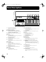


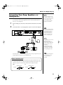
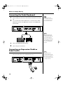
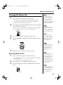


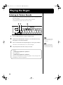


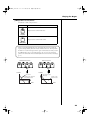


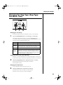


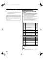
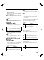
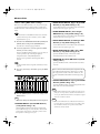
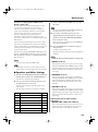


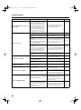

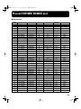
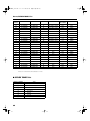
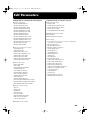


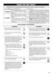
![[1] à - Studio 250](http://vs1.manualzilla.com/store/data/006453244_1-55a19ae5d71d5aa5694f437640df041e-150x150.png)