1
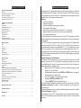
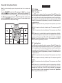
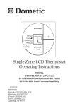
Comfort Control Center 2 Thermostat
Operating Instructions
Programmable Thermostat
MODEL
3312026.XXX With Dehumidify
3312024.XXX With Out Dehumidify
TABLE OF CONTENTS
About your new thermostat
About your new thermostat
Features......................................................................................................................2
System Configuration & Initialization...........................................................................2
Factory preset settings................................................................................................3
Quick reference to control buttons..............................................................................3
Quick reference to LCD icons.....................................................................................3
Congratulations! Your recreational vehicle manufacturer has equipped your RV with
the most advanced RV thermostat. Your Dometic Comfort Control Center 2 thermostat (hereinafter referred to as the CCC 2 thermostat) has been designed for ease of
operation and for many years of reliable service.
Features
• Liquid Crystal Display
• 2 operation programs
• Outdoor temperature sensing (select models)
• Constant time of day display
• Remote Sensor (Precise comfort control within 1º F. of set-point)
• Display reminder lets you know when to service or replace filters
• Up to 4 independent zones
To help familiarize yourself with the operation of the CCC 2 thermostat, review the
following diagrams and accompanying text that explain the functional characteristics
of this system.
Your CCC 2 thermostat is equipped with a liquid crystal display (LCD) that identifies
the mode of operation (OFF, Cool, Heat Pump, Fan, Heat Strip, Auto, & Furnace or
Aqua), temperature set-point, zone identification (1, 2, 3, 4), fan speed (Auto, Low,
Med, High), program 1 and 2, inside temperature, outside temperature, clock, ºF/ºC,
compressor delay, filter maintenance, and dehumidify operation with humidity set
point. The modes of operation viewed in the LCD will vary depending on the system
installed in your RV.
System Configuration & Initialization
The installer of your system will set the required system DIP switches to the ON
position. In order for the CCC 2 thermostat to recognize the system zones, type of
units installed and their options, a system reset must be done. Once the system is
completely installed, do a system reset.
• Make sure the CCC 2 thermostat is in the OFF condition. See page 3, Quick
reference to control buttons.
• Simultaneously press and hold the MODE and ZONE buttons. See page 3,
Quick reference to control buttons.
• The LCD will display “IniT” and all available zones.
• Release the MODE and ZONE buttons.
• Press the ON/OFF button to exit system set up.
The furnace ON/OFF temperature differential should be set at this time. See “Programming & Operations” on page 7 for further information on furnace mode differential setting.
Any time a system reset occurs, the factory default settings are restored. See “Factory Preset Settings” on page 3.
In the unlikely event of CCC 2 system memory loss or dip switch setting change,
the CCC 2 thermostat will require a system reset. Refer to page 11 for system reset
procedure.
Programming & Operations
ON/OFF.......................................................................................................................3
Clock setting................................................................................................................4
Temperature format ºF/ºC............................................................................................4
Inside Temperature......................................................................................................4
Outside Temperature...................................................................................................4
Zone Selection............................................................................................................5
Mode Selection............................................................................................................5
Fan Speed...................................................................................................................5
Temperature Set-Point................................................................................................5
Dehumidify Setting (Select Models)............................................................................6
Mode description
OFF.............................................................................................................................6
Cool. ...........................................................................................................................6
Heat Pump..................................................................................................................6
Heat Strip....................................................................................................................7
Fan . ...........................................................................................................................7
Furnace/Aqua..............................................................................................................7
Auto Change Over.......................................................................................................7
Special Features
Auto Fan......................................................................................................................8
Zone Control................................................................................................................8
Dehumidify (Select Models)........................................................................................8
Program 1 & 2.............................................................................................................8
CANbus.......................................................................................................................9
Auxiliary Heat (Heat Pump Models Only)....................................................................9
Stage Select (Two Air Conditioners/Heat Pump Units)...............................................9
Stage Select (Models Equipped With Two Compressor).............................................9
Automatic Generator Start...........................................................................................10
Load Shed...................................................................................................................10
Defrost Cycle (Heat Pump Models Only)....................................................................10
Compressor Time Delay..............................................................................................10
Power Interruption.......................................................................................................10
LCD Error Codes.........................................................................................................10
System Reset Procedure..........................................................................................11
General Information..................................................................................................12
Maintenance...............................................................................................................12
Service........................................................................................................................12
2
Your Dometic CCC 2 thermostat has been pre-programmed. Review settings below
and adjust the settings to your personal comfort level.
Note: Any time the CCC 2 is in an idle stage (not illuminated) you will need to wake
it up by pressing any button on the CCC 2 before it will recognize a new setting attempt.
Factory Preset Settings
Factory Preset Settings Each Zone
All Zones
Program 1
Function
Setting
Function
Setting
Time of Day (Clock)
———
Heating
68ºF / 20ºC
Cooling
72ºF / 22ºC
Each Zone
Relative Humidity
50%
Automatic
70ºF / 21ºC
Heating
68ºF / 20ºC
Fan Speed
Auto
Cooling
72ºF / 22ºC
Mode
Off
Time
8:00 AM
Automatic
70ºF / 21ºC
Fan Speed
Auto
Mode
Off
Heating
68ºF / 20ºC
Humidity (select models)
Off
Cooling
72ºF / 22ºC
Automatic
70º / 21ºC
Fan Speed
Auto
Quick reference to LCD icons
Operation Mode
Zone
Time of Day
Temperature,
Humidity Set-Point
or Error Code
Program
Mode
Off
Time
10:00 PM
Fan Speed
Compressor
Delay
ON/OFF
To turn ON the CCC 2 thermostat when the back light is off, first press any button
to wake up the CCC 2 thermostat. Then press and release the ON/OFF button. The
LCD will display the last programmed settings. To turn OFF the CCC 2 thermostat
press the ON/OFF button and release. Only the time of day will display when the
CCC 2 thermostat is in the OFF condition.
Press to display
inside temperature
Press to display
outside temperature
Press to select
fan speed
Press to select
temperature format
Press to set
clock
Press to select
program 1 or 2
Press to display relative humidity set-point
(Select Models)
Clean or Replace
Filter
Programming & Operations
Press to increase temperature
or humidity set-point
Press to select
On and OFF
Press to
select mode
Dehumidify
Icon
Program 2
Quick reference to control buttons
Press to select zone
Humidity Set-Point
Percent
Press to decrease
temperature or
humidity set-point
3
Clock Setting
Inside Temperature
Press the CLOCK button to initiate the clock setting sub-menu on the CCC 2 thermostat. When in this menu, the hour digits will flash first. The hour can be adjusted
using the
or
buttons. Press the CLOCK button again and the minute digits
will flash, allowing the minute setting to be adjusted using the
or
buttons.
Press it a third time and the AM or PM icon will flash, allowing the AM or PM setting
to be adjusted using the
or
buttons. Press it one more time to store the new
time in memory and exit the clock setting sub-menu.
Press and hold the INSIDE TEMP button and the LCD will display the current inside
temperature recorded at the CCC 2 Thermostat (or at the optional remote indoor
temperature sensor) instead of the temperature set-point. The LCD will also display
“IN” to indicate that the inside temperature is being displayed. When the INSIDE
TEMP button is released, the LCD will return to the programmed temperature setpoint.
Temperature format ºF / ºC
Outside Temperature
Press and hold the OUTSIDE TEMP button and the LCD will display the current
outside temperature recorded at the outdoor temperature sensor in place of the temperature set-point. The LCD will also display “OUT” to indicate the outside temperature is being displayed. When the OUTSIDE TEMP button is released, the LCD will
return to the programmed temperature set-point.
The outside temperature sensor is located in the roof top unit. The CCC 2 thermostat
temperature measuring range is between -5° F and 105° F. When the roof top unit is
exposed to direct sunlight, the upper limit of the CCC 2 thermostat could be reached
even though the actual outdoor temperature is lower than 105° F. Outside temperatures above 105° F will be displayed as 105 ° F.
Press the ºF / ºC button to switch between Fahrenheit and Centigrade format. ºF
indicates Fahrenheit and ºC indicates Centigrade
4
Zone Selection
Fan Speed
Press the Zone button to cycle the LCD display through the available zone selections; Zone 1, Zone 2, Zone 3, and Zone 4. Only the available zones installed within
your system will display. See “Special Features” on page 8 for more information
on zones.
Press the FAN button to select the desired fan speed. Each successive press will
advance to the next available speed. Your selections will be Auto, LOW, MED, and
HIGH. The fan will run continuously during LOW, MED, and HIGH fan settings. The
fan will cycle on and off with the thermostat on AUTO setting. See “Special Features” on page 8 for more information on auto fan.
Mode Selection
Temperature Set-Point
Press the MODE button and the LCD will display the first available mode. Each successive press will advance to the next available mode. Continue to press the MODE
button until the desired mode appears. Depending on the systems installed, your
choices will be OFF, COOL, AUTO, HP, FURN or AQUA, HS, and FAN. See “Mode
Description” on page 6-7 for more information on modes.
Press the
or
button to change the temperature set-point. The temperature set-point is indicated by two digits on the LCD. Press
to increase and
to decrease the temperature set point. The maximum set-point for the system is
90º F. The minimum set-point is determined by the active operating mode. For heating, the minimum is 40º F. and minimum for cooling is 55º F.
5
Dehumidify Setting (Select Models)
Mode Description
Note: To set the dehumidify set-point, the system will need to be in a mode other
than OFF.
Press the DEHUMIDIFY button. The LCD will display the “dEHm” icon, the water
droplet icon
, and the humidity set-point. The set-point can be adjusted in 5% increments from 35% to 70%. Press the
button to increase the set-point and
the button to decrease the set-point. To disable the dehumidify operation, press
and hold the DEHUMIDIFY button for three (3) seconds. The water droplet icon will
be turned off and returns to the previous settings.
“OFF” - Off Mode
Displays OFF mode in a zone.
“COOL” - Cool Mode
In the COOL mode the system will cycle the compressor ON and OFF based on the
room air temperature and the temperature set-point on the CCC 2. When the system
calls for cooling there will be a delay of approximately two minutes. During this delay,
the hour glass icon will be displayed in the LCD. In auto fan, the fan will turn ON first
followed by the compressor in approximately 15 seconds. In this mode there are 4
fan speed selections:
LOW: The fan operates continuously at low speed. The compressor cycles On and
OFF.
MED: The fan operates continuously at medium speed. The compressor cycles ON
and OFF.
HIGH: The fan operates continuously at high speed. The compressor cycles ON and
OFF.
AUTO: When auto fan is selected the fan speed will vary depending on the difference between the temperature set-point and the room temperature. In auto fan the
compressor and the fan will cycle ON and OFF with the thermostat. See “Special
Features” on page 8 for information on auto fan. The compressor shuts off first followed by the fan in approximately 15 seconds.
“HP” - Heat Pump Mode
In the HP mode the system will cycle the compressor ON and OFF based on the
room air temperature and the temperature set-point on the CCC 2. When the system
calls for heating there will be a delay of approximately two minutes. During this delay,
the hour glass icon will be displayed in the LCD. In auto fan, the compressor will turn
ON first followed by the fan in approximately 15 seconds. In this mode there are 4
fan speed selections:
LOW: The fan operates continuously at low speed. The compressor cycles On and
OFF.
MED: The fan operates continuously at medium speed. The compressor cycles ON
and OFF.
HIGH: The fan operates continuously at high speed. The compressor cycles ON and
OFF.
AUTO: When auto fan is selected the fan speed will vary depending on the difference between the temperature set-point and the room temperature. In auto fan the
compressor and fan will cycle ON and OFF with the thermostat. The compressor
shuts off first followed by the fan in approximately 15 seconds. See “Special Features” on page 8 for information on auto fan.
6
“HS” - Heat Strip Mode
In the HS mode the system will cycle the heat strip ON and OFF based on the room
air temperature and the temperature set-point on the CCC 2 thermostat. In this mode
there are 4 fan speed selections:
LOW: The fan operates continuously at low speed. The heat strip cycles On and
OFF.
MED: The fan operates continuously at medium speed. The heat strip cycles ON
and OFF.
HIGH: The fan operates continuously at high speed. The heat strip cycles ON and
OFF.
AUTO: The fan operates in low speed and will cycle ON and OFF with the thermostat.
“AUTO” - Auto Change Over Mode
In the AUTO mode the system will automatically change the mode of operation from
cool to heat or from heat to cool. In order for this mode to operate, the zone being
programmed must contain either a heat pump, heat strip or furnace heating source.
When in the AUTO mode, all pre programmed operations for the heat pump, heat
strip, and furnace will apply.
Auto Change Over Cooling: If the room temperature rises above the temperature
set-point by 2 degrees, the air conditioner will turn ON until the room temperature
reaches the temperature set-point at which time the air conditioner will cycle off.
Auto Change Over Heating: If the room temperature goes below the temperature
set-point by 2 degrees, the available heat source will be cycled ON until the room
temperature reaches the temperature set point at which time it will cycle OFF.
If more than one heat source is available on this zone, the priority for selecting the
heat source will be heat pump (first), furnace (second), and heat strip (third).
“FAN” - Fan Mode
In FAN mode there are 4 fan speed selections:
LOW: The fan operates continuously at low speed.
MED: The fan operates continuously at medium speed.
HIGH: The fan operates continuously at high speed.
AUTO: The fan will be OFF.
“FURN” / “AQUA” - Furnace or Aqua Mode (Factory setting is “FURN”)
To change the setting from “FURN” to “AQUA” or visa versa, simultaneously press
the
up and
down buttons. The LED will display the selected option.
In the FURN/AQUA mode the system will cycle the RV’s furnace/aqua ON and OFF
based on the room air temperature and the temperature set-point on the CCC 2
thermostat. The system can be configured to operate using an ON/OFF differential
of either 1 degree F. or 2 degree F. This feature is programmed during the system
initialization. See “System Configuration & Initialization” on page 2. To set the
1 degree differential, simultaneously press PROGRAM button and
up button
(“dIF1” will appear in the display while the buttons are pressed). To set the 2 degree
differential, simultaneously press the PROGRAM button and the
down button
(dIF2” will appear in the display while the buttons are pressed). In this mode there
are 4 fan speed selections:
LOW: The fan operates continuously at low speed.
MED: The fan operates continuously at medium speed.
HIGH: The fan operates continuously at high speed.
AUTO: The fan is off.
7
When the freeze sensor temperature is 27º F. or less. Resumes when freeze
sensor temperature reaches 55º F.
• If the system detects an error on any of the system temperature sensors.
When the system calls for furnace operation, the dehumidify feature will continue to
operate unless one of the conditions above occurs.
Special Features
Auto Fan
When auto fan is selected the fan speed will vary depending on the difference between the temperature set-point and the room temperature. In auto fan the compressor and fan cycle On and OFF with the thermostat.
When the difference is:
8º or more
The fan operates on HIGH
5º to 7º
The fan operates on MED
4º or less
The fan operates on LOW
Program 1 & 2
The Dometic CCC 2 thermostat can store two operating programs. Each program
can be set on individual zones with different mode and time settings for each zone.
For each event the user can program the operating mode, fan speed, temperature
set-point, and the time of day for the event.
1. Select the zone to be programmed.
2. Select program 1 by pressing the PROGRAM button. “PROG 1” icon will blink
on the LCD display.
3. Press the CLOCK button to set the time of day for program to start.
4. Press the MODE button to select the mode of operation.
5. Press the FAN button to select the fan speed.
6. Press the PROGRAM button to save the “PROG” 1 settings. LCD will now show
“PROG 2”.
To set program 2, repeat steps 3 - 5.
Zone Control
Zones are established at the time of the installation of your Dometic CCC 2 thermostat. A zone is an area of cooling/heating which is controlled independently by the
CCC 2 thermostat. The CCC 2 thermostat allows for four zones (Air Conditioner/
Heat Pump) to be set up and run independent of each other. If you have one air conditioner/heat pump installed, you will have one zone. If your RV has more than one
cooling/heating system, you may have 2, 3, or 4 zones.
Your CCC 2 thermostat will operate cooling and heating appliances that your vehicle
manufacturer has designed to cool or heat specific areas (zones) of your RV. The
CCC 2 thermostat will advise you of the number of zones in your RV. The zones are
displayed 1, 2, 3, or 4 in the LCD readout. See “Quick reference to icons” on page
3. In the event your vehicle has multiple zones designed, you have the freedom of
selecting different modes of operations for each zone. To change from one zone
to another, press the ZONE push-button on the CCC 2 thermostat. Each time the
button is pressed and released the indicator will change the zone data displayed.
When the zones have been programmed, the zones in operation will be displayed.
To program each zone, simply repeat the programming steps shown in the operation
section of this manual.
Press the Program button again to save programs in memory. Depending on the
time of day, program 1 or 2 will begin immediately. For instance, if program 1 is set to
begin at 10:00 AM and the time of day is 10:30 AM, program 1 will begin immediately.
On the other hand, if program 1 is set to 10:00 AM and program 2 is set to begin at
6:00 PM and the time of day is 7:00 PM, program 2 will begin immediately.
Dehumidify (Select Models)
The Dometic CCC 2 thermostat will accommodate only one dehumidify air conditioner within the four zones. The dehumidify air conditioner can either be zone 1, 2,
3, or 4. The dehumidify air conditioner must have the DEHUMIDIFY dip switch set to
the ON position when the unit is installed.
When the relative humidity is above the humidity set-point the compressor will cycle
ON and if the fan is in the AUTO mode it will run on LOW speed. If LOW, MED or
HIGH speed is selected the fan will run in the speed selected. When the humidity is
5% or less than the humidity set-point the compressor will cycle OFF.
The dehumidify feature does not permit operation under the following conditions:
• Outdoor temperature is below 40º F. Resumes operation above 45º F.
• Indoor temperature is below 62º F. Resumes operation above 65º F.
• Indoor temperature is above 100º F. Resumes operation below 97º F.
• When the zone with dehumidify is set to COOL mode and the indoor temperature is 2º F. above the COOL mode set-point. Resumes operation when
indoor temperature is 2º F. below COOL mode set-point
•
8
Auxiliary Heat (Heat Pump Models Only)
Examples of times programmed
Auxiliary heat operation will be activated when the measured temperature of the outdoor temperature sensor is less than 30º F. If the system is equipped with a furnace,
the control will select FURN heating mode for the auxiliary heat source. Auxiliary
heat operation, once initiated, will have priority over a heat pump defrost cycle.
Auxiliary heat operation will be de-activated and the heat pump operation will resume when the temperature of the outdoor temperature sensor is higher than 35º F.
Stage Select - Two Air Conditioner/Heat Pump Units (Select Models) On 1 Zone
This system can be configured to run two air conditioner/heat pump units using the
same temperature set-point for controlling the comfort level in one zone. One unit is
designated as the primary stage and the other unit is designated as the secondary
stage. The power module boards in both units will use the same DIP switch selection
for the Zone (for example, both will be set to Zone 2). On the unit designated “secondary” the power module board DIP switch identified as “Ext Stage” must be set
to the ON position in order to configure the power module board for the on-demand
secondary stage operation (in this example Zone 2 and Ext Stage DIP switches are
in the ON position). In this stage configuration, the CCC 2 thermostat temperature
set-point will be used for both the primary and the secondary stage air conditioner/
heat pump. Only one indoor temperature sensor is required for this configuration
and it must be installed in the power module board configured as the primary control.
The turn ON time for the compressors and fans will be controlled to ensure that compressors on the system start one-at-a-time. A minimum delay of 20 to 30 seconds is
required between compressor starts.
Stage Select - Dual Compressor Air Conditioner/Heat Pump (Select Models)
The Dometic CCC 2 thermostat will operate an air conditioner/heat pump unit with
two compressors. On dual basement air conditioner/heat pumps, a single power
module board is used to control the operation of two compressors in one air conditioner/heat pump. This system is designed to optimize comfort and operating efficiency by providing an on-demand secondary stage of operation. The CCC 2 thermostat will allow the user to set the primary temperature set-point. The set-point
for the secondary stage is preset at a differential of 3 degrees Fahrenheit from the
primary temperature set-point (that is , +3º F. for cooling and -3º F. for heating).
Example: In the cooling mode with the set-point set to 72º F., the primary air conditioner will cycle ON when the room temperature is ≥ 73º F. The secondary stage
compressor will cycle ON when the temperature is ≥ 75º F. In the heating mode with
the set-point at 72º F., the primary compressor will cycle ON when the temperature is
≤ 71º F. The secondary stage compressor will cycle ON when the room temperature
is ≤ 69º F.
When program 1 or 2 is operating, the “PROG 1 or 2” icon will be displayed
in the LCD. The zone will continue to operate in the programmed setting until the
program is manually cancelled.
To cancel the program operation, press and hold the PROGRAM button for 3 seconds. The zone will be restored to normal operation.
CANbus Interface
The CANbus interface is designed to communicate between the Dometic CCC 2
thermostat and a CAN (Controller Area Network) protocol generator. Refer to the
CANbus installation instructions for more information on installation and operation
of the CANbus.
9
Auto Generator Start (AGS)
Compressor Time Delay
On RV’s equipped with an optional AGS Kit, the vehicle generator will automatically
start when any zone calls for cooling and will shut off when zones reach set point.
The Auto Generator Start (AGS) function will be implemented by an individual power
module board configured for this function by setting the GEN Start DIP switch ON.
On the AGS power module board a relay shall be used to provide a start signal to
the generator. The normally open relay contacts are utilized and the closure of these
contacts provides the signal to start the generator. The AGS relay shall be activated
when any zone or stage requires cooling, heat pump, dehumidifier or heat strip operation. When a zone calls for heating, cooling or dehumidification, the AGS relay shall
be closed, followed by a time delay to allow the generator to warm up after which
time the output relay will be activated on the zone that initiated the heating, cooling or
dehumidification request. When the heat/cool and dehumidify requests in all zones
have been satisfied, the AGS relay will open and the generator will shut-down.
A time delay of approximately two minutes occurs any time the compressor is required to begin the cooling or heat pump cycle.
Power Interruption
In the event the power to the air conditioner or control is interrupted, the system will
restart with the previous set points once power is restored.
LCD Error Code
When the system determines that one of the faults listed below has occurred an error
code will be displayed in the LCD for the zone in which the error occurred. During
normal operation, a blinking zone number indicates a fault has occurred. The error
code is displayed in place of the temperature set-point.
Error Code:
E1 Loss of communication between the CCC 2 thermostat and all system power
module boards. System will shut down.
E1 Loss of communication between the CCC 2 thermostat and an individual system
power module board. The LED will display error code EI and the zone number that lost communication. Any additional zones that loose communication will
blink in addition to the current zone.
E2 Open circuit or out-of-range indoor temperature sensor. All heat , cool, and dehumidify operations will be locked out. Manual fan operation will continue.
E3 Shorted Indoor Temperature Sensor. All heat, cool, and dehumidify operation will
be locked out. Manual fan operation will continue.
E4 Open circuit or out of range Outdoor Temperature Sensor (select models). Heat
pump and dehumidification operation will be locked out. Air conditioner, furnace,
heat strip and fan operation can continue to operate.
E5 Open circuit or out of range Freeze Sensor. Air conditioner and dehumidification
operation will be locked out. Heat pump, furnace, heat strip and fan operation
can continue to operate but displays the last temperature set-point.
E6 Open circuit Humidity Sensor (Select Models). Air conditioner and dehumidification will be locked out. Heat pump, furnace heat strip and fan can continue to
operate.
E7 Loss of 120 VAC power to all power module boards on the system. The system
will shut down.
E8 Invalid zone configuration. The heat pump and heat strip DIP switches are both
set to the ON position in one zone. Heat pump, heat strip, air conditioner, and
dehumidify operation will be locked out in the affected zone.
E9 Invalid zone configuration. The dehumidifier DIP switch and either the heat pump
or heat strip DIP switches are set to the ON position in one zone. Heat pump,
heat strip, air conditioner, and dehumidify operation will be locked out in the affected zone.
Load Shed
The Dometic CCC 2 thermostat has provisions for Load Shedding. The AC power
module board shall provide the 12 VDC source for the Load Shed signal. This 12
VDC source shall be turned ON one second before the compressor relay when the
system calls for the compressor to be ON. The Load Shed source shall remain on
when compressor is caused to turn OFF due to being disable by either a Freeze
Sensor or a Load Shed condition. The load shed source signal will be switched to
the Load Shed input by the normally open contacts or an off-board relay from the RV
power management system. When the Load Shed signal is detected, the compressor shall turn OFF.
Defrost Cycle (Heat Pump Models Only)
To avoid frost formation on the outside coil and to obtain maximum performance
when the outside temperature is less than 42º F. and greater than 30º F., a defrost
cycle will be initiated. While operating in this temperature range the compressor continuous run time is limited to 25 minutes. When this time is accumulated, the fan will
shut off, the refrigerant flow will be reversed, and the compressor will continue to run
for 4.5 minutes. During this 4.5 minute period, the LCD will toggle between HP and
Defrost. The refrigerant flow will then be reversed and after a 30 second delay the
fan will resume operation. This cycle will remove any frost formation on the outside
coil. This cycle will repeat itself until the outside temperature is greater than 42º F. If
the outside temperature becomes less than 30º F. the heat pump will shut OFF and
the auxiliary heat (if provided) will turn on.
10
System Reset Procedure
When your unit was installed the appropriate dip switches on the electronic control
board were turned on to match your system configuration. Any time these settings
are changed, a system reset will need to be done before the CCC 2 thermostat will
recognize the updated selection. To do a system reset:
• Make sure the CCC 2 thermostat is in the OFF mode.
• Simultaneously press the MODE and ZONE buttons. The LCD will display
“IniT” and all available zones.
• Release the MODE and ZONE buttons.
• Press the ON/OFF button to exit system set up.
This space intentionally left blank
11
General Information
Service
A. The ability of the air conditioner to maintain the desired inside temperature depends on the heat gain of the RV. Some preventative measures taken by the
occupants of the RV can reduce the heat gain and improve the performance of
the air conditioner. During extremely high outdoor temperatures, the heat gain of
the vehicle may be reduced by:
1. Parking the RV in a shaded area.
2. Using window shades (blinds and/or curtains).
3. Keeping windows and doors shut or minimizing usage.
4. Avoiding the use of heat producing appliances.
In the unlikely event the unit fails to operate or operates improperly, check the following before calling your service center.
1. If your RV is connected to a motor generator, check to be sure the motor generator is running and producing power.
2. If the RV is connected to a power supply by a land line, check to be sure the line
is sized properly to run air conditioner load and it is plugged into the power supply.
3. Check your 120 VAC fuse or circuit breaker to see if it is open. Insure fuse is not
burnt, or circuit breaker is ”ON” and not activated.
4. Check your 12 VDC fuse or circuit breaker to see if it is open.
5. After the above checks, call your local service center for further help. This unit
must be serviced by qualified service personnel only.
Operation on High Fan/Cooling mode will give optimum or maximum efficiency
in high humidity or high outside temperatures.
Starting the air conditioner early in the morning and giving it a "head start" on
the expected high outdoor ambient will greatly improve its ability to maintain the
desired indoor temperature.
For a more permanent solution to high heat gain, accessories like A&E outdoor
patio and window awnings will reduce heat gain by removing the direct sun. They
also add a nice area to enjoy company during the cool of the evening.
When calling for service, always give the following:
1. Unit Model Number and Serial Number found on Identification Label located on
the Base Pan of unit bottom. It is necessary to remove the return air cover to
expose the rating plate.
2. Electronic Control Kit Part Number and Serial Number found on Identification
Label located on the side of the Kit. This kit is mounted in the return air cavity
and can be exposed by removing the return air cover.
B. The manufacturer of this air conditioner will not be responsible for damage caused
by condensed moisture on ceilings or other surfaces. Air contains moisture and this
moisture tends to condense on cold surfaces. When air enters the RV, condensed
moisture may appear on the ceiling, windows, metal parts, etc. During normal
operation, this unit removes moisture from the air. Keeping doors and windows
closed when this air conditioner is in operation will minimize condensed moisture
on cold surfaces.
USA
SERVICE OFFICE
Dometic, LLC
2320 Industrial Parkway
Elkhart, IN 46516
574-294-2511
Maintenance
Air Filter - Periodic cleaning or replacement of the air conditioner/heat pump air
filters is required. When a system fan run time exceeds 1000 hours the filter icon is
displayed in the LCD. See “Quick reference to LCD icons” on page 3. When this
occurs wash the filter with soap and warm water. Let dry and reinstall. NEVER run
the air conditioner without the air filter in place. This may plug the unit evaporator coil
with dirt and substantially degrade the performance of the unit.
To reset the fan run time and clear the filter icon, hold the INSIDE and OUTSIDE buttons for three seconds. This will clear the fan run time for the current zone selected.
Dometic CCC 2 thermostat: Clean the CCC 2 thermostat with a moist soft cloth.
DO NOT spray water directly on the CCC 2 thermostat. DO NOT use solvents for
cleaning.
CANADA
Dometic, LLC
46 Zatonski, Unit 3
Brantford, ON N3T 5L8
CANADA
519-720-9578
For Service Center
Assistance Call:
800-544-4881
12
3312366.010
REVISION
Form No. 3312366.010 7/10
(Replaces 3312366.000)
(French 3312796.018)
©2010 Dometic, LLC
Lagrange, IN 46761