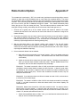
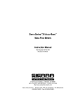
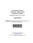
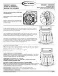
1
Series 240/241 Instruction Manual
Table of Contents
Sierra Series 900
Single & Dual Channel System
Instruction Manual
Part Number IM-90-1
07/05 Revision D.1
5 Harris Court, Building L Monterey, CA 93940
(831) 373-0200 (800) 866-0200 Fax (831) 373-4402
http://www.sierrainstruments.com
Sierra Instruments b.v. Bolstoen 30A 1046 AV Amsterdam The Netherlands
+31(0)20-6145810 Fax +31(0)20-6145815
IM-24-C
0-1
Series 900 Single & Dual Instruction Manual
CUSTOMER CAUTION
RE: OXYGEN SERVICE
Sierra Instruments, Inc., is not liable for any damage or personal injury, whatsoever, resulting from
the use of Sierra Instruments mass flow meters or
controllers for oxygen gas. Although Sierra cleans
its mass flow meters and controllers prior to shipment, we make no claim or warranty that their
cleanliness renders them safe for oxygen service.
The customer must clean Sierra Instruments mass
flow meters or controllers to the degree required
for the customer’s oxygen flow applications.
© COPYRIGHT SIERRA INSTRUMENTS 1994
No part of this publication may be copied or distributed, transmitted, transcribed, stored in a retrieval system, or translated
into any human or computer language, in any form or by any means, electronic, mechanical, manual, or otherwise, or
disclosed to third parties without the express written permission of Sierra Instruments. The information contained in this
manual is subject to change without notice.
TRADEMARKS
Side-TrakTM and Flo-BoxTM are trademarks of Sierra Instruments Inc.
Page 16
Series 900 Single & Dual Instruction Manual
1. Introduction ............................................................................. 1
2. Locating System Electronics .................................................. 2
TABLE OF
CONTENTS
3. Front Panel Functions ............................................................ 3
3.1 ChannelSelection .............................................................. 3
3.2 Reading Flow Value .......................................................... 3
3.3 Flow Setpoint Display and Adjustment ................................ 3
3.4 High/Low Alarm Display and Adjustment ........................... 3
3.5 Totalize (Mass Flow Integration) Function ........................... 4
3.5 3.5.1 Reset Totalize Function ........................................... 4
4. Rear Panel Connections ........................................................ 5
4.1 Power Line and Fuse .......................................................... 5
4.2 20-Pin Connectors for Sierra Flow Meters/Controllers .......... 5
4.3 26-Pin I/O Connector ......................................................... 5
4.4 4.3.1 Flow Value Output 0-5 VDC and 4-20 mA................ 5
4.4 4.3.2 Valve Off/Purge/Monitor ......................................... 5
4.4 4.3.3 High/Low Flow Alarm Outputs ................................ 6
4.4 Automatic/ManualSetpointSelection .................................. 6
5. Maintenance ........................................................................... 7
5.1 DisplayAdjustment ........................................................... 7
5.2 Zen and Span Adjusted ...................................................... 7
5.3 Factory Service ................................................................. 7
Appendix A: Specifications ........................................................... 8
Appendix B: Back Panel Connector, 20-Pin .................................... 9
Appendix C: Back Panel Connector, 26-Pin .................................. 10
Appendix D: Alarms for System Electronics .................................. 11
Appendix E: Wiring Guide .......................................................... 12
Appendix F: Ratio Control Option ................................................ 13
Page 15
Series 900 Single & Dual Instruction Manual
The Sierra Instruments, Inc. Single and Dual Channel System
Electronics is a highly integrated systems solution to flow measurement and control.
1
INTRODUCTION
One or two independent flow meters or controllers can be operated
simultaneously.
Linear operation with LCD readout is standard.
The back panel connectors provide outputs of 0-5 VDC and 4-20
mA and are 0-100% analogs of the flow range. Both voltage and
current outputs are simultaneously available.
Flow setpoint for flow controllers is from either the front panel
adjustment potentiometers or a remote source via the back panel
I/O interface. These potentiometers are only available on system
electronics which have a “C” as part of the model number (i.e.,
902C).
Side-Trak mass flow controllers also incorporate valve purge/
monitor/off functions which are accessible from the back panel
I/O connector.
Each channel has an optional high and/or low alarm (open collector) output. The alarm adjustment pots are located inside the
system electronics box and can be read on the front panel display
during adjustment.
An optional built-in totalizer on single channel configurations
displays the total mass flow. The electronic totalizer is highly
immune to power line interruptions.
The power supply is a linear (non-switching) laboratory quality
unit capable of easily supplying power to 2 channels simultaneously.
Page 1
Series 900 Single & Dual Instruction Manual
The System Electronics should be located in a room-temperature
location which is dry and dust-free. Use cable lengths in accordance with the guidelines given with your transducer. Excessive
cable lengths will impair operation of both the System Electronics
and the transducer.
2
LOCATING SYSTEM
ELECTRONICS
Extremes of temperature and direct sunlight should be avoided.
Choose a location which allows the readout to be easily viewed.
Page 2
Series 900 Single & Dual Instruction Manual
System Electronics’s front panel controls provide ease of operation. To get the most benefit from a Sierra Instruments, Inc.
System Electronics, read these instructions before attempting
operation.
3
FRONT PANEL
FUNCTIONS
On dual channel units, the rotary switch labeled Channel Select
determines which channel is displayed.
3.1
Channel Selection
The flow value is normally read from the LCD Display. Readout
is usually in engineering units and is indicated on the label.
3.2
Reading Flow Value
System Electronics toggles between flow reading and flow setpoint
by the switch labeled “SET/READ”. When in the READ mode, the
display shows flow value as above. When in the SET mode, the
display shows the current setpoint value in the same units as the
“READ” mode.
3.3
Flow Setpoint Display
and Adjustment
(Controllers Only)
For each channel, there is an optional high alarm and/or low
alarm. Each alarm output is active whenever the flow is above or
below the preset value, respectively. All alarm outputs are OPEN
COLLECTOR NPN and sink current to COMMON. If driving a
relay, a reverse polarity protection diode must be connected across
the coil. See appendix D for additional information regarding the
alarms.
3.4
High/Low Alarm Display
and Adjustment
When the flow is below the low alarm set value, the low alarm is
active. (Alarm is ON).
When the flow value is greater than the high alarm set value, the
high alarm is active. (Alarm is ON).
The alarm adjustments are located internally. The front bezel
must first be removed by unscrewing the four black screws
holding it in place, then sliding the top cover out to expose the
main printed circuit board. See the drawing in Appendix G giving
the location of the alarm component.
The alarm display is activated using internal switches. These
switches are located near the front panel. The switch labeled ALM
or NORM shows the alarm setting on the front panel display. The
toggle switch labeled HI/LO selects whether the high or low alarm
is displayed. This switch must be held at the ALM position while
adjusting the alarm point with the switch in the ALM position, the
LCD display will show the alarm value.
The alarm adjustment potentiometers are located toward the rear
of the main PCB. As you face the front of the unit, Channel 1 is on
the right and Channel 2 is on the left. The high alarm pots are
marked R29 and the low alarm pots are marked R33.
Page 3
Series 900 Single & Dual Instruction Manual
As the potentiometer is rotated the appropriate alarm setpoint is
varied from zero to the full scale flow value and displayed in the
front LCD display.
The totalize option records the total mass flow. This value is
indicated on the front panel electronic counter and is therefore
immune to power line interruptions.
3.5
Totalize (Mass Flow
Integration) Function
Counter has battery back-up that uses two 1.5 alkaline “N” size
cells.
The totalizer reading may be reset to all zeros by depressing the
button next to the totalizer display window.
3.5.1
Reset Totalize Function
Page 4
Series 900 Single & Dual Instruction Manual
The AC power line connector (or power entry module) is located on
the back panel. A cordset is supplied with the System Electronics
and is compatible with wall outlets in the USA. Be sure System
Electronics is wired for the proper power mains voltage, either 115
VAC, 60 Hz or 230 VAC, 50/60 Hz, as indicated on the label. If you
wish to change the receptacle configuration, you may use any
standard CEEE 22 cordset to accomplish this.
4
REAR PANEL
CONNECTIONS
4.1
Power Line and Fuse
The fuse is an integral part of the AC power connector. To remove
the fuse, turn the front panel power switch OFF then remove the
cordset from the back panel power connector. With the cordset
removed, a small door built into the back panel power connector
can now be flipped out exposing the fuse holder. In USA System
Electronics there is a single gray fuse holder which can be
unclipped and pulled out by hand. The fuse is an AGC type 3 amp
rating. Replacement fuses are widely available.
The back panel has two 20-pin headers labeled Channel 1 and
Channel 2. Each channel is set-up for a specific transducer. Be
sure that the serial number on the side of the transducer agrees
with the rear panel label. Normally, cables are prewired and the
entire system is set-up at the factory. Pin assignments are given
in Appendix B.
4.2
20-Pin Connectors for
Sierra Flow
Meters/Controllers
CAUTION! Do not plug a transducer into the wrong channel, as
flow values may be extremely inaccurate and/or damage may
result to system electronics and transducer.
The 26-Pin I/O Connector on the back panel is the means to access
many of the System Electronics functions such as flow outputs,
valve override and monitoring, etc. The following section covers
these functions in detail. Refer to Appendix B for pin assignments.
4.3
26-Pin I/O Connector
The 26-pin I/O connector provides two analog outputs for each
channel. One provides a 0-5 VDC LINEAR analog of the flow value
referred to common. The other supplies a 4-20 mA LINEAR
analog of the flow value referred to +15 VDC. Both outputs are
always present for all channels. Refer to Appendix B for pin
assignments.
4.3.1
Flow Value Output
0-5 VDC and 4-20 mA
The 26-pin I/O connector has connections for Side-Trak controller
systems to drive the valve fully closed or fully open. Also, the
voltage across the valve may be monitored to help in valve
adjustment.
4.3.2
Valve Off/Purge/Monitor
(Side-Trak
Controllers Only)
If the VALVE OFF pin for a channel is connected to common, the
valve is closed regardless of setpoint. This pin is TTL compatible.
Refer to Appendix C for pin assignments.
Page 5
Series 900 Single & Dual Instruction Manual
The VALVE PURGE function is activated by the VALVE TP (test
point) pin. When this pin is connected to common, the valve is fully
open regardless of setpoint. This pin must source 150 mA of
current when driven to common. If a voltmeter is connected
between this pin and –15 VDC, the voltage across the valve coil
may be read. Refer to Appendix C for pin assignment.
The 26-pin connector has two optional alarm outputs per channel.
One is active when the flow drops below a preset value (low alarm).
The other is active when the flow increases above a preset value
(high alarm). All alarm outputs are open collector. Maximum
current is 100 mA per alarm. Maximum “standoff” voltage is 30
VDC.
4.3.3
High/Low Flow
Alarm Outputs
CAUTION! If a relay is being driven by an alarm, A protection
diode must be connected across the relay coil with reversed
polarity.
A high and low alarm may be connected in parallel to make a
window alarm. Whenever the flow is inside of the window defined
by the two alarms, the alarm is inactive (OFF). If the flow is
outside of the window, the alarm is active (ON). See Appendix D
for suggested alarm configurations.
There are two plastic programming jumpers plugged into a header
on the back panel. For each channel they determine whether the
0-5 VDC setpoint input comes from the front panel pots (MANUAL)
or from the 26-pin I/O connector (AUTOMATIC). These jumpers
are easily changed in the field simply by unpluging them and
moving them to the other position. The system will not function as
a control box for mass flow controllers without these jumpers.
4.4
Automatic/Manual
Setpoint Selection
(Controllers)
Page 6
Series 900 Single & Dual Instruction Manual
Normally each System Electronics is carefully set-up at Sierra
Instruments and needs no maintenance. Individual transducers
may need periodic maintenance. Refer to transducer manuals for
the proper procedure.
5
MAINTENANCE
The full scale value of the display can be adjusted using the
Display Adjustment Potentiometers, R49 for Channel 1 and R48
for Channel 2. To adjust the span valve of the display, connect a
precision 5 VDC input to pin 3 or a 20 mA input to pin 9 on the 20
pin connector for the appropriate channel. Adjust the corresponding potentiometer to change the span to the desired full scale
value.
5.1
Display Adjustment
The location of the decimal point can be changed using jumpers
located at J5 – J7. There is one set of jumper connectors for each
channel. The following identifies the jumper number and decimal
point location:
J–7
J–6
J–5
1 digit
2 digit
3 digit
(1xx,x)
(1x,xx)
(1,xxx)
The Zen and Span Adjustment Potentiometers (R12 and R16) are
factory adjustments used to set the individual meter to the system
electronics. Sierra recommends that these potentiometers not be
adjusted in the field. Consult with Sierra’s Customer Service
Department at (408) 373-0200 for assistance.
5.2
Zen and Span Adjusted
In the unlikely event of System Electronics malfunction, please
contact our sales engineers or customer service at (800) 866-0200
outside California, or (408) 373-0200 inside California. Ship all
systems to:
5.3
Factory Service
Sierra Instruments, Inc.
5 Harris Court, Bldg. L
Monterey, CA 93940
Attention: Service Department
Be sure to include complete return shipping instructions. IT IS
NOT POSSIBLE TO DELIVER PARCELS TO A POST OFFICE BOX.
In order to minimize the possibility of damage in shipment, the
system should be shipped in its original packing carton. If the
original carton is not available, follow this packing procedure:
1) place bail in front of the unit to protect the front panel;
2) leave rear panel header latches open;
3) pad all sides.
Page 7
Series 900 Single & Dual Instruction Manual
GENERAL
System Electronics Powers/Reads up to two transducers. Flow, Setpoint,
High Alarm, and Low Alarm directly displayed in engineering units. (Linear
models). Outputs 0-5 volts and 4-20 mA for each channel. Valve control
functions of Close/Purge/Monitor. Built-in 10 turn precision setpoint potentiometers. Totalizers (optional) mass flow.
APPENDIX A
Specifications
INPUT POWER
115 VAC ± 10%
230 VAC ± 10% (optional)
OUTPUT POWER
+15 VDC @ 1.25 A
–15 VDC @ .90 A
OUTPUT HUM AND NOISE
Less than .05 Volts RMS
AMBIENT TEMPERATURE RANGE
At full rated power: 0-45°C.
At half rated power: 0-60°C.
RELATIVE HUMIDITY
0-50% non-condensing
DISPLAY
31⁄2 digit LCD in engineering units or 0-100% analog.
CONTROLS
Power ON/OFF. Channel Select (two channel configurations). Total mass
flow reset (with totalizer only). One or two precision 10 turn Setpoint pots as
required (for controllers only).
INPUTS
0-5 VDC and 4-20 mA for each channel (jumper selected on PCB).
OUTPUTS
0-5 VDC and 4-20 mA for each channel.
0-5 VDC is referred to common.
4-20 mA is referred to +15 VDC.
ALARMS (Optional)
Low Alarm and High Alarm open collector output for each channel. Able to
sink 100 mA to common. Stand-off voltage 30 VDC. Independently set by
internal pushbuttons/pots. Uses front panel display to show alarm points.
TOTALIZER
Totalizer has 6-digit capacity.
DIMENSIONS
3"H x 9"W x 11"D (without rack mounting ears)
WEIGHT
7 pounds
Page 8
Series 900 Single & Dual Instruction Manual
KEY
A B C D E
F▼ G H
APPENDIX B
I
J
• • • • • • • • • •
Back Panel Connector
Pin Assignments; 20-Pin
Transducer Connector
• • • • • • • • • •
1 2 3 4 5 6 7 8 9 10
(View of connector from back of enclosure)
PIN NO.
FUNCTION
A
Setpoint Output to
Controllers
B
Common
C
Common
D
Valve Test Point
(Avail. I/O Connector)
E
RED Connection
(Factory Use Only)
F
–15 VDC supply from
System Electronics
to Transducers
PIN NO.
FUNCTION
1
Chassis Ground
2
Common
3
0-5 Volt Signal from
Transducer
4
+15 VDC Supply from
System Electronics to
Transducers
5
BLACK Connection
(Factory Use Only)
6
No Connection
7
No Connection
8
+15 VDC Supply from
System Electronics to
Transducers
G
No Connection
H
High Alarm Output
(Avail. I/O Connector)
I
Low Alarm Output
(Avail. I/O Connector)
9
4-20 mA Signal from
Transducer
J
Valve Off
(Avail. I/O Connector)
10
Common
Page 9
Series 900 Single & Dual Instruction Manual
KEY
A B C D E F G ▼H
I
APPENDIX C
J K L M
• • • • • • • • • • • • •
Back Panel Connector
Pin Assignments; 26-Pin
I/O Connector
• • • • • • • • • • • • •
1 2 3 4 5 6 7 8 9 10 11 12 13
(View of connector from back of enclosure)
PIN NO.
FUNCTION
A
Channel 1, 0-5 Volt
Linear Output
B
Channel 2, 0-5 Volt
Linear Output
PIN NO.
FUNCTION
1
Common
2
Common
3
Common
C
Channel 1, Automatic
Setpoint Input
4
Common
D
Channel 2, Automatic
Setpoint Input
5
Channel 1 Valve Test
Point
E
Channel 1, 4-20 mA
Linear Output
6
Channel 2 Valve Test
Point
F
Channel 2, 4-20 mA Linear
Output
7
–15 Power Supply
8
–15 Power Supply
G
+15 VDC Power Supply
9
H
+15 VDC Power Supply
Channel 1 Valve Off
Input
I
Common
10
Channel 2 Valve Off
Input
J
Common
11
K
Channel 1 Totalizer
(pulse train output)
Channel 2 Totalizer
(pulse train output)
12
L
Channel 1 High Alarm
Output (open collector)
Channel 1 Low Alarm
Output
13
M
Channel 2 High Alarm
Output
Channel 2 Low Alarm
Output
Page 10
Series 900 Single & Dual Instruction Manual
The alarms are a normally, open collector transistor outputs; that
is, a transistor is used as a switch to ground. A “High” alarm
means that if the flow signal is higher than the alarm trip setting,
the transistor will be turned on. Conversely, a “Low” alarm
activates the transistor when the flow signal is lower than the
alarm trip setting. Sierra products usually incorporate a means of
configuring the output as either a high alarm or low alarm.
System Boxes contain both.
APPENDIX D
Alarms for
System Electronics
It is necessary to limit the current flow through the transistor to
100 mA maximum. The Standoff Voltage is set at 30 VDC. This
means that the transistor can safely withstand 30 VDC on it’s
collector while in the off state. Voltages greater than this may
cause failure of the transistor. (See Section 3.4 for specific instructhe
alarm levels.)
Following are several examples of commonly used alarm circuits:
Optional External
Power Supply
+15
+15
•
PS
NO
NC
COM
Alarm output: LED
will light if either high
or low alarm is activated to indicate flow
is outside preset high
and low limits.
High
Alarm
1K
▲
+15
1
1234567890123456
1
1
1
1
+15 11
1
1
1
1
1
1
1
1
12345678
• • 11
1
100mA ▲ 1
1
1
1
1
MAX
1
1
1
1
1234567890123456
1
1
°
1234567890123456
1
1
Alarm
Out
common
“Window” Alarm
▼
Relay Interface
•
•
≈
LED
Low
Alarm
Alarm “on” actuates relay
Isolated Open Collector Output
Simple Indicator Light
+15
•
▼
▲
≈
•
1K
LED
•
▲
▼
+15
≈
•
MOC8020
Note: See IM for Back Panel
Connection & Pin Numbers.
Page 11
Series 900 Single & Dual Instruction Manual
APPENDIX E
Wiring Guide
Page 12
Ratio Control Option
Appendix F
The constant ratio-control option (“-RC” in the model code), provides the user with the ability to set and
maintain an exact ratio of gas flow between two (or more) mass flow controllers (MFCs). The control
box accomplishes this by scaling the setpoint to the slave controller(s) from the output of the master
controller. Thus, even though the ratio can be initially set up without flow, actual operation of the slaves
will not occur until a gas flow is established through the master. If the master inadvertently stops
flowing (the gas runs out), the slave(s) will close. Thus this feature provides a constant ratio control
when gas is flowing correctly, and a safety shut off for the slaves if the master gas runs out.
1.
Channel one is typically set up as the master channel and should be cabled to the master
controller (see the label on the control box to confirm that channel one matches the range of the
master controller)
2.
Channel two is typically set up as a slave channel (the channel that you want to follow the master)
and should be cabled to the slave controller. If more than one slave is being used, additional
channels may be set up at the factory. (It is convenient but not necessary to scale the slave
channel(s) in percentage rather than actual engineering units)
3.
With the front-panel switch in the “Normal” position, each channel of the box will function
independently to supply command signals to the separate controllers. In the “Ratio” position,
channel one will be the master and the slave channel(s) will follow the lead of the master, using its
output signal to establish a setpoint(s).
4.
If the constant-ratio feature is to be activated:
a.
Begin with the front panel switch in the “Normal” position. (Flow is not needed at this point
though it can be done with or without it – the controllers don’t even need to be connected
to the cables)
b.
Switch the channel dial to channel two (the slave channel). Calculate the percentage at
which you want this slave controller to follow the master. With the Set/Read switch in the
set position, dial in the flow that corresponds to this percentage.
Example #1: The master is scaled for a flow of 0-350, and the slave is also scaled for 0-350.
You desire to have the slave follow the master at a 100% flow ratio. In “Normal” mode, switch
the Set/Read to “Set” and dial in a setpoint of 350 to channel two (it makes no difference what
channel one is doing at this point). Since the two controllers are scaled the same, they will
always flow the same rate.
Example #2: If you desire channel two to follow the master at a ratio of 30%, set channel two
to 105 (30% of it’s full scale range).
Example #3: The master is scaled for a flow of 0-350, and channel two scaled for percentage
(0-100). If you desire channel two to follow the master at 65% of the slave’s capacity, set
channel two to 65.
Example #4: Master channel scaled for 0-350, slave scaled for 0-200. You want the slave to
follow at 40% of its own capacity. In “Normal” mode, set channel two to 0.4 X 200, or 80.
Now, when the master is flowing 350, the slave will flow 80, and when the master is reduced to
a flow of 175, the slave will reduce to a flow of 40.
c.
Switch the Normal/Ratio switch to “Ratio”. Now, your ratio feature is scaled and the box is
ready to use for a constant ratio application.
d.
Turn off the power switch on the front of the box, attach the cables and the controllers (if
you haven’t already done so), and turn the power on.
e.
Apply gas pressure to the inlet of the controllers per the operating pressure listed on the
labels.
f.
Box settings: Set/Read to “Set”, Normal/Ratio to “Ratio”, Channel knob to “Channel 1”
(the master channel), and the jumpers (on the back of the box) in the “Manual” position.
g.
Dial in the desired flow to control the master controller. The slave(s) will follow at the preset ratio. To see the flows, switch the Set/Read switch to “Read” and monitor channel
one and channel two, confirming that the slave is following the master at the pre-set ratio.