1
MITSUBISHI
THE BIG SCREEN
COMPANY
TM
RISK OF ELECTRIC SHOCK
DO NOT OPEN
CAUTION:
TO REDUCE THE RISK OF ELECTRIC
(OR BACK).
NO USER-SERVlCEABLE
REFER SERVICING
SHOCK,
DO NOT
REMOVE COVER
PARTS INSIDE.
TO QUALIFIED
SERVICE PERSONNEL.
/_The
the user
to the
presence
of uninsulated"dangerous
within
the products
lightning
flash
with arrowhead
symbol within anvoltage
equilateral
triangle
is intendedenclosure
to alert
that may be of sufficient magnitude to constitute a risk of electric shock.
//_
presence
of important
maintenance
the literature
The
exclamation
point operating
within an and
equilateral
triangle(servicing)
is intendedinstructions
to alert thein user
to the
accompanying the appliance.
Warning:
To avoid permanently imprinting a fixed image onto yourTV screen, pleasedo not display the same
stationary images on the screen for more than 15%of your total TV viewing in one week. Examplesof stationary
images are letterbox top/bottom bars from DVD disc or other video sources,side bars when showing standard TV
pictures on widescreen TV's, stock market reports, video game patterns, station logs, web sites or stationary computer images. Such patterns can unevenly agethe picture tubes causing permanent damageto theTV. Pleasesee page
58 for a detailed explanation.
Note: This equipment has been tested and found to comply with the limits for a Class B digital
device, pursuant to part 15 of the FCC Rules. These limits are designed to provide reasonable
protection against harmful interference in a residential installation. This equipment generates, uses
and can radiate radio frequency energy and, if not installed and used in accordance with the instructions, may cause harmful interference to radio communications.
However, there is no guarantee that
interference will not occur in a particular installation.
If this equipment does cause harmful interference to radio or television reception, which can be determined by turning the equipment off and on,
the user is encouraged to try to correct the interference by one or more of the following measures:
• Reorient or reJocate the receiving antenna
• Increase the separation between the equipment and receiver
• Connect the equipment into an outlet on a circuit different from that
to which the receiver is connected
• Consult the dealer or an experienced radio/TV technician for help
Changes or modifications
this equipment.
not expressly approved by Mitsubishi could void the user's authority
WARNING:
TO REDUCETHE RISK OF FIREOR ELECTRIC SHOCK, DO NOT EXPOSETHISAPPLIANCETO
MOISTURE.
to operate
RAIN OR
CAUTION:
TO PREVENT ELECTRIC SHOCK, MATCH WIDE BLADE OF PLUGTO WIDE SLOT,FULLY INSERT.
NOTE TO CATV SYSTEM INSTALLER:
THIS REMINDER IS PROVIDEDTO CALLTHE CATV SYSTEM INSTALLER'SATTENTION TO ARTICLE 820-40 OF
THE NEC THAT PROVIDESGUIDELINES FOR PROPERGROUNDING AND, IN PARTICULAR, SPECIFIESTHAT
THE CABLE GROUND SHALL BE CONNECTEDTOTHE GROUNDING SYSTEM OFTHE BUILDING,AS CLOSE
TOTHE POINT OF CABLE ENTRYAS PRACTICAL.
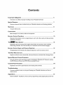
Contents
Important
Safeguards
5
Instructions on safety and proper handling of your Mitsubishi television
Special
Features
7
Distinctive features, items included with your Mitsubishi television and hookup guidelines
Shortcuts
8
A quick reference list
Connections
9
Basic hookups to an antenna, cable and components
Remote
Control
Functions
15
Features of the remote control, programming to work with other audio and video products,
explanation of buttons
Thel_H
° Menu
System
2I
Explanation of the on-screen menu system and the basic set-up menu screens including
Memorizing Channels, Set Clock and Day, AV Connection and On-Screen Language
Remote
Control
Input
and Channel
Selection
3I
Changing inputs and channels and setting the sleep timer with the remote control
The
Main
Menu
Screens
33
Explains the Parent Lock, Channel Edit, Advanced Features and Audio/Video
Special
Remote
Control
Settings Menus
Functions
49
How the remote works with other products including the Mitsubishi A/V Network, viewing
the PIP (Picture-in-Picture) and POP (Picture-outside-Picture)
Control
Panel
Functions
54
Explanation of the front panel buttons and the back panel terminals
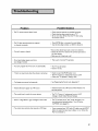
Troubleshooting
57
Common problems, notes on caring and cleaning your Mitsubishi television and how to
obtain service
Appendices
Diamond ShieldTM installation, remote control programming codes, bypassing the parent lock
6I
This
page is blank
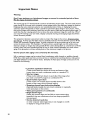
Please read all these instructions regarding your television set and retain for future
ence. Follow all warnings and instructions marked on the television.
refer-
I.
Read, Retain and Follow Instructions
Read all safety and operating instructionsbefore operating the appliance. Retain the safety and operating
instructionsfor future reference. Follow all operating and use instructions.
2.
Heed Warnings
Adhere to all warnings on the appliance and in the operating instructions.
3.
Cleaning
Unplug thisTV receiver from the wall outlet before cleaning. Do not use liquid or aerosol cleaners.Cleaners
can permanently damagethe cabinet or screen.Use a damp cloth for cleaning.
4. Attachments
and Equipment
Never add any attachments and/or equipment without approval of the manufacturer as such additions may
result in the risk of fire, electric shock or other personal injury.
5. Water and Moisture
Do not use thisTV receiver where contact with or immersionin water is possible. Do not use near bath
tubs, wash bowls, kitchen sinks,laundrytubs, swimming pools, etc.
6. Accessories
Do not place this TV receiver on an unstablecart, stand,tripod, bracket, or table. The TV receiver may fall,
causing serious injuryto a child or adult, and serious damage to the appliance. Use only
with a cart, stand,tripod, bracket, or table recommended by the manufacturer,or sold with
the TV receiver. Any mounting of the appliance should follow the manufacturer's instructions, and should use a mounting accessory recommended by the manufacturer.
An applianceand cart combination should be moved with care. Quick stops, excessive
force, and uneven surfaces may causethe applianceand cart combination to overturn.
7. Ventilation
Slots and openings in the cabinet are provided for ventilation and to ensure reliable operation of theTV
receiver and to protect it from overheating. Do not block these openings or allow them to be blocked by
placing the TV receiver on a bed, sofa,rug, or other similar surface. Nor should it be placed over a radiator
or heat register. If the TV receiver isto be placed in a rack or bookcase, ensure that there is adequate
ventilation and that the manufacturer's instructionshave been adhered to.
8.
Power Source
This TV receiver should be operated only from the type of power source indicatedon the marking label. If
you are not sure of the type of power supplied to your home, consult your appliance dealer or local power
company.
9.
Grounding or Polarization
This TV receiver isequipped with a polarized alternating current line plug having one blade wider than the
other. This plug will fit into the power outlet only one way. If you are unable to insertthe plug fully into the
outlet, try reversing the plug. If the plug should still fail to fit, contact your electrician to replace your
obsolete outlet Do not defeat the safety purpose of the polarized plug.
I 0. Power-Cord Protection
Power-supply cords should be routed so that they are not likely to be walked on or pinched by items placed
upon or against them, payingparticular attention to cords at plugs,convenience receptacles,and the point
where they exit from the appliance.
5
I I. Lightning
For added protection for thisTV receiver during a lightningstorm, or when it is left unattendedand unused
for long periods of time, unplug it from the wall outlet and disconnect the antenna or cable system. This will
prevent damageto theTV receiver due to lightning and power-line surges.
12. Power Lines
An outside antenna system should not be located in the vicinity of overhead power linesor other electric
light or power circuits, or where it can fail into such power lines or circuits. When installing an outside
antenna system, extreme care should be taken to keep from touching such power lines or circuits as contact
with them might be fatal.
13. Overloading
Do not overload wait outlets and extension cords as this can result in a risk of fire or electric shock.
14. Object and Liquid Entry
Never push objects of any kind into this TV receiver through openings as they may touch dangerous voltage
points or short-out parts that could result in a fire or electric shock. Never spill liquid of any kind on theTV
receiver.
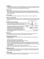
EXAMPLE
OF ANTENNA
GROUNDING
15. Outdoor Antenna
Grounding
If an outside antenna or cable system is connected to the TV receiver, be sure
the antenna or cable system is grounded so asto provide some
protection against voltage surges and built-up static charges.
Section 810 of the National Electrical Code,ANSI/NFPA
70-1984, provides informationwith respect to proper
grounding of the mast and supporting structure, grounding
of the lead in wire to an antenna discharge unlt, size of
grounding conductors, location of antennadischargeunit, connection to grounding electrodes, and requirements for the
grounding electrode.
LEADIN
{NEC
WIRE
SECTION
810-20)
GROUNDkNG
CONDUCTORS
=_POWE
R SERVIC
ELECTRODE
NEC -.
NATkONAL
ELECTRICAL
CODE
{NEC
ART
E GROUNDING
SYSTEM
250,
PART
H)
16. Servicing
Do not attempt to service this TV receiver yourself asopening or removing covers may expose you to
dangerous voltage or other hazards. Refer all servicing to qualified service personnel.
17. Damage
Requiring
Service
Unplug this TV receiver from the wall outlet and refer servicing to qualified service personnel under the
following conditions:
(a)When the power-supply cord or plug is damaged.
(b) If liquid has been spilled, or objects havefallen into the TV receiver.
(c) If the TV receiver has been exposed to rain or water.
(d) If the TV receiver does not operate normally by following the operating instructions, adjust only those
controls that are covered by the operating instructions as an improper adjustment of other controls may
result in damageand will often require extensive work by a qualified technician to restore theTV receiver to
its normal operation.
(e) If theTV receiver has been dropped or the cabinet has been damaged.
(f) When the TV receiver exhibits a distinct change in performance -- this indicates a need for service.
18. Replacement
Parts
When replacement parts are required, be sure the service technician has used replacement parts specified
by the manufacturer or have the same characteristics as the original part. Unauthorized substitutions may
result in fire, electric shock or other hazards.
19. Safety Check
Upon completion of anyservice or repairs to this TV receiver, ask the service technician to perform safety
checks to determine that the TV receiver is in safe operating condition.
0 ComponentVideo
Input
0 DiamondShield
TM- protective
VS-55705,VS-60705
0 IRIS
TM
- for the best picture
The following
video
players
andVS-70705
adjusts
models VS-50705,VS-55705,VS-60705
audio
DVD
screen shield for modelsVS-50705,
- sensor that automatically
0 Multibrand
from
Remote
Control
brightness
and contrast, for
andVS-70705
- use one remote
control
for many
components
items are included with your newTV:
Remote C0ntr_
2 AAA
batteries
m
II
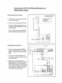
The connections shown in this book are general. Cable systems as well as individual audio andlor
video components can vary from those shown here. The first diagram show basic connections
to antenna or cable systems. After you have completed these, you can then connect any additional components (stereo, DVD, AV receiver, etc.).
IMPORTANT
To maximize your system for its best
performance, your dealer can help you
customize hookups and sell you any
additional connection accessories that
may be needed for your individual
equipment.
7
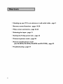
0 Hooking
0 Remote
up yourTV
control
0 Menu screen
0 Selecting
0 Setting
to an antenna
functions
summaries
or wall outlet
cable - page 9
- pages 19-20
- page 22-24
the input - page 3 I
theV-chip
0 Picture-in-picture
parent
mode
0 Picture-outside-picture
lock - page 33
- page 50
mode
(forVS-50705,VS-55705,VS-60705
0Troubleshooting-
page 57
andVS-70705)
-p_e52
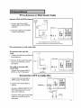
TV to Antenna
Separate
UHF
andVHF
orWall
Outlet
Cable
antennas
VHF Antenna
UHF A_ter _a
_3)
I, Connect the UHF andVHF
antenna leads to the UHF/VHF
combiner,
(Channel
Rat TwEn Le_d
14_9)
F_t TW_E_
L_ad 1
1
External
A_t_a
or Ca_
2, Press the combiner ontoANT-A
TV Back
Panel
i
o o
on theTV back panel.
00
O0
30_Ognrm t°
OPTIONAL"
ANT.A
o
Bacl;
@®@
®@@
o_, @o®
®
Sole
* there are different combiners for different wires.
Check with your dealer for the combiner style that you need.
Twin lead antenna
For antenna
leads
or wall outlet cable
with twin fiat
I, Connect the 300 ohm twin leads to
the transformer.
TV Back PaneI
fs Ohm
2. Push the 75 ohm side of the transformer onto ANT-A on theTV
back panel,
For cable or antenna
coaxial lead
,
o
2°°
.....L/
with
®
J
Connect the incoming cable to
ANT-A on the TV back panel,
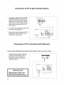
Connection
6
Twin Leaa
z
_o Ohm _ to 7_ Ohm out
Ma_r_i_g _r_ns_ormer
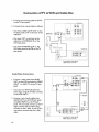
of TV to Cable
TV Back Pane]
I, Connect the incoming cable to
ANT-A on the TV back panel.
2, Connect two coaxial cables as
follows:
• One from CABLE LOOP-OUT on
theTV back panel to IN on the
back of the cable box,
• One from OUT on the back of the
cable box to ANT-B on theTV
back panel,
Box
Incoming Ca_
@
@@
@@
@@
%e
%o
Connection
ofTV
toVCR
and Cable
Box
I. Connect the incoming cable toANT-A
on theTV back panel.
TV Back Pa_e_
,i@
® ® @
® ® ®
2. Connect three coaxial cables as follows:
• One from CABLE LOOP-OUT on the
TV back panel to IN on the back of the
cable box.
C_BL_
ANTAL0_O0UT A_T B
®®
®o®
©
• One from OUT on the back of the
cable box to ANTENNA IN on the
VCR back panel.
• One from ANTENNA
OUT on the
VCR back panel to ANT-B on the TV
back panel.
V6R
Back
Pa_l
If your VCR has a video channel
ONIOFF
sw[tch_ set _tto OFF,
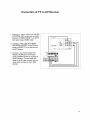
Audio Video Connections
TV B_ck
I. Connect a video cable fromVIDEO
o
®
OUT on theVCR back panel toVIDEO
INPUT I or INPUT 2 on theTV back
panel.
If you have a S-VHS VCR, follow the
same steps, using the S-Video terminals
on the VCR and TV.
2. Connect a set of audio cables from
AUDIO OUT on theVCR back panel
to AUDIO INPUT on the TV back
panel. The red cable connects to the R
(right) channel and the white cable
connects to the L (left). If yourVCR is
non-stereo, connect only the L (left)
cable.
,@
°&
®
RCA pin t
Attach
only
RCA
p[_ t pe
CabEe
cablo
typ_
VCR Back pa_e_
S-Video
_ype cable
If your VCR has a video channel
ON/OFF switch, set it to OFF,
10
Pane
e
Connection
ofTV
Wall
Cable
Antenna/Cable
Outlet
toVCR
and Antenna
or
Connections
If your VCR has a video channe{
ON/OFF switch, set it to OFF,
I, Connect the incoming cable toANT-A
on theTV back panel,
2, Connect two coaxial cables as follows:
• One from CABLE LOOP-OUT on the
TV back panel toANTENNA
IN on the
VCR back panel,
• One fromVCR back panelANTENNA
OUT to ANT-B on the TV back panel,
_T A _JTA_T
®®
i@ii@ @
®
Audio/Video
Connections
VCR Sack Panel
I. Connect a video cable fromVIDEO
OUT on theVCR back panel toVIDE@
INPUT I or INPUT 2 on theTV back
panel.
If your VCR has
a video channel
ON/OFF switch,
set it to OFF
If you have a S-VHS VCR, follow the
same steps, using the S-Video terminals
on the VCR and TV.
2. Connect a set of audio cables from
AUDIO OUT on theVCR back panel to
AUDIO INPUT on the TV back panel.
The red cable connects to the R (right)
channel and the white cable connects to
the L (left). If your VCR is non-stereo,
only connect the L (left) cable.
®
II
Connection
of TV to Stereo
I. Connect the audio cables from AUDIO
MONITOR OUTPUT on the TV back
Audio
System
Audio _y_Lern teat tetrn_na_
panel toTV IN orAUX IN terminals on
the back of the audio system. The red
cable connects to the R (right) channel
and the white cable connects to the L
(left) channel.
2. Turn off the TV'S speakers through the AV
Connection Menu (page 27).
TV Back
Pa_e_
of
o
3. Set the audio system's input to theTV or
AUX position to hear the TV's audio
through your stereo system.
_b
@@
®
Connection
To control
your Mitsubishi
of TV to the Active A/V Network
audio and/or video products
with one remote
Connect the A/V network cable from
ACTIVE A/V NETWORK on theTV
back panel to IN on the back of a
Mitsubishi component that has A/V
network terminal.
control
Mi_subishiCompone£treartermJnals
TV Back Panek
® @®
®®
IMPORTANT
@@@
ACTWE AN
N_TWORK
Check the Owner's
Guide of your
added Mitsubishi components
to
ensure the best possible connections.
12
®® ®
Connection
of TV to AV Receiver
I. Connect a video cable from VIDEO
MONITOR OUT on the back of the AV
Receiver toVIDEO INPUT I on theTV
TV _ack paneE
back panel using aVIDEO cable,
2, Connect a video cable fromVIDEO
MONITOR OUTPUT on the TV back
panel toVIDEOTV
the AV Receiver,
IN on the back of
3, Connect a set of audio cables from
AUDIO OUTPUT on the TV back
F_
F_JD-
®
AV RECEIVER
panel to AUDIOTV IN on the back of
theAV Receiver. The red cable connects to the R (right) channel and the
white cable connects to the L (left)
channel.
13
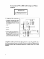
Connection
of TV to DVD
with
ComponentVideo
Outputs
IMPORTANT
For Digital Audio connections, see
the Owner's Guides of your DVD
Player and AV Receiver.
For ComponentVideo
Connections
I. Connect the ComponentVideo
cables
from VIDEO OUT on the back of the
TV Back Panel
I
0
DVD player to DVDVIDEO INPUT on
the TV back panel, matching the correct
components:
o
•
Y toY,
Cr to Cr,
Cb to Cb.
DVD Rear Terminal
2. Connect a set of audio cables from
AUDIO OUT on the back of the DVD
player to DVD AUDIO INPUT on the
TV back panel. The red cable connects
to the R (right) channel and the white
cable connects to the L (left) channel.
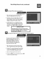
Warning:
Don't display the same stationary images on the screen for more than 15% of your total TV
viewing in one weelc Examples of stationary images are letterbox top/bottom bars from DVD disc or
other video sources, side bars when showing standard TV pictures on widescreen TV's, stock market
reports, video game patterns, station logs, web sites or stationary computer images. Such patterns can
unevenly age the picture tubes causing permanent damage to the TV. Please see page 58 for a detailed
explanation.
14
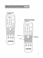
For Models VS-45605
and VS-50605
Additional
features
of Models
VS-50705,
VS-55705,VS-60705
and VS-70705
REC
STOP
PAUSE
light
GUIDE button
for DSSsystems
REW/REV
_
PLAY
FF/FWD
MITSUBISHI
REC
REW/REV
STOP
pLAy
PAUSE
FF/FWD
,_ MrrsuBISHI
15
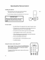
OperatingYour
Installing
Remote
Control
the batteries
tab in
I. Remove the back cover of the remote control by pushing the
the direction of the arrow and sliding off the cover.
2. Load the batteries, making sure the polarities(+) and (-) are correct.
IMPORTANT
When you replace the batteries in your remote
control, the remote
may return
to its initial
setting. You may need to set up your remote
again.
For best results
Be within 20 feet of the equipment when using the remote control.
Don't press two or more buttons at the same time, unless you are
specifically instructed to do so in this owner's guide.
Don't allow the remote control to get wet or become heated.
Avoid dropping the remote control on a hard surface.
When cleaning the remote control, don't use any harsh chemicals.
Use only a soft, slightly moistened cloth.
Don't mix new batteries with old ones.
Don't heat, take apart, or throw batteries into a fire.
Use alkaline batteries.
Using the remote
control
I_
with yourTV
C_LE/DB$
You can use your remote to control the TV, CABLE/DBS,VCR,
DVD or AUDIO. The remote has been preset to operate the
TV and other Mitsubishi products. It can be set to control
other audio/video equipment.
To operate the TV, the select switch at the top of the remote
should be set toTV.
16
ooo
O
O
VGR
O 0
O 0
DVD
0
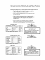
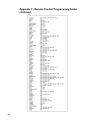
Remote
Control
Programming
of Other
the Remote
to Control
Audio
and Video
OtherAudio
andVideo
Products
Products:
Move the slide switch at the top of the remote to select the
audio or video product you want to control.
Press and hold the POWER button, so that it stays down when
you enter the code.
Enter the code for the equipment from the appropriate list,
exactly as stated. If there is more than one code number, start
with the first number. After setting the code, release the
POWER button.
Point the remote at the equipment and press the POWER
button. If it is on and turns off or is off and turns on, the
remote will control the equipment. If not, try the next number.
Cable box brand
General Instruments/
Jerrold
Oak
codeto enter:
111,119, 120, 121,122,
123, 124, 125, 126, 127
102, 137, 139
Pioneer
101, 116
Scientific Atlanta
111,112,113
Zenith
100, 117
To reset to default code, enter
Satellite
Satellite brand
codeto enter:
Dishnetwork
Hughes-DSS
RCA-DSS
175 "
173
176
Sony-DSS
Toshiba-DSS
Panasonic-DSS
Pdmestar
177
170
174
178
To reset
to
000
Receiver
If your
cable box
code is not
listed here,
please see
page 63
for a
complete
listing,
codes:
default code, enter 000
VCR
VCR
Tv.ll Aoo,o
CABLE/DeS
Cable Box codes:
DVD
I M PO RTA
NT
If you cannot turn the cable box ON
pressing POWER, try pressing the
CHANNEL
or the number buttons.
by
VCR
CABLE/DBS
OVD
If your
satellite
code is not
listed here
)lease see
page 63
for a
complete
listing,
codes:
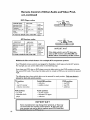
VCR
CABLE/DeS
VCR brand
codeto enter:
Mitsubishi
Hitachi
JVC
Philips/Magnavox
Panasonic
RCA
Sony
Toshiba
001,002
020, 043, 065
030, 054,059
043,044, 051
041,042, 043
020, 053, 065
048,049, 050
021,066
TO reset
to default
code,
enter
If your
VCR
code is not
listed here,
please see
page 64
for a
complete
listing.
000
I M PO RTA
NT
When set to TV, the PLAY, STOP, REW/
REV and the FF/FWD
keys will operate
theVCR
after theVCR
codes have been
chosen.
17
Remote
Control
of Other
Audio
and Video
Prod-
uct, continued
DVD
Player codes:
DVD/LDP brand
codeto enter:
Mitsubishi (DVD)
Mitsubishi (LDP)
Panasonic
003
016, 017
250
Pioneer DVD (LDP)
Sony
Toshiba
252 (016,017)
254
253
To reset to default code, enter 000
AV Receiver
Audio brand
VCR
CABLE/DaS
TV
If your
DVD code
is not
listed here,
please see
page 63
for a
complete
listing.
codes:
VCR
CABLE/DBS
TV
code_ en_r:
Mitsubishi AV receiver
010,011,012
013,014,015
200,208
209,214
205,207
222
Mitsubishi CD player
Kenwood
Onkyo
Pioneer
Sony
Yamaha
201,202
To reset to default code, enter 000
Additional
If your
Audio
code is not
listed here,
please see
page 63
for a
complete
listing.
slide switch feature:-for
multiple
DVD
IMPORTANT
If the slide switch is set toTV when you
enter an AV receiver code,VOLUME and
MUTE will be controlled by theAV receiver.
AJV component
systems
Your Mitsubishi remote control was designed for flexibility in both large and smallA/V systems.
For example, you can use the slide switch in the following way:
If you have twoVCR's, but no DVD player, move the slide switch to the DVD position and enter
the secondVCR code. Then when the slide switch is moved to DVD you can control the second
VCR.
The following chart shows which device can be entered for each position.
allowed for each slide switch position.
TV position:
• TV
• any A/V receiver
(volume, mute only)
VCR position:
• any VCR
• Mitsubishi DVD
player
/
I[J
DVD position:
• any DVD
• any VCR
• cable box
Audio position:
• any AV receiver
• Mitsubishi CD player
• cable box
Some manufacturers may change their products, or they may
use more than one remote
IM PORTANT
control system. If this is the case,
your remote_maY - not be able to operate yourVCR, Cable Box,
.................................
18
Cable/DBS position:
• cable box
• satellite receiver
Only one device is
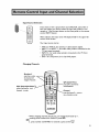
Remote
Control
Functions
Select switch
Selects which AN
wilt be controlled
Power
power
by the
or otherAN
remote
Numbers
--
To individually select
channels or enter
information into TV
SQV (SuperQuickView
Scan through a memorized
favorite channels
on and off for theTV
products
QV (QuickView)
Switches to last channel viewed
TM)
list of
SLEEP
Sets theTV to turn off
within 2 hours
INPUT
Selectsthe signal you will watch (Ant
A; Ant B; Input I, 2 or 3; DVD)
VIDEO
©0
Individually adjusts theVideo
settings
CHANNEL
AUDIO
View channels in increasing or
decreasing numerical order
Adualty adjusts
the Audio settings
VOLUME
Increases
or decreases
sound
MUTE
rurns
onoroffthesound
19
Remote
Control
Functions,
continued
ADJUST
Selects menu items.
Moves the PIP
on-screen location
ENTER
Use after selecting a
channel number or
menu item
LIGHT
For VS-50705,VS-55705,VS-60705
ooo
OOO
OOO
GO0
and VS-70705, press to light up
0
GUIDE
For
VS-S0705,VS-SS705,
VS-60705 andVS-70705.
_
satellite systems program
guides
J
the remote control
MENU
CANCEL
Clear SQV and some
menu entries
Displays on-screen menu
choices
HOME
Exit on-screen menus and
return to TV viewing
PIP or PIP/POP
Use to display,move,
resize or change a PIP
channel.ForVS-50705,
VS-55705,VS-60705 and
VS-70705 use to display,
resize or change a POP
channel
INFO
Displays an on-screen
summary
of currentTV
settings
N
OOOo
000
000
000
REC
Manually record
JJJ
_
STOP
To stop aVCR, DVD or
programs on your VCP_,_
PAUSE
_Temporarity
REW/REV
Rewind and reverse search for
theVCR. Skip reverse for CD.
Reverse scan for DVD
PLAY
PlaysaVCR,
20
FF/FWD
ast forward
stops a
VCR, DVD or CD or
freezes the PIP/POP
or forward
for aVCR. Skip forward
Fast play for a DVD
search
for a CD.
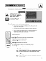
Your television has Mitsubishi's exclusive _l_on
screen information for menu choices and changes.
screen operating system, which provides on-
A highlighted icon isshown when
there is another men u level for your
choices. Pressingthe ENTER button
will displaythe men uoptions.
Make choices
or changesto a men
itemwhen you seea button.
u
The ViewPoint system includes the following special features:
The selected icon or button is highlighted with a yellow outline and
the text color will be yellow.
On-screen instructions provide complete menu choice information.
Some on-screenmenu optionsmust be setbeforeother optionsare
available. For example,"Set theTimer" will only be possible if
"ClockTime" and "Set Day" have been set.
0 0 @
O0
O0
O0
Making Selections:
_
IST•
or •
to select the menu item you want to change
ADJUST _' to move to the selection field
ADJUST • or • to change the settings
UST •
to move back to the menu item
• • _ ENTER E_:_to select an option, or start an automatic function
• CANCELC_:_ Lto clear a setting, or stop an automatic function
To exit the on-screen
MENU
menus:
Press the MENU key to move back one menu screen at a time
until you exit all the menus to return to television viewing
OR
Press HOME to exit all menus with one keystroke and return to
television viewing
21
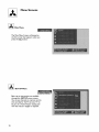
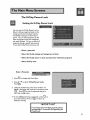
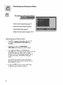
Menu
_Main
Screens
Menu
The Main Menu Screen will always be
the first screen that appears when you
press the _
button,
_
SETUPMenu
Basic set up instructions are available
through the SETUP menu screens.
You can put channels in memory, set the
time and day for the TV, set yourTV to
be part of a Home Theater setting and
view the menus in English or Spanish.
22
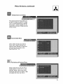
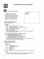
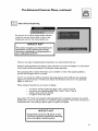
Menu
V-Chip
Screens,
continued
Parent Lock Menu
The optional, built-in V-chip allows you
to lock out programs, based on ratings.
The TV can be locked during a specific
time period. Locked programs can be
viewed after entering a 4 digit passcode
of your choice.
Channel
Edit Menu
Use to select the input you want to
watch, add or delete channels from
memory, name channels or inputs and
add your favorite channels to the
SuperQuickView TM list.
_
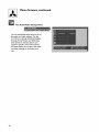
TheAdvanced
Features
Menu
These screens let you set yourTV to
display captions or text, turn on automatically, display a blue screen when
showing an input with no signal or align
(converge) the three main colors.
23
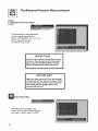
Menu
Screens,
The Audio/Video
Settings
continued
Menu
You can individually adjust some or all of
the audio and video settings. The five
A/V Memory settings: Standard, Daylight,
Evening, HomeTheater and DVD, have
been preset for the best picture and
sound for specific room environments.
AV Reset allows you to return the audio
and video settings to the factory presets.
24
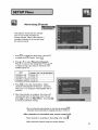
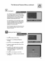
Memorizing
Channels
This selection memorizes the channels
yourTV can receive and skips the
unused channels. When memorization
is
complete, channels can be scanned using
the remote control.
MENU
l,
2.
Press_
to display the Main Menu. Use A0rV
to select the SETUP menu. Press ENTER
PressA0rV
to select Memorize
Channels,
Press I_ to move to the setting field. Press A0rV
to select the input you want to memorize. The
available inputs are:
INPUT
CHANNELS THAT CAN BE MEMORIZED
ANTENNA A AIR
2 through 69
ANTENNA B AIR
2 through
ANTENNA A CABLE
1 through 125
ANTENNA B CABLE
1 through 125
69
ENTER
3. Press _
to start the memorization. Added
channels will be labeled "In Memory". Channels
with poor or no reception will be labeled "Not in
memory".
4. After memorization is complete, the screen will
automatically return to the Setup menu. To exit,
HOME
press _
to return to Main Menu. Or, press
to return
to television viewing.
CANCEL
•You can stop the memorization at any time by pressing_.
Channels memorized before stopping will stay in memory.
After
channels are memorized,
your remote
control
will:
CHANNEL
•Select channels in ascending or descending order using _.
•Select individual channels using the number buttons.
25
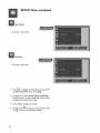
SETUP
Menu, continued
Set Clock:
To set the current
time.
Set Day:
To set the current day.
MENU
I.
Press_
to display the Main Menu. PressAorV
ENTER
to select the SETUP menu. Press _
.
2. PressAorV to select ClockTime
or Set Day.
Press • to move to the setting field. Press AorV
to select the correct time or day.
3. Press 4 after making your choice.
MENU
4. To exit, press _
to return to the previous menu
or _
to return to television viewing.
26
SETUP
Menu, continued
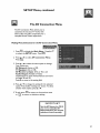
The AV Connection
Menu
The AV Connection Menu allows you to
customize the way your TV works with
other audio and video components, for a
complete Home Theater experience.
Making Menu Selections
for the AV Connection
Menu:
MENU
I.
Press_
to display the Main Menu. PressAOrV
ENTER
to select the SETUP menu. Press_.
2. PressAorV
ENTER
Press _.
to select AV Connection
Menu,
3. Press•0rVto
select the menu option to change.
Your choices are:
AV Network
(Active or Off),
TV Speakers (On or Off),
AV Receiver at Input I (Yes or No) and
Audio Output (Variable or Fixed).
(explanations for each of these features are found
on pages 28 and 29)
Pressl_ to move to the setting field.
4. Press •0rY
to change the setting for the selected
option. Press • after making your choice. To select
another menu option, press • or V.
MENU
5. To exit, press _
or
_
to
return
to return to the previous menu
to television viewing,
IMPORTANT
Set the AV Network to Off, if
you are not using theAV
Network System, for channel
selection to work correctly.
27
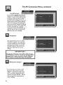
The AV Connection
The AV Network
For use with compatible Mitsubishi AV
Network or ACTIVEAV NetworkA/V
products. With anActiveAV Network
compatible VCR, some TV and VCR
functions can be simplified to just a few
presses of the remote control buttons.
With an AV Network compatibleVCR,
you can set the AV Network to Off and
still pass the remote control signal from
theTV to theVCR. For a detailed
explanation of Active AV Network, see
page 53. See the chart on page 30 to
determine the correct settings.
TV Speakers
This selection will turn on or off the
TV's built-in speakers. You may select
Off when sending the sound through a
separate stereo system or surround
sound AV receiver. See the chart on
page 30 to determine the correct
settings.
I M PO RTA NT
Changing theTV Speakers from OFF to ON will cause
theTV speakers to turn on. To prevent damaging theTV
speakers from a sudden increase in volume, make sure
theTV volume is turned down before choosing ON.
AV Receiver
at Input
I
Set toYes when you connect an AV
Receiver's video output to the TV's
INPUT I to prevent a possible "feedback" loop when changing the input
selection of the AV Receiver. See the
chart on page 30 to determine the
correct settings.
28
Menu,
continued
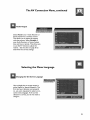
The AV Connection
Menu,
continued
Audio Output
Select Fixed if your Audio Receiver or
Stereo System has a remote control,
This allows you to adjust the volume
with that remote. Select Variable if
your Audio Receiver or Stereo System
does not have a remote, This allows you
to use the TV remote to adjust the
volume, See the chart on page 30 to
determine the correct settings.
Selecting
Changing
the Menu Language
the On-Screen
Language
Use to display the on-screen menus in
either English or Spanish (Espaffol). The
first time your television was powered
on, you were requested to select an onscreen menu language, If the current
selection is correct, you do not need to
change it.
29
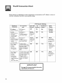
The AV Connection
Chart
Setting choices vary depending on which components are connected to the TV, Below is a chart of
common combinations and their recommended settings.
TV
Equipment
Connected
TV
used
AV Receiver
at Input I
Audio
Output
On
No
Fixed or
Variable
VCR Output to:
TV Input I.
TV Audio Outputs to:
stereo system inputs.
Active
(alsoset VCR
AV Network
to On)
Off
No
Variable
VCR Output to:
TV Input I.
TV Audio Outputs to:
stereo system inputs.
Active
(alsoset VCR
AV Network
to On)
Off
No
VCR Output to:
VCR with
• Active AV Networl_
controlled receiver
TV
Speakers
Setting
Off
VCR without
• Active AV Network
• non-remote
Active AV
Network
connection
Feature
TV input I.
or stereo system
VCR with
• Active AV Network
• remote controlled
receiver
the volume)
or stereo system
Home Theater AV
receiver with
• remote_
• any VCR
• and any other
AV equipment
Home Theater AV
receiver with
• remote,
• any VCR
• and any other
AV equipment
using a combination
of video
and S-Video cables.
TV Audio outputs
to the AV receiver inputs.
AV receiver monitor video
output to TV Input I.
All other AV equipment
outputs to AV receiver
inputs.
Off
TV Audio & Video outputs
Off
Off
Off
and S-Video ouput to
TV Inputs I and 2.
page
Yes
Fixed
volume)
All other AV equipment
outputs to AV receiver
inputs.
regarding
Fixed
(use the remote
for the AVreceiver
to control the
(use the remote
for the AV receiver
to control the
to the AV receiver inputs.
AV receiver monitor video
See
Yes
volume)
I M PO RTA NT
30
Fixed
(use the remote
for the AV receiver
or stereoto control
53 for
the AV
more
detailed
Network
information
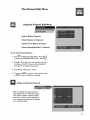
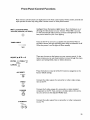
Input Source Selection
INPUT
If you want to view a picture from your DVD,VCR, camcorder or
laser disc player, you need to select the input the product is connected to. Use the input button on the front panel or the remote
control INPUT button.
After selection, the input name will display briefly in the upper left
corner of the screen,
Your input source can be:
• ANTA orANT B - for antenna or cable systems signals.
• INPUT I or INPUT 2 - for audio video product connected to the
TV back panel terminals.
• INPUT 3 - for audio video product connected to theTV front
panel terminals.
• DVD - for component (Y, Cr, Cb) DVD players.
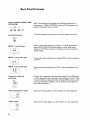
Changing
Channels
Numbers*
enter the n umber
the channel will
changein 4 seconds
-SQV (SuperQI
press to see memorized
channels , in order
QV (QuickView)
press QV to see the last
channel selected
Channel
pressthe channelb utton to
view channelsin order
*When changing channels directly, you can change them faster by: I.
entering three numbers; for channel 2, press 002
OR
ENTER
2. press number and ENTER; for channel 2, press 2 then O.
31
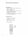
Remote
Setting
Control
for the Sleep Timer
the SleepTimer
SLEEP
Press(_)
on the remote control. TheTV will display the message:
Sleep:
030 Min.
[
SLEEP
With each press of _
the time increases in 30 minute intervals until
the maximum of 120 minutes is displayed.
SLEEP
Release (_
when the desired time is set.
SLEEP
To see how much time is left until the timer goes off, press _
The remaining time will display on-screen.
Canceling
the Sleep Timer
SLEEP
PressQ_)to
see the on-screen
display.
SLEEP
Press_
Sleep:
until you see the message:
OFF
[
The timer will be canceled.
0 0 0¢--_
Soo
©©
OOO
2
'
,._m'TaJBm
32
SLEEP
once.
TheV-Chip
Setting
Parent
theV-Chip
Lock
Parent
Lock
You can use theV-Chip Parent Lock to
Block or Allow programs based on the
ratings sent by the broadcast stations.
The default setting is to allow all programs. You can block programs by the
type of program and by the categories
you want blocked. Or you can block all
programs during a specific time period.
To use theV-Chip Parent lock, you will:
• Enter a passcode
• Select theV-chip
ratings
and categories
to block
• Select theV-chip
hours to lock and unlock for television
programs
• Select lock by time
Enter a Passcode
MENU
I.
Press_
2. PressA0rV
to display the Main Menu.
to select V-Chip
Parent Lock.
Press_;_.
3. Using the number keys, enter four numbers. To
delete a character and move back one space, press
CANCEL
ENTER
. Press _
to set the passcode and go to
theV-chip ratings menu.
MENU
4. To exit without entering a passcode, press _
HOME
go to the previous menu or_
to return to
television viewing.
to
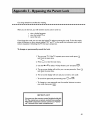
I M PO RT A NT
If you forget
seeAppendix
Parent Lock.
your four-digit passcode, please
3 : Procedure for Bypassing the
33
TheV-Chip
V-Chip
ratings
Parent
Lock, continued
and categories
Rating guidelines are provided by
broadcast stations. Most television
Ant-A 011 KTTV
Stereo SAP
TV-PG DSLV
programs and television movies can be
blocked byTV Rating and/or Individual
Categories. Movies that have been
shown at theaters or direct-to-video
movies use the Movie Rating system
only.
ForTelevision
Programs including
made-for-television
movies:
TV Ratings:
OFF
TV-Y
(youth)(individual categories do not apply)
TV-Y7
(youth, 7 years and up)
TV-G
(general audience)(individual categories do not apply)
TV-PG (parental guidance suggested)
TV-14
(14 years and up)
TV-MA (mature audience)
If you set theTV rating for TV-PG; TV-Y,TV-Y7,TV-G andTV-PG will be available.
TV-14 and TV-MA will be blocked.
Individual Categories (cannot use with TV-Y and TV-G):
FV - FantasyViolence (only applies to TV-Y7)
D - Sexual Dialogue (applies to TV-PG and TV- 14)
L - Adult Language (applies toTV-PG,TV- 14 and TV-MA)
S - Sexual Situations (applies to TV-PG,TV- 14 and TV-MA)
V - Violence (applies to TV-PG,TV- 14 and TV-MA)
Programs not rated: Programs that have not received a rating, such as sports, news
or other programs where a rating could not be given.
For Movies previously shown in
theaters or Direct-to-Video*:
Movie Rating:
Off
G
(general audience)
PG
(parental guidance suggested)
PG-13
(13 years and up)
R
(restricted)
NC-17
(18 years and up)
X
(adult)
If you set the lock for PG- 13; G, PG and PG- 13 will be available. R, N- 17 and X will be
blocked.
*Video tapes, laser discs or DVD's may not contain the specialV-Chip rating signals. If
this occurs, theV-Chip lock cannot be used to block these movies.
34
TheV-Chip
SelectingV-Chip
Parent
ratings
Lock, continued
and categories
I. After entering your passcode, pressA0rV
to
select the rating system you want to use.
,
Press • to move to the setting field. ForTV and
Movie Ratings, press A0rV
to select the programs rating you want to block. For Individual
Category, press • or • to allow or block.
3. To limitV-chip hours or to enable lock by time,
press •or•
to go to the V-Chip Hours/Lock by
Time menu. To exit, press _
to return to the
previous menu or _
to return to television
viewing.
IMPORTANT
Blocking programs with the V-chip will cause a
delay when programs change, or when you change
channels. The V-chip reviews each change to
ensure that it is"Allowed".
Selecting
theV-chip
hours to lock and unlock for television
programs
You may use the V-chip lock to block
programs during specific hours, and later
have it automatically turn off, so all
programming is displayed. If theV-chip
start and stop time are the same, or if
no start or stop time are specified, theVchip will be on 24 hours a day.
I. After entering your passcode, press•0r•
to
select V-Chip Hours/LockTime and press _.
2.
Press•0r•
to selectV-Chip StartTime. Press •
to move to the setting field. Press • or • select
the time. Press, after making your choice.
3. Select the V-Chip Stop Time the same way.
MENU
4. To exit, press _
to go to the previous menu or
to return to television viewing.
35
The V-Chip
Parent
Lock, continued
Select Lock byTime
You may lock all TV viewing for a set
time period, To view programs during
the locked time, enter your four-digit
passcode.
To lock theTV:
I. After entering your passcode, press • or • to
•
.
ENTER
select V-Chip Hours/LockTime and press<;:_.
2.
Press•0r•
to select Lock byTime. Press _ to
move to the setting field and use • or • to choose
On. Press • after making your choice.
3. Press•0r•
to select LockTime.
Press• after
making your choice. Select Unlock byTime the
same way.
MENU
HOME
4. To exit, press_
to go to the previous menu or
to return
to television viewing.
5. To view theTV during the locked time, enter your
passcode, when it is requested.
6. To reset the TV lock, turn off the TV.
IMPORTANT
I. If LockTime and UnlockTime are set to the same time,
the Parent Lock will be on 24 hours a day.
2. If LockTime is On and LockTime and UnlockTime
are not set, the Parent Lock will be on 24 hours a day.
36
The Channel
Edit Menu
Using the Channel
Edit Menu
• Add or Delete
Channels
• Select Names
for Channels
• Select Preset Names
for Inputs
• Select SuperQuickView
TM
Channels
To use edit channel features:
MENU
I. Press<_to
display the Main Menu. Press •0rV
ENTER
to select the CHANNEL EDIT menu. Press _
.
2. PressA or • to select the menu option you want
to change, Press I_ to move to the setting field,
Press • or • to change the selection,
3. Press • after making your choice.
MENU
4. ToHeoxit,press_
to return to the previous menu
or_
to return to television viewing,
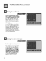
Adding
and Deleting
Channels
After all available channels have been
memorized with the "Memorize Channels" feature, weaker channels viewed
with AntA orAnt B can be added back
in or unwanted channels can be deleted,
on an individual basis.
37
The Channel
Selecting
Names
Edit Menu, continued
for Channels
You can personally name the channels
your TV receives on the INPUT Antenna
A or B, up to a maximum of four characters. After you enter a name, it will
appear on screen, next to the channel
number. SelectAntA or B for INPUT.
Select the memorized
want to name.
CHANNEL
you
At the NAME field, you can use letters
(A-Z), numbers (0-9) and/or symbols
(! .&' / :*-,
and blank). If you wantto
change your selection while in the
option field, use CANCEL to delete the
current character. This will move the
cursor one position back. If you press
CANCEL while at the first character, the
entire name will be deleted.
Selecting
Preset Names
for the Inputs
This feature allows you to keep track of
components that are connected to your
TV by selecting preset names for Inputs
I, 2, or 3. The new name will appear
on the screen display when the inputs
are selected. There are 15 names that
you can choose from,they are: VCR I ;
VCR2; DVD; LASER; SAT (satellite);
CABLE; CAM (camcorder); GAME;
VHS; S-VHS; DTV; WEB (Internet
set-top-box); MAIN; AUX; and
SURV (surveillance or security).
38
The Channel
Selecting
SuperQuickView
Edit Menu, continued
Channels
TM
SuperQuickView
allows you to put
together a list of your favorite channels.
You can quickly look through the list
using the SQV button.
TM
Once you've added a channel to the
SQV memory, the letters "SQV" appear
under the channel number any time the
channel number is displayed, even if you
tune to the channel using another
method.
I
IMPORTANT
SQV memorizes
ANTA
orANT
channels from
B only.
adding the SQV channels directly
l,
2
with the remote
control
Use the CHANNEL button or number buttons to select the
channel you want to add to the list.
Press and hold the SQV button for about 3 seconds. The
letters "SQV" will appear under the channel number, indicating
that the channel has been added to SuperQuickView
memory.
TM
removing
SQV channels with the remote
L
control
Press the SQV button repeatedly to select the channel to be
removed from the list.
2. While the channel number and SQV indicators are still
displayed on the screen, press the CANCEL button.
3. When the SQV indicator disappears, the channel has been
canceled from the SuperQuickView list. If you wait until the
channel and SQV indicators disappear automatically, then the
CANCEL button will not remove the channel from the list.
39
The Advanced
Features
The Advanced
Features
• Select Closed Captioning,
• Select theTimer
• SelectVideo
Option,
Menu
page 4 I
page 42
Mute, page 42
• Adjust the Convergence,
Using the Advanced
Menu
Features
pages 43-44
Menu:
MENU
I. Press_
to display the Main Menu. Press Ai,orV
to select the ADVANCED
FEATURES menu.
ENTER
Press_.
2. Press Aorv to select the ADVANCED
FEATURES menu options you want to change.
3. For CAPTIONS,TIMER or CONVERGENCE,
press E_R tO go tO the selected menu. Then pressAor V
to select the option you want to set or change.
Press • to move to the setting field and press AorV
to change the setting. Press4 after making your
choice.
For Video Mute, press • to move to the setting
field and press A orVto change the setting. Press •
after making your choice.
MENU
To exit, press _
or _
40
to
return
to return to the previous menu
television viewing.
to
The Advanced
Features
Menu, continued
Select Closed Captioning
You can turn on or off the closed caption decoder
screen.You can also choose black or gray as the
background color for the closed caption area.
IMPORTANT
The content of captions are determined
by the
broadcaster.
If your captions show strange
characters, misspellings,
or odd grammar, it is
not a malfunction
of theTV.
There are two types of captioning that broadcasters can send: standard and text.
Standard captioning follows the dialogue of the characters on-screen and displays in a small section
of the screen when the broadcaster is sending the closed captioning.
Text captioning often contains information such as weather or news, Text captioning blocks a
portion of the program that is on-screen.
Your TV can decode four different standard captioning signals and four different text captioning
signals from each TV station. However, each station may broadcast only one or two captioning
signals, or none at all.
When setting the decoder, you can choose to display:
one of four standard captioning signals ( CC I, CC2, CC3, CC4)
one of four text captioning signals (Text I,Text 2, Text 3, Text 4)
captions when mute (On if mute)
no captions when mute (Off)
If you select"On if mute" the standard captioning signal (CC I) will appear whenever you use the
MUTE button. If you set the decoder to a"standard" caption setting or "On if mute" and tune to a
broadcaster that is not sending a caption signal, no captions will appear.
IMPORTANT
A large black or gray box will appear on your
TV screen, if you have selected text captioning,
and no text signal is being broadcast.
41
The Advanced
_
Select theTimer
Features
Menu,continued
Option
This special feature will automatically:
tune to a memorized channel on
ANT A, ANT B, INPUT I, 2 or 3, or the
DVD at a specific time and;
turn theTV on, if it is off.
I M P O RT A NT
TheTV's
clock must be set before you can set
the timer. If you haven't set the clock and/or
day, you will see the SETUP Menu with Set
Time selected instead of theTimer
menu.
I M PO RTA NT
When the timer turns theTV on, the message
"Press a key forTV to stay on" is shown. If you
don't press a button on the remote
control or
front panel within 5 minutes, theTV will
automatically
turn off.
Select Video
Mute
Video Mute lets you display a blue
screen when no signal is being received
from Input I, Input 2, Input 3 or DVD.
42
The Advanced
Features
Menu, continued
Convergence
Your Mitsubishi Projection TV has three picture
tubes with large diameter lenses which are aligned
to project light beams on the screen. Each picture
tube projects only one color: red, green or blue.
During production, your television was carefully
adjusted to properly align these colors.
As a special feature, you have the ability to adjust
the color convergence, should you think that the
red and/or blue light beams are out of alignment.
The green beam acts as a fixed reference for
aligning the red and blue beams.
Static Convergence aligns the whole screen at one
time. Advanced convergence aligns 64 individual
adjustment positions
Adjusting
the Static Convergence:
MENU
I. Press_
to display the Main Menu.
2. PressA0rV
to select Advanced
Features.
PressE_:_ R •
ENTER
3. PressA0rV
to select Convergence.
Press_.
4. PressAorV
to select either Red or Blue Conver-
gence. Press _.
5. PressA ,Vor_l
to align the color you selected
with the fixed green lines. The vertical and horizontal lines will merge into a single white cross
when aligned correctly.
VIDEO
Press(_
MENU
to switch between red and blue.
,
AU
7. PressG:_ to exit, or _
Convergence.
IO
to proceed toAdvanced
43
The Advanced
Advanced
Features
Menu, continued
Convergence
Before you can adjust the Advanced Convergence, you must
adjust the Static Convergence
for
both Red and Blue.
I.
PressA •V or • to move the flashing bracket to a
position that needs adjustment. Press ENTER_
to
stop the flashing.
Z
Press A ••
or • to move the red or blue line. A
position is converged when all three lines combine
to make a white line.
|mmmmmmmm
Immmmmmmm
mmm mmm
|mmmlmmmm
|mmmmmmmm
Immmmmmm
ENTER
3. PressO
when aligned and the bracket will flash
again. Repeat this process to align other positions.
I M PO RTA
NT
VIDEO
4.
Press _
to alternate between red and blue.
MENU
5. To exit, press _
or _
to
to return to the previous menu
return
Resetting
television viewing,
to
the Factory
Defaults
MENU
L
Press _2_ to display the Main Menu.
Z
PressA or •
to select Advanced
Features.
Press_;_.
ENTER
.
PressA0r•
to select Convergence.
Press _.
PressA or • to select Reset Factory Default,
ENTER
_
Press_.
The message Convergence reset
completed" will display when the defaults are
reset.
MENU
5. To exit, press _
H
or_
44
E
to
return
to return to the previous menu
....
to
television
viewing.
There are more than 64 line
intersections.
However, the
bracket will only stop on the 64
adjustment
positions.
P
Audio/Video
Adjusting
Settings
Menu
the Audio and Video Settings
TheTV has fiveAV audio video memories. The memories are: Standard,
Daylight, Evening, Home Theater
and DVD. You can adjust the settings of
each memory using the menus or you
may adjust the settings of the currently
used memory using the remote control,
AV Reset will return the setting of the
currently selected memory to the
original factory presets,
The memory for each input (Antenna A
or B, Input I, 2, 3 or DVD) is preset to
Standard. You can select and adjust a
different memory for each of the TV
inputs, which will be recalled each time
that input is selected.
VIDEO
Using the AUDIO
AUDIO
orVIDEO
button
on the remote
VIDEO
control
AUDIO
DO0
300_
ADJUST
I, Press _
or _
repeatedly until the desired
setting displays at the bottom of the screen.
2. Press'0r'
to change the setting. In 5 seconds the
display will disappear.
MENU
45
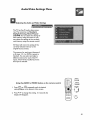
Audio/Video
AV Memory
I.
Settings
Menu,
Menu Settings
Press INPUT on the remote to select the desired
input to change.
MENU
2, Press _
to display the Main Menu.
3. Press •0rVto
SETTINGS.
4.
Press•orV
select AUDIO/VIDEO
ENTER
Press_:_ .
to select AV Memory.
5. Press • to move to the setting field. Press • or •
to select theAV Memory to change. Press41after
making your choice.
6. PressA0rrto
selec_JDIO
SETTINGS orVIDEO
SETTINGS. Press _
to display the individual
settings. Press • or, to change the setting.
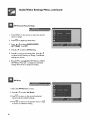
AV Reset
I. Select the AVMemoryto
2. Press•Or•
reset.
to select AV Reset.
ENTER
3. Press _
to return to the currently
memory_ factory default settings.
selected
MENU
4. Press _
to
46
return
to return to the previous menu or_
to television viewing.
continued
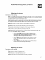
Audio/Video
Adjusting
Descriptions
Settings
Menu,
continued
the picture
of video settings
IRIS is the Intelligent Room Illumination (light) Sensor. When IRIS is on, yourTV will automatically
adjust the picture contrast and brightness for the best picture based on your room lighting. Included
on modelsVS-50705,VS-55705,VS-60705
andVS-70705.
TM
Contrast provides a scale that controls the level of white-to-black in the picture. Low contrast will
show a variety of shades in the darker images on the screen. High contrast will show the screen's
dark images more uniformly black and make the colors on the screen seem more vibrant.
Brightness
provides a scale that controls the overall brightness of the picture.
Sharpness
provides a scale that adjusts the detail and clarity of the picture.
Tint
Color
provides a scale that adjusts the proportion
of red to green in the picture.
provides a scale that determines the intensity of the color.
ColorTemp
(Color temperature)
choices are "Low 6500K," "High:'
allows you to set how the TV will display white images. Your
or "Medium,"
With the Low 6500K setting, white images on-screen will have a
warm cast to them. This setting represents the 6500°K industry
standard. This adjustment is an average and can vary due to ambient
room lighting,video scene brightness and the TV's age.
With the High setting, white images on-screen will have a cool cast
to them. This setting may provide the most realistic picture under
bright lighting.
With the Medium setting, white images on-screen will be balanced
between the Low (warm) and High (cool) settings.
Adjusting
Descriptions
the sound
of audio settings
Bass enhances or reduces low frequency sound.
Treble
enhances or reduces high frequency sound
Balance adjusts the level of sound between the left and right speakers.
47
Audio/Video
Adjusting
Settings
Menu,
continued
the sound, continued
Surround creates simulated stereo and surround effects. You can set this setting to"Off,"
late" or "Surround."
Select:
"Simu-
Offwhen you do not want to use any surround effects. Set the
surround setting to"OFF" when using an A/V receiver with Dolby _
Pro Logic Surround, or Dolby Digital Surround.
Simulate when you are watching a non-stereo program. Your TV
will create a simulated stereo effect by using theTV's speakers.
Surround when you are watching a stereo program. Your TV's
internal speakers will create a simulated surround effect, making the
sound seem to extend around and behind you.
Listen to determines how yourTV will receive a broadcast audio signal and play back the sound
that you hear. You can set this function to "Stereo"
"S.A.P." or "Mono"
Stereo is the default setting. With this setting, the TV will play
stereo broadcasts in stereo and mono broadcasts in mono. Stereo
broadcasts will display the word "Stereo" when you tune to that
channel.
S.A.P. is an additional monaural soundtrack that you can't hear
during normal TV viewing. The S.A.R signal might be related to the
program you are watching, such as a soundtrack in a foreign language, or it might be unrelated such as a weather report. If the S.A.R
signal is broadcast, the letters "SAP" will appear on-screen when you
tune to that channel. Choose "Listen to: SAP" to hear the S.A.R
signal.
Mono will reduce background noise and should be used if you are
receiving a weak stereo audio signal. The sound will be only in mono
even if the program you are watching is in stereo.
Level Sound automatically equalizes the volume level of programs that contain significant sound
level differences from one segment to another, for example; regular programming to commercials. To
receive the best audio fidelity for music programs, you may want to turn this setting to Off.
"Dolby;' "AC-3"' "Pro Logic" and the double-D symbol are trademarks of Dotby Laboratories Licensing Corporation.
Copyright 1992 Dolby Laboratories, Inc. All rights reserved.
48
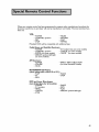
Whenyourremotecontrolhasbeenprogrammed
to operateothermanufacturer's
productsthe
functionsit performson eachlayerwill varybymanufacturer
andmodel.Themostcommonfunctionsare:
YCl_
•
•
•
•
POWER
CHANNEL
REC
STOP
up/down
•
•
•
•
PAUSE
REW/REV
PLAY
FF/FWD
Mitsubishi VCRs will be compatible with additional keys
Cable Boxes and Satellite Receivers:
• POWER
• 0-9 number keys (on some models)
• CHANNEL up/down
• CANCEL (on some models)
• ENTER (on some models)
• GUIDE
(on some models)
• ARROW up/down/left/right
(on some models)
AV Receivers:
• POWER
• VOLUME
• MUTE
• DIRECT INPUT SELECTION
(on some Mitsubishi models)
MITSUBISHI
CD Players
(when using audio code 010 or 01 I):
• PLAY
• PAUSE
• FF
• STOP
• REW
DVD and Laser Disc players
(not all functions for all models):
• POWER
• 0-9 numbers
• MENU
• CANCEL
• STOP
•
•
•
•
PAUSE
REW
pLAy
ARROW
up/down/left/right
49
Special Remote
Picture
in Picture
Control
Functions,
continued
Mode
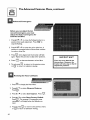
For modelsVS-45605 andVS-50605,you can display a PIP (Picture-in-Picture) in one of two different
sizes. For modelsVS-50705,VS-55705,VS-60705
orVS-70705 you can display a PIP in one of five
sizes or you can display up to three POP's (Picture-outside-Picture).
The PIP or POP can be shown
in all inputs, except DVD.
The INPUT
source
To see the PIP you need to select an input source. If the only input you have connected is ANT A,
then both the main picture and PIP will both be from ANTA.
If you have connected other video products, you may be able to view the main picture and PIP
images from different input sources. Please review the chart to see the possible combinations:
PIP:
Main
Picture:
ANTA
ANT B
INPUT 1
INPUT 2
INPUT3
DVD
ANT A
X
X
X
X
n/a
ANT B
X
X
X
X
n/a
INPUT 1
X
X
X
X
n/a
iNPUT 2
X
X
X
X
n/a
iNPUT 3
X
X
X
X
n/a
ADJUST
PIP
PIP/POP
PIP SIZE
PAUSE
EXCH
VS-45605 andVS-50605
50
AdditionalFeaturefor:
VS-50705,VS-55705,VS-60705
andVS-70705
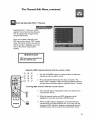
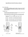
Special Remote
Selecting
Control
the INPUT
Functions,
continued
source
PIP
Ant.A O11 KTTV
Stereo SAP
TV.F_3 DLSV
SQV
pip A OOE
I. To view a PiP image, press[_.
PIP INPUT
2. To see the available PIP inputs, press [--1
repeatedly. The input
name will be displayed on screen for about five seconds. Turn on the
equipment connected to INPUT I, 2 or 3 if you select one of these
inputs as the PIP input source.
Changing
ANT A
the PIP channel when PIP input source is
P_P
I. Press []_).
PIPCH
2. Press
_
to show a different
channel on the PIR
PiP
3. Cancel the PIP by pressing F--I
Changing
again.
the PIP size
For models VS-45605 orVS-50605 you have a choice of two different PIP sizes.
For models VS-50705,VS-55705,VS-60705 or VS-70705 you have a choice of five
PIP sizes.
Ant-A011
S'ter_ S_
TV_PG DLSV
SQV
pip A O2g
p_p S_ZE
To change the PIP size, press[]_).
Each press will change the size.
Ant'A O11 KTTV
Stereo SAp
pip A 008
_._oLsv
Moving the PIP image
ADJUST
Press_
to move the PIP image anywhere on the screen.
VCR
Freezing
the PIP image
°A_°_] I _'_,_D,o
Verify that select switch is in the TV position.
PAUSE
While viewing a PIP channel, press (_
to freeze the image.
PAUSE
Press _
again to return to a live picture.
51
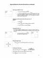
Remote Control
continued
exchanging
of the PIP (Picture-in-Picture),
the PIP and main picture image
EXCH
_:_',;_'
_
_
Press _
to exchange the PIP and main picture image.
IMPORTANT
Wd_e
ma_ p_ttre _ from ANT B
and0hePIPisfrom ANTA, ablankPIP
Displaying one or three POP (Picture-Outside-Picture)
for modelsVS-50705,VS-55705,VS-60705
andVS-70705
PIP/POP
I.
images
PIP/POP
Press (_.
You will see a PIP image, Press
again to see one POP image. The POP channel will be
different than the main TV picture channel.
If the POP image is from ANT-A, you can use PIP CH to
change the POP image.
TV
PICTURE
POP
PIP/POP
2. Press _
again to display three POP's. When the POP
image is from ANTA, each image will be a different
channel. Only one POP image will be live action. The
others will be frozen.
POP 1
TV
PICTURE
POP 2
POP 3
PIP/POP
4. To return to a PIP image, press [_l
52
again.
Ant-A 011 KTTV
Stereo SAP
TV-PG DLSV
SQV
PiP A 008
Remote
Control
of the Active AV Network
The AV Network is a special feature that makes it easier to use your television and other Mitsubishi
A/V components together. When you connect the AV Network, you can point the remote control at
the television, and it will pass the remote control command to other components. You will gain even
more benefits if you have a Mitsubishi VCR equipped for the Active AV Network and a Mitsubishi
DVD player.
Before you begin, be sure you have:
Made the correct AV Network connections. Refer to "'Connection of TV to the
Active AV Network"in the Connections section.
Connected yourVCR to INPUT- I of yourTV and/or connected your DVD to
DVD INPUT.
Set your VCR's remote control settings toVCR.
Turned yourVCR video mute setting on.
Turned the Active AV Network feature in the VCR and the TV's menu to ACTIVE.
Using the PLAY key on the remote,
after selectingVCR
with the slide switch:
Active AV Network will turn yourVCR on and begin playing a tape (if tape is
inside).
Active AV Network will turn your TV on and switch it to INPUT- I.
When you turn your TV off, your VCR will turn off, unless it is playing or recording.
Displaying theVCR
menu
When you set the remote toVCR and then press MENU:
• Active AV Network will turn on yourVCR if it is off and display theVCR's menu
(this function may not work with some older MitsubishiVCR's).
• Active AV Network will turn on yourTV if it is off and switch it to INPUT- I.
Using the PLAY key on the remote,
after selecting
DVD with the slide switch:
Your remote must be programmed to operate Mitsubishi DVD players.
Active AV Network will turn on yourTV and switch it to DVD INPUT.
If your DVD player is in range of the remote and has a disc inside, the DVD
will turn on and the disc will begin playing.
when"
"
_po_
I[ yo_emo_o_ol_EL_o_
IMPORTANT
I
53
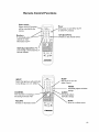
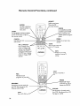
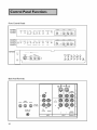
FrontControl Panels
VS-45605,
VS-50605
• ..............
,
o
O
T_J
_1 •
4_usl
vs.50705,
r
o o
.........
VS-55705,/@
VS-60705[
C...........
U
@ @ @ @ @
b-
E_I_
..........
@
@
_IE_U
CA_OE_
o
,
@@,_,
(_VOL(_
.....
...... .......
@o
_U
...........
............
VS-70705
_NPUT-3
TINE_
S-VIDEO
•
V_DEQ
(MQNO)
L AUDIQ
"5%'% 5 5 5
R
CANCEL
AOJUST
CHANNEL
OOOOOOO
M£NU
ENTER
•
•
•
Back Panel Terminals
I
0
0
V
TUNER/
MONITOR
0
I
D
E
O
A
L
CrO
CABLE
ANT-A
LOOP-OUT
ANT
0
L
U
(MONO)
-B
D
I
R
O
0
ACTIVE AN
NETWORK
®
54
0
0
DVD
(YCrCb)
AUDIO
1
2
INPUT
INPUT
FIXED]
VARIABLE
OUTPUT
VOL
•
POWER
Front Panel Control
Functions
Many remote control buttons are duplicated on the front control panel. Power, volume, channel and
input operate the same way, using either remote control or front panel buttons.
IRIS
TM
(modelsVS-50705,
VS-55705,VS-60705,
VS-70705)
Intelligent Room Illumination (light) Sensor. Turn this feature on or
off using the video button on your remote. When IRIS is on, your
TV will automatically adjust picture contrast and brightness for the
best picture based on your room lighting.
If you set theTV to turn on at a specific time (seeTimer Menu in
the Menu section) the light will blink green when the television is off.
When the power is on, the light will shine steadily.
TIMER LIGHT
orO
TIMER
ADJUST,
•
ENTER,
_'V
_
or '_
MENU,
MENU
_._
ENTER
AN
CANCEL
These are the same as the buttons on your remote control, In the
menu screens, you can use these buttons to move through the menu
options and setting fields, make or delete selections.
_E_u
RESET
_._
CANCEL
Press this button to reset all of theA/V
factory default settings,
AJV RESET
AN
memory categories to the
RESET
@
Connect the video output of a camcorder
nent to theTV.
VIDEO
or other video compo-
VIDEO
S-VIDEO
S-VbDEO
@
Connect the S-video output of a camcorder or other standard
component to theTV. If you connect a S-video cable to this terminal, you cannot use the adjacentVIDEO input.
Connect the audio output from a camcorder or other component
to your TV,
L-AUDIO-R
(MONO)
L AUDIO
R
55
Back Panel Terminals
Antenna (ANT-A,
OUT, ANT-B)
CABLE
LOOP OUT
ANT-A
ANT
CABLE
LOOP-
B
ANT A and ANT-B receive signals from VHF/UHF antennas or a
cable system. CABLE LOOP OUT sends the ANT-A signal out to
another component (such as aVCR).
Connects Mitsubishi product that have an A/V network terminal,
Active AJV Network
ACTIVE A/V
NETWORK
®
INPUT
I and 2 S-Video
@@
INPUT
I and 2 video input
Either of these video terminals connect to a S-video signal from a
SuperVHS (S-VHS) VCR, laser disc player or other audio video
device to the TV. If you connect to S-Video, you cannot connect to
standard video.
Connect the video output from a standardVCR or other equipment
to the TV.
®®
INPUT
I and 2 audio input
Connect the audio output from aVCR or other equipment to the
TV.
Component video and
audio input
Connect the component video and audio signals from a DVD player
or other equipment with component video outputs to theTV. If you
connect the three component video terminals (DVD) and you wish
to use the TV's built in speakers, use the adjacent audio inputs for
your audio connection.
Video
Sends the TV video signal to an A/V receiver or other equipment,
Audio
56
monitor/tuner
output
output
Sends the TV's audio signal to an A/V receiver or other equipment.
Problem
Possible
Solution
The TV remote control doesn't work
• Check that the batteries are installed correctly.
• Check that the select switch is set to "TV".
• Be no more than 20 feet from the TV when using
the remote control.
The TV takes several seconds to respond
to channel commands
• Press ENTER after a command to avoid delays.
• Use the three digit number, i.e. 002 for channel 2.
You can't access a channel
• Be sure the channel you want to view is in memory.
• Check that the TV is tuned to the correct input source
for that channel.
• Make sure the V-chip lock is off.
On-screen displays appear each time
you change a function
• This is part of normal TV operation.
You can't program the TV to turn on automatically
• The TV may be locked.
• Clock is not set..
There's no sound even when the volume is turned up
• Check to see if the MUTE button is on.
• The TV's "Listen to:" setting may be set to S.A.P.
• Check that "TV Speakers" setting is ON.
You forget your parent lock passcode
• See "Bypassing the Parent Lock, Appendix 3".
Antenna-B doesn't appear as a PIP source
• Antenna B cannot be a PIP source when Antenna A is
the main picture.
The sound doesn't match the screen picture
• The TV's "Listen to:" setting may be set to S.A.P.
Change in Audio Video Memory Settings.
There is a large black or gray rectangle on the screen
• The TV has been set to "text" mode, but there is no
text information being broadcast. Turn Off in the
CAPTION menu (page 4 I).
• You cannot see a picture when you play a VCR tape
If you connected your VCR with A/V cables, use the INPUT
button to select the Input source (Input 1,2, or 3) that the
VCR is connected to.
57
Important
Notes
Warning:
Don't leave stationary or letterboxed
Mix the types of pictures shown.
images on-screen
for extended
periods of time.
The normal use of aTV should include a mixture of television picture types. The most used pictures
types should fill the screen with constantly moving images rather than stationary images or patterns.
Displaying the same stationary patterns over extended periods of time, or displaying the same
stationary pattern frequently can leave a subtle but permanent ghost image in your picture. Note
that moving images with stationary black bars can also leave a subtle but permanent ghost image. To
avoid this, mix your viewing pattern; do not show the same stationary image for more than 15% of
your totaITV viewing in any one week. Display constantly moving and changing images that fill the
screen whenever possible.
This projection television uses picture tubes to project the image to the screen. All picture tubes
age with use. As they age,their light output is gradually reduced. Normal television pictures fill the
screen with constantly changing images. In these conditions, the picture tubes age at an even rate
across the entire screen. This maintains aTV picture that is evenly bright over the whole screen.
Stationary images or images that only partially fill the screen (leaving blank or colored bars to fill the
screen), when used over extended periods of time or when viewed repeatedly, can cause uneven
aging of the phosphors and leave subtle ghosts of the stationary images in the picture.
Uneven
picture tube aging is not covered
by the warranty.
Still or stationary images may be received from broadcasters, cable channels or satellite channels,
DVD discs, video tapes, laser discs, on-line services or web/internet searching devices, video games
and digital television tuner/converter
boxes. Examples of these types of image can be, but are not
limited to the following:
• Letterbox top/bottom
black bars
(These are the black bars shown at the top and bottom of the
screen when you watch a widescreen movie on a standardTV)
• Side bar images
(These are the solid bars shown on each side of the image when
you watch a normaITV program on a widescreenTV)
• Stock-market
report bars
(These are the row of stock prices normally shown at the
bottom of the screen during a financial report)
• Shopping channel Iogos and pricing displays
(Especially bright displays that are shown constantly or repeatedly
in the same place on the screen)
• Video game patterns or scoreboards
• Bright station Iogos
(Subtle, low-contrast Iogos are less likely to cause uneven aging,
especially if they are translucent and are not always projected in
the same spot)
• On-line (internet)
web sites
or other computer style images that are not changed or are left
on display for long periods of time
58
Important
Notes, continued
Warning:
If you place speakers next to the TV, make sure they are magnetically shielded. Ordinary speakers
will cause distortion in the picture due to their strong magnets. This distortion, however, will not
harm the picture tubes.
For maximum enjoyment and safe operation of your Mitsubishi TV, please read IMPORTANT SAFEGUARDS, pages 3 and 4 of your Owners Guide, very carefully and apply them properly
Cleaning:
Normally, light dusting with a non-scratching
duster will keep your TV clean.
If you want to wipe down your TV, turn it off and unplug it.Then, wipe it gently with a soft cloth
slightly moistened with water. You can add a few drops of mild liquid detergent to the water for oily
dirt.
DO NOT
allow liquid to enter theTV through the ventilation slots.
DO NOT
use strong or abrasive cleaners.
DO NOT
use spray liquids or cleaners directly on the TV's surface.
DO NOT
scrub or rub the TV harshly.Wipe gently.
59
If Service
is Required
If you are unable to correct a problem with your TV, consult your Mitsubishi dealer or Mitsubishi
Authorized Warranty Service Center.
DO NOT
adjust any controls not described in this owner's guide.
130 NOT
remove the protective
back cover of this unit.
If you see the following display on your screen, you should not change any settings. This is a special
display used by the factory.
If any settings are changed, your warranty may be void.
NOTE:
"Series Settings" are included for reference only and will vary from those shown below.
If this display appears, make sure that all of the on/off settings are the same as the illustration below
and then turn the TV off. If any of the settings are different from the illustration below, turn the TV
off and consult your Mitsubishi dealer or Mitsubishi Authorized Warranty Service Center.
Initial
E2RESET
Power Res
When Mute
Direct key mode
VS-70705
V-CHIP
Series Setting:
Series Setting:
60
Off
On
Off
On
.......
VZ7 ........
Thecustom-fittedDiamondShieldis anextraprotectionfor yourtelevisionscreen.It hasa subtle
tint thatenhances
picturecontrast.It canberemovedor installed,
according
to yourpreference.
ForVS-45605
andVS-50605,
the DiamondShieldisanoptionthatcanbepurchased
separately
from
yourMitsubishi
dealer.
Formodelsthathavethe DiamondShieldalreadyinstalled,
youcanremovethe shieldifyouprefer.
Formodelswherethe DiamondShieldis includedin aseparatepackage,
youcaneasilyinstallthe
shield.Carefullyremovethe masking
paperonthe DiamondShield.Thisis thecoated,scratchresistantsidewhichshouldfaceoutwardfromtheTV.Thenremovetheplasticsheetfromthe other
sideofthe DiamondShield.Thisisthe uncoatedsidewhichshouldfaceintotheTV.
Wearcottonglovesto preventfingerprintson the DiamondShield.
Installation
or removal
• For all models
of the Diamond
Shield:
exceptVS-70705:
remove the top molding clip with a small fiat head screwdriver,
pressed into the opening at the upper corner (Illustration I)
remove the bottom molding clip, with a small fiat head screwdriver, pressed into opening at the bottom corner
after loosening corners, pull gently to remove
to install, insert shield by sliding it into the right side channel
(Illustration 3)
gently press on the shield sides to bow the screen towards you
insert the left side channel
reinstall the molding clips. Do not force.
to remove, remove the top and bottom molding clips and gently
press on the shield sides to bow the screen towards you. It will
pop out of the top panel (Illustration 3)
reinstall the molding clips. Do not force.
VS-45605_VS-50605_VS-50705_VS-E
;705,VS-60705
I
IMPORTANT
Store your Diamond Shield TM
carefully so that the shield does no1
become scratched.
Illustration
1
Illustration
2
61
Appendix
I- Diamond
Shield
TM,
continued
• ForVS-70705:
remove the right side molding clip with a small fiat head screwdriver,
pressed into the opening between molding andTV side panel (Illustration 2)
remove the left side molding clip, with a small flat head screwdriver,
pressed into opening between molding and TV side panel
after loosening corners, pull gently to remove
- to install, insert shield by sliding it into the bottom channel (Illustration 4)
gently press on the shield top to bow the screen towards you
insert into top channel
reinstall the molding clips. Do not force.
to remove, gently press on the shield top to bow the screen
towards you. It will pop out of the side panel. (Illustration 4)
VS-45605.VS-50605,VS-50705,VS-55705,VS-60705
Illustration
62
3
VS-70705
Illustration
4
Cable
AV Receiver
Mitsubishi
Admiral
Aiwa
Denon
Fisher
Gerrard
Harman Kardon
Jeneen
JVC
Kenwood
Magnavox
Marantz
Mclintosh
Nakamichi
Onkyo
Optimus
Panasonic
Philips
Pioneer
Quasar
RCA
Sansui
Sharp
Sony
Sound-sigh
TEAK
Technics
Victor
Yamaha
011,012,
013,014,
220
225,226
234,235,236
204
213
215
223
232,233
200,208
227,228
224
216
206,217
209,214
203,227,
231,230
219,218,221
223
205,207
219,218,221
203,205,
227,231,230
203,211,239
234,237
222
238
212,213,
210,211
221,218,219
232,233
201,202
010
ABC
Archer
Cableview
Citizen
Color Voice
Comtronics
Curtis
Diamond
Eagle
Eastern
GO Brand
GE
Gemini
General Instrument/Jerrold
Hamlin
Hitachi
Macem
Magnavox
Memorex
Movietime
Oak
Pacesonic
Paragon
Phillips
Pioneer
Pulsar
Puser
RCA
Realistic
Regal
Regency
Rembrandt
DVD
Mitsubishi
Denon
003
250
Ferguson
GE
JVC
Normande
Panasenic
251
251
257
251
250
Philips/Magnavox
Pioneer
ROA/Proscan
Saba
Sony
Thomson
Toshiba
Yamaha
Zenith
258
252
251,256
251
254
251
253
250
259
Satellite Receiver
Echostar
G,E,
Hitachi
Hughes
Panasonic
175
176
173,181
173
174
Philips
Primes_r
RCA
Sony
Toshiba
Uniden
171,172
178
176,179,180
177
170
171,172
Samsang
Satellite
Scientific Atlanta
Signature
SL Mark
Sprucer
Starcom
Stargate
Teleview
Texscan
Tocem
Toshiba
Unika
United Artists
United Cable
Universal
Videoway
Viewstar
Zenith
124
132,125
105,132
122,105
128,129,130,106,107
128,129,130,106,107
112,113
124,132,125
129
134
132,105
111,112,113
122,143
111,119,124,125,126,127,120,121,122,123
140,141,142,145,118,112
103,124
103,104,105,108
128,129,130,106,107,133,138
130
132
139,137,102
109,110,114
117
128,129,130,106,107,133,138
101,116
105,132
132
115
132
112,118,140,141,142,145
134
137,132,105,138
105
100
111,112,113
119,124,125,126,127,120,121
122,111
105,101
105,110
119,124,125,126,127,120,121,122,111
132,105
101,105
144
135,136
104
132,125
139,137,102
119,124,125,126,127,120,121,122,111
122,132
106
129,130
117,100
63
Appendix
continued
2 - Remote
Control
Programming
VCR
64
Mitsubishi
Admiral
Aiwa
Akai
001,060, 067, 068, 061,062,
055
047, 052
049, 034, 035, 036
Audio Dynamic
Bell & Howell
Broksonic
Canon
Citizen
059,
025,
040,
043,
026
Craig
Curtis Mathes
Daewoo
DBX
Dimensia
Emerson
Fisher
Funai
GE
GO Video
Goldstar
Hitachi
Instant Replay
Jensen
JVC
Kenwood
LXt
Magnavox
Marantz
Marta
Memorex
MGA
Minolta
Multitech
NEC
Olympic
Optimus
Orion
Panasonic
Penney
Pentax
Philco
Philips
Pioneer
Proscan
Quasar
Radio Shack
RCA
Realistic
Samsung
Sansui
Sanyo
Scott
Sears
Shaintom
Sharp
Signature 2000
Singer
Sony
SV2O00
Sylvania
Symphonic
Tashiro
025, 049, 026
065, 044, 047
063, 021,044, 079
059, 030, 031
065
023, 038, 039, 040,
025, 028, 029, 027
047, 046, 040
057, 065, 044
057, 069, 070, 071
026
043, 065, 020
044, 043
059
059, 030, 031,054,
059, 030, 026, 031
047, 026, 020, 027,
051,043, 044
059, 030, 031
026
044, 029
058, 060, 067, 068,
020, 065
067, 047, 024
059, 030, 031,054
044, 043
048, 041,055, 026
046, 040
043, 044, 041,042
044, 020, 065, 025,
020, 031,065
051,044, 047, 043,
051,043, 044
043
065, 020, 043, 044,
041,042, 043, 044
053, 044, 025, 056,
053, 065, 020, 043,
044, 025, 056, 029,
057, 022, 024, 053
059, 046, 040, 072
025, 029
021,022, 024, 029,
025, 026, 027, 028
037
055, 056
047, 055
037
048, 049, 050, 073,
047
051,043, 044, 047
047
026
Tatung
TEAC
Technics
Teknika
Toshiba
Totevision
Vector Research
Wards
Yamaha
Zenith
059, 030, 031
059, 030, 047, 031
032,041,042,043,
044
044, 047
021,066
026
031
055, 056, 029, 064, 026
025, 059, 030, 031
064
002
031
033
046
045
045,046,062,
063,
076,077
028, 025, 029
061,062
059, 030, 031
046,040
051,066,
021,022
029, 060, 047
044,049, 051,066,
060, 047
021,022
058, 060, 067, 068, 046,040
020
074,075
Codes
Cut alongdottedlineandfile afterreading.
Afteryousetthe lock,youwill needthe secretcodein orderto:
• viewa lockedprogram,
• viewthe IockedTV,
or
• cancelthe lock.
If youforgetthe code,youcanviewthe lockedTVwithoutenteringthecode.Todo this,simply
pressthe buttonsonyour remotelabeled"QV" and "9" at the same time whenever your secret
code is requested.
Unlocking theTV this way is temporary.
To change or permanently
cancel the lock:
I. Turn on your TV. If theTV requests your secret code, press
and(_) at the same time.
MENU
2. Press Q
to view the main menu.
ENTER
3. Use the • or • to select"V-Chip
Parent
Lock" and press _
.
4. The on-screen display will ask for your current passcode. Press (_)
and _) at the same time.
5. The on-screen display will now ask you to enter a new code:
MENU
• To cancel the passcode
permanently,
press Q
H
E
or _.
• To change to a new passcode, use the number buttons to enter a
new code, then press ENTER
IMPORTANT
You must use the remote
control included with this
TV. You cannot use a remote
control from another
Mitsubishi component
and you cannot use "Univer_
sar' remotes
from other manufacturers.
65
This page is blank
66
Index
A
D
Active AV Network
28, 53
Adding and deleting channels 37
Adjustments
picture 47
sound 47-48
Day, setting 26
Diamond Shield TM Installation
DVD player codes
61-62
18, 63
F
Advanced features menu 23, 40-44
Audio output 29
Audio/video memory settings 45, 46
Audio/video settings menu 24, 45-46
AV connection menu 27-29
AV receiver
at Input I 28
codes 18, 63
Front panel buttons
55
H
Home theater connections chart 30
Hookup, Choosing a 7
I
Important
B
Back panel terminals, 56
Buttons, remote control
Safeguards 5-6
L
19-20
Language,menu 29
C
I_1
Cable Box codes 17, 63
Channel edit menu 23, 37-39
Cleaning 59
Clock, setting 26
Closed captioning
Connections to
Active
A/V
Memorizing
Menu
4/
Network
antenna 9
AV receiver
Main menu 22
channels menu 25
Advanced Features 23, 40-44
Audio output 29
Audio/Video Settings 24
AV network 28
AV connection 27-30
12
13
cable box 9
AV receiver at Input I 28
Channel edit 23, 37-39
component DVD 14
StereoAudio System 12
VCR and cable box 10
VCR andAntenna or Cable
wall outlet cable 9
II
Memorizing Channels 25
Parent Lock 23, 33-36
Set Clock 25
Convergence
Advanced 44
Resetting factory defaults
Static 43
Closed captioning 4 /
Language 29
Main 22
44
Set Day 26
Setup 22, 25-27
TV speakers 28
Viewpoint Menu System 21
Sound, adjusting 47-48
SQV(SuperQuickView
Name
channels 38
inputs 38
Timer
automatic television turn on 42
Parent Lock
sleep 32
Troubleshooting
57
TV speakers 28
bypassing 65
menu 23, 33-36
passcode setting 33
setting 33
time lock 36
U
V-chip ratings and categories 34-35
Picture, adjusting 45
PIP (Picture-in-Picture) 50
changing channel 5 I
changing the size 5 I
exchanging with main picture 52
freezing 5 /
Input source 50, 51
moving 5 I
POP (Picture-outside-Picture)
52
16
AV receiver codes 18, 63
buttons 19-20
cable box codes
17, 63
Complete list of codes 63-64
controlling other Audio
Video Product 17-18
DVD player codes 18, 63
installing batteries 16
menu operation 21
satellite receiver code 17, 63
special functions 49
VCR codes 17, 64
Remote Control Functions, special
Remote control operation 16
S
Satellite receiver codes
Service, required 60
Setup menu 22, 25-27
Shortcuts 8
SleepTimer 32
Special Features 7
19,39
T
P
Remote Control
TM)
17, 63
49
UnpackingYour TV
7
Y
Viewpoint Menu System 2 /
VCR codes 17, 64
Video mute 42
MITSUBISHI
PROJECTION
TELEVISION
LIMITEDWARRANTY
MITSUBISHI DIGITAL ELECTRONICSAMERICA, INC. ("MDEA") warrants to the original purchaser of this television that if purchased from an authorized
MITSUBISHI Audio/Video Dealer, should it prove defective by reason of improper workmanship and/or material:
a. Parts. The lenticular (i.e. front picture) screen and/or the DiamondShieldT_ is warranted against defects in materials and workmanship for a period of 30
days.A{I other parts are warranted for a period of one year from the date of the original purchase at retail.We will repair or rep{ace,at our option, any
defective part without charge for the part. Parts used for replacement are warranted for the remainder of the original warranty period.
b. Labor. For 30 days after the original purchase at retail, we will repair or replace, at our option, the lendcular screen if it proves defective. For all other
parts, we will provide the labor for a warranty repair by an authorized MITSUBISHI service center without charge for one year from the date or original
purchase at retail.
c. Notice.To
obtain warranty service,you must notify an authorized MITSUBISHI service center of any defect within the applicablewarranty time period.
I.TO OBTAIN WARRANTY SERVICE:
a. Contact your nearest authorized MITSUBISHI service center whose name andaddress can be obtained from your MITSUBISHI dealer or by writing or
calling MDEA at the address and telephone number provided below.
b.Warranty service will be provided in your home or, if required, at an authorized service shop, provided that your television is located within the geographic
territory customarily covered by an authorized MITSUBISHI service center. If not, you must either deliver your television to an authorized service location
at your own expense, or pay for any travel and/or transportation costs the service center may charge to and from your home.Actual service labor will be
provided without charge.
c. Proof of purchase date from an authorized MITSUBISHI dealer is required when requesting warranty service. Present your sales receipt or other
document which establishes proof and date of purchase.THE RETURN OFTHE OWNER REGISTRATION CARD IS NOTA CONDITION OFWARRANTY COVERAGE. However, please return the Owner Registration Card so that we can contact you should a question of safety arise which could affect
you.
2.THIS WARRANTY DOES NOT COVER damage caused by:modification, alteration, repair or service of the product by anyone other than an authorized
MITSUBISHI service center; physicalabuse to, or misuse of, the product;operation in a manner contrary to the instructions which accompany the product,
including uneven picture tube aging and imprinted imageson the viewing screen; freight damage;or any damagecaused by acts of God such as lightning or
fluctuation in electrical power.This warranty also excludes all costs arising from instal{ation, adjustment of user controls,external antenna systems, service of
products purchased or serviced outside the U.S.A.,initial technical adjustments (set-up) and user-required maintenance. Consult the operating instructions
furnished with the product for information regarding user controls.
3.ANY EXPRESSWARRANTY NOT PROVIDED HEREIN, AND ANY REMEDYWHICH, BUT FORTHIS PROVISION, MIGHTARISE BY IMPLICATION
OR OPERATION OF LAW, IS HEREBY EXCLUDED AND DISCLAIMED. THE IMPLIEDWARRANTIES OF MERCHANTABILITY AND OF FITNESSFOR
ANY PARTICULAR PURPOSEARE EXPRESSLYUMITEDTO ATERM OF ONEYEAR.
4. UNDER NO CIRCUMSTANCES SHALL MCEA BE LIABLETO PURCHASER ORANY OTHER PERSON FORANY INCIDENTAL, SPECIAL OR
CONSEQUENTIAL DAMAGES,WHETHERARISING OUT OF BREACH OFWARRANTY, BREACH OF CONTRACT, OR OTHERWISE.
5. Some states do not allow limitations on how long an impliedwarranty lasts,or the exclusion or limitation of incidental,special, or consequentialdamages,
so the above limitations or exclusions may not apply to you.
6.This warranty gives you specific legal rights, and you may also have other rights which vary from state to state.
7. BEFORE REQUESTING SERVICE,pleasereview the instruction booklet to insure proper installation and correct customer control adjustment. If the
problem persists,contact your nearest MITSUBISHI Dealer for name(s) of authorized MITSUBISHI Service Center(s). If you are unable to obtain this
information, pleasecall B00-332-2119, or write us at the address below.
MITSUBISHI DIGITAL
9351 Jeronimo Road
Irvine, CA 92618-1904
RETAIN
THIS PORTION
DEALER
NAME
STREET
ADDRESS
CITY
PHONE(
ELECTRONICS
FOR YOUR
AMERICA,
RECORDS
STATE
)
INC.
MITSUBISHI
I SERIAL
NO.
MODEL
NO.
ZIP
PURCHASE
/
DATE
MO
/
DAY
YR
MITSUBISHI
MITSUBISHI
DIGITAL
9351 Jeronimo Road
Irvine, CA 92618-1904
ELECTRONICS
@ 1999 Mitsubishi Digital Electronics America, Inc.
871 D249A20
AMERICA,
INC.
Printed in U.S.A