1
,_I_
[::1mG mT A L
MITSUBISHI
ELECTRIC
TELEVmSmoNS,_
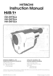
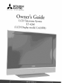
LCD
Television
System
(LCD Display model: L423FR)
RISK QF ELECTRIC SHOCK
TO REDUCE THE RISK OF ELECTRIC
DQ NOT OPEN 1
SHOCK, DO NOT REMOVE CO
V
ER OR BACK.
NO USER SERVICEABLE" PARTS INSIDE.
_
-_ TO QUALIFIED
REFER SER V ICING
SERVICE PERSONNEL.
The lightning flash with arrowhead symbol within an equilateral triangle is intended to alert the
user of"the presence of'uninsulated
"dangerous voltage" within the product's enclosure that may be
suf'f'icient magnitude
to constitute
a risk of'electric
shock.
The exclamation point within an equilateral triangle is intended to alert the user to the presence of"
important operating and maintenance
(servicing) instructions
in the literature accompanying
the
product.
Note: This equipment has been tested and fi_und to comply with the limits fi>ra Class B digital device, pursuant to part 15
of the FCC Rules. These limits are designed to provide reasonable protection against harmf\fl interference in a residential
installation. This equipment generates, uses and can radiate radio frequency energy and, if not installed and used in
accordance with the instructions, may cause harmful interference to radio communications. However, there is no guarantee
that interference will not occur in a particular installation. If this equipment does cause harmful interference to radio or
television reception, which can be determined by turning the equipment offand on, the user is encouraged to try m correct
the interf)rence by one or more of the f'ollowing measures:
* Reorient
or relocate the receiving
" Increase
the separation
between
antenna.
the equipment
and the receiver.
* Connect the equipment into an outlet on a circuit different f'rom that to which the receiver is connected.
° Consuh the dealer or an experienced radio/TV
Product
Name:
Liquid
Crystal
High
technichn
Definition
TV
for help.
system
WARNING:
TO REDUCE THE RISK OF FIRE OR ELECTRIC
OR MOISTURE.
SHOCK, DO NOT EXPOSE THIS PRODUCT
TO RAIN
CAUTION:
TO PREVENT ELECTRIC SHOCK, MATCH WIDE BLADE OF PLUG TO WIDE SLOT, FULLY INSERT.
NOTE TO CHTV SYSTEM
INSTALLER:
THIS REMINDER IS PROVIDED TO CALL THE CATV SYSTEM INSTALLER'S ATTENTION
TO ARTICLE
820-40 OF THE NEC THAT PROVIDES GUIDELINES
FOR THE PROPER GROUNDING
AND, IN PARTICULAR,
SPECIFIES THAT THE CABLE GROUND SHALL BE CONNECTED
TO THE GROUNDING
SYSTEM OF THE
BUILDING, AS CLOSE TO THE POINT OF CABLE ENTRY AS PRACTICAL.
_
LAMP(S)
ACCORDING
INSIDE THIS PRODUCT CONTAIN MERC[JRY
TO LOCAL, STATE OR FEDERAL LAWS.
AND MUST BE RECYCLED
OR DISPOSED
OF
Important
Sa_guards
..................................................................................................................
Cleaning Your LCD Television System ........................................................................................
Chapter
I
Thank
Chapter
Chapter
Chapter
Chapter
Television
4
7
System OvervDw
You ...................................................................................................................................
9
Unpacking Your New TV System ................................................................................................
Special Features ...........................................................................................................................
Side Control Panel and Card Reader ............................................................................................
10
11
12
Side Panel Input/Output
13
2
%levision
..............................................................................................................
System Setup
Attaching HD-6000 to 42" LCD Display ...................................................................................
Set-Back Configuration
Setup .....................................................................................................
Connecting a Computer ......................................................................................................
Stand Alone Conf`iguration Setup ................................................................................................
Connecting a Computer ......................................................................................................
Wall Mount Conf`iguration Setup ................................................................................................
Connecting a Computer ......................................................................................................
15
16
20
21
22
23
27
3
Connections
Connecting a VCR to the LCD Side Panel ..................................................................................
Connecting an Audio Receiver ....................................................................................................
Connecting a DVD Player or Other S-Video Device ...................................................................
Connecting a Satellite ReceNer/Cable Box ...................................................................................
Connecting a Computer ..............................................................................................................
How Connections Af_ct the PIP and POP .................................................................................
29
30
31
32
33
34
4
Remote
Control
Functions
Overview of`the TV Layer Buttons ..............................................................................................
Operation ....................................................................................................................................
Sleep Timer .................................................................................................................................
Use With Other A/V Products ....................................................................................................
37
38
39
40
Operation
42
of PIP, POP & Double Window
.................................................................................
5
?_4enu Screen Operations
The ViewPoint _ Menu System ....................................................................................................
MAIN Menu .............................................................................................................................
SETUP Menu ..............................................................................................................................
ADVANCED
FEATURES Menu ...............................................................................................
45
47
48
50
AUDIO/VIDEO
52
Chapter 6
SETTINGS
Menu ...........................................................................................
_pecialFeatures
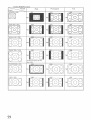
Available On-Screen
Format Sizes .........................................................................................................
57
Operation of` PIP and POP and Double Window ........................................................................
Appendix A: HD Input Connection Compatibility .....................................................................
Appendix B: Supported PC Resolutions .......................................................................................
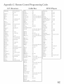
Appendix C: Remote Control Programming Codes .....................................................................
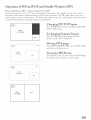
Appendix D: Media Command TM and Media Card Playback .....................................................
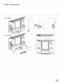
Cable Management ......................................................................................................................
Index ............................................................................................................................................
60
61
61
62
62
66
67
Troubleshooting ...........................................................................................................................
\Warranty ......................................................................................................................................
69
74
IMPORTANT
Please
read the following
Always fbllow all warnings
1.
SAFEGUARDS
safeguards
carefully
and instructions
before
marked
using
this product
Read, Retain and FoHowAH
Instructions
Read all safety and operating instructions befbre operating the product.
f'or fhture reference. Fbllow all operating and use instructions.
.
and retain
for future
reference.
on the product.
Retain
the safety and operating
instructions
Heed Warnings
Adhere to all warnings on the product and in the operating instructions.
Cleaning
Unplug the product from the wall outlet befbre cleaning. Do not use liquid, abrasive, or aerosol cleaners.
can permanently damage the cabinet and screen. Use a lightly dampened cloth fbr cleaning.
3_
.
Attachments
and
Equipment
Never add any attachments
and/or equipment without approval of the manuf:acturer
the risk of'fire, electric shock or other personal irl}ury.
Water
5_
Cleaners
as such additions
may result in
and Moisture
Do not use the product where contact with or immersion
kitchen sinks, laundry tubs, swimming pools, etc.
in water is possible.
Do not use near bath tubs, wash bowls,
Accessories
6_
Do not place the product on an unstable cart, stand, tripod, or table. The product may f:all, causing
serious injury to a child or aduk and serious damage to the product. Use only with a cart, stand,
tripod, bracket, or table recommended
by the manuf_cturer,
or sold with the product. Any mounting
of'the product should fbllow the manuf:acturer's instructions,
and should use UL 1678 listed wall
mounting brackets suitable f'or the weight and mounting surf:ace used.
The product and cart combination
should be moved with care. Quick stops, excessive force, and
uneven surf:aces may cause the product and cart combination
m overturn.
7.
Ventilation
Slots and openings in the cabinet are provided for ventilation and to ensure reliable operation of the product and to
protect it f?om overhearing.
Do not block these openings or allow them to be obstructed by placing the product on
a bed, sof_, rug, or other similar surf:ace. Nor should it be placed over a radiator or heat register. If" the product is
to be placed in a rack or bookcase,
have been adhered to.
Power
8_
ensure that there is adequate
ventilation
and that the manuf:acturer's
instructions
Source
This product should be operated only from the type of power source indicated on the marking label. If you are not
sure of the type of power supplied to your home, consult your appliance dealer or local power company. The socketoutlet shall be installed near the equipment and shall be easily accessible.
.
10.
Grounding
or Polarization
This product is equipped with a three-wire grounding-type
plug, a plug having a third grounding pin. This plug
will only fit into a grounding-type
power outlet. This is a safety feature. If'you are unable to insert the plug flflly
into the outlet, contact your electrician to replace your obsolete outlet. Do not defeat the safety purpose of'the
grounding-type
plug.
Power-
Cord
Protection
Powe>supply
cords should be routed so that they are not likely to be walked on or pinched by items placed upon or
against them, paying particular attention to cords at plugs, convenience receptacles, and the point where they exit
f'rom the product.
11. Lightning
For added protection fbr this product during a lightning storm, or when it is left unattended
periods of time, unplug it f\_om the wall outlet and disconnect the antenna or cable system.
damage to the product due to lightning and power-line surges.
and unused fbr long
This will prevent
IMPORTANT
12. Power
An outside antenna
power circuits,
extreme
13.
SAFEGUARDS,
continued
Lines
system should not be located
in the vicinity
care should be taken to keep f¥om touching
Overloading
Do not overload wall outlets,
of fire or electric shock.
When
power lines or other electric,
installing
through
openings
parts that could result in tire or electric shock.
light or
an outside antenna
such power lines or cimuits as contact
extension cords or integral convenience
14. Object and Liquid Entry
Never push o[_}ects of any kind into this product
shor>out
of overhead
or where it can f2dl into such power lines or circuits.
receptacles
system,
with them might be f:atal.
as this can result in a risk
as they may touch dangerous
voltage points or
Never spill liquid o£ any kind on or into the product.
15. Outdoor
Antenna
Grounding
If an outside antenna or cable system is connected to the product, be sure the antenna
as to provide some protection against voltage surges and built-up static charges.
or cable system is grounded
Section 810 of the National Electric Code, ANSI/NFPA
No. 70, provides
infbrmation
with respect to proper grounding o_'the mast and supporting structure,
grounding of"the lead in wire to an antenna discharge unit, size o£ grounding
conductors,
location
and requirements
16.
o_"antenna
discharge
fbr the grounding
unit, connection
to grounding
EXAMPLEOF ANTENNA GROUNDING
electrodes,
electrode.
(NEC SECTrON 8r0 20)
Servicing
Do not attempt to service this product yourself as opening or removing covers may
expose you to dangerous voltage or other hazards. Re}_r all servicing to qualified
service personnel.
_
NEC
17. Damage
Requiring
Unplug the product
conditions:
so
Service
£rom the wall outlet and refer servicing
to qualified
service personnel
NATIONAL ELECTRICALCODE
POWEF{SERVICEGfiOLINDING
_LECTlqODESYSTEM
(NECART 250 PARTH)
under the fbllowing
(a) When the power-supply cord or plug is damaged.
(b) If liquid has been spilled, or o[t}ects have fidlen into the product.
(c) If the product has been exposed to rain or water.
(d) If the product does not operate normally by following the operating instructions,
a@lst only those controls that
are covered by the operating instructions as an improper ac{}ustment of other controls may result in damage and will
of'ten require extensive work by a qualified technician to restore the product to its normal operation.
(e) If the product has been dropped or the cabinet has been damaged. The liquid crystal display used in this product
is made of glass. It can break if dropped. Do not come in contact with the liquid crystals or glass in case the LCD
display breaks.
(£) When
the product
exhibits
a distinct
18. Replacement
Parts
When replacement parts are required,
change in perf'ormance
be sure the service technician
manuf:acturer or have the same characteristics
electric shock or other hazards.
19. Safety Check
Upon completion
determine
20.
- this indicates
as the original
of any service or repair to the product,
that the product is in saf_ operating
part.
a need fbr service.
has used replacement
Unauthorized
ask the service technician
parts specified
substitutions
to perfbrm
by the
may result in fire,
saf?ty checks to
condition.
Heat
The product should be situated away f'rom heat sources such as radiators, heat registers, stoves, or other products
(including amplifiers) that produce heat. Do not place this product in an enclosed place (bookcase or wail) without
proper ventilation.
Do not block the vents or openings
on this product.
IMPORTANT
21.
SAFEGUARDS,
continued
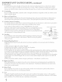
Transport!Handling
(a) Be sure to use another person to lift or carry this product. It is recommended
that the product
people holding it with both of their hands -- one hand on each side of the product.
(b) Use caution when transporting
the product. Be sure that items such as belt buckles,
zippers do not scratch or rub the screen or cabinet.
(c) Do not grip the cu>outs
shown in Diagram
1. These cu>outs
watches,
be carried
by two
shirt buttons,
and
are not handles.
Diagram 1.
DO NOT USE AS HANDLES
22.
LCD
Monitor
This monitor uses a technology composed of over 2.9 million thin film transistors.
It is common to find a f_w
cobred (non-active) "dots" on the screen. Do not be alarmed. This is a result of'the manuf:acturing process found in
all panels. Your picture performance
will not be affbcted.
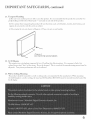
23. Wall or Ceiling Mounting
The product should be mounted to a wall or ceiling only as recommended
by the manuf_cturer. When mounting
the LCD display to a wall or ceiling, the stand and Se>Back Box (HD-6000)
must be removed from the back of the
LCD display.
6
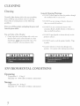
Cleaning
General
" DO
Normally, light dusting with a dry, non-scratching
duster will keep you,: product clean. If cleaning
beyond this is needed, please use the following
guidelines:
First,
turn
offthe
from
the power
product
and unplug
the power
cord
moistel_ed
with water.
dry; sob, non-abrasive
Dry
cloth.
NOT
product's
° DO
NOT
product.
CONDITIONS
Operating
Temperature:
Humidity:
5 - 35 deg C
30 - 80% relative
(without
condensation"
(without
condensation
Storage
Temperature:
Humidity:
20 - 50 deg C
10 - 90% relative
through
clea13ers as
spray liquids or deal_ers
direcdy
as
o1_ the
surf:aces.
scrub
or rub the product
harshly:
Wipe
it gently.
° Excessive
ENVIRONMENTAL
the product
" DO NOT use a W commercial
clea13ers with
ammonia,
bleach, alcohol, bel_zil_e, or thil_ners
these cal_ dull the surf'aces.
" DO
Gendy wipe down your product with a soft, nonabrasive cloth such as cotton fJannd or a dean
cloth diaper, _
allow liquid to enter
° DO NOT use any strong or abrasive
these ca13 scratch the surfaces.
outlet.
with a second
NOT
Warnings:
the ve13ti]atio13 slots or any crevice.
Top and Sides of the Display:
°
Cleaning
moisture
or water may damage
Use cautiol_
when wiping
your
your product.
Thank
You .................................................................................................................
9
Unpackil_g Your New TV System .............................................................................
10
Special Features .........................................................................................................
Side Control Panel and Card Reader .........................................................................
11
12
Side Pand Input/Output
13
...........................................................................................
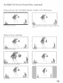
Thank You for Your Purchase
Welcome to the wonder%l and exciting world of digital television! We are honored that you chose Mitsubishi
as your premier home entertainment
partner. The development team at Mitsubishi Digital Electronics America
(MDEA) understands that our customers demand and expect the very best. MDEA was founded on the
core beliefs and philosophies that drive us to deliver products that implement the latest in advanced television
technology_
While some televisions are destined %r obsolescence
upgradeable. This cornerstone
enjoyment for years to come!
in the near %ture, MDEA's
of your home entertainment
televisions
are all HD-
system will continue to provide unparalleled
Whether this is your first Mitsubishi consumer electronics product or another addition to your growing
Mksubishi system, we hope that this television will bring you many hours of enjoyment.
9
Unpacking Your New TV System
Please take a moment to review the following
gJjLcI)r)i.Way
list of items to ensure that you have received everything
(J) Owner{__Guide
(l) Registration
./'orL7:4260
(4)Mou.tingHooks (2)_ gdts
Included
in the HD-6000
carton
(8)M4gdts
are the following
(I) USB Cable
below:
(I).4C
Cord
Card
(d CarteManagement
co_er
(4)TieWraps
items:
T2ZZZZZT_
/
(J) HD=6000 Digital Cable Ready
HDTK Receiver/Contro]]er
(2) AA
Batteries
(1) t-tDMt
(1) HD-6000
Owner _ Guide
Cable
©®®
(I) Registration
(1) RS=232C
Cable
Card
(I) Remote Control
(J) AC Cord
Sp ecla" 1Fe atures
Your new I,T-4260 High Definition Television System has many special features. This makes it the perfect
control center for your home entertainment
system. These special features include:
Mukiple Connection
On the HD-6000
sophisticated
Fh:eWire%
Capabilky
back pane] you wi]] find
home
]EEE
theater
system.
a fu]] comp]ement
Inc]uded
1394, Cab]eCARU
are standard
of the connections
needed
Audio/Video/S-Video,
rM and both an HDM]
rM Input
for the most
wideband
and an HDM]
component
video,
rM Output.
TV Disc Internal Digkal Video Recorder (DVR)
TV
Disc is an internal
DVR).
120GB
It is able to record
Antenna
2, devices
as 12 hours
can record
high
digka]
connected
of high
to Input
definition
a high definition
Recordings
on the TV
TX&. When
recording
definition
and analog
hard
and watch
stereo to high quality
digka]
programs,
stereo
TV
1394 devices.
provider's
Mitsubishi
one-way
HDTV
digital
signals
used in place of a traditional
your local cable provider
NetCommand
Your
Mitsubishi
with
new and future
quahty
VCRs
or to other
1394 to DzVHS
with
Do]by
system
(AV/C),
cable boxes
The HD-6000
11
5C copy protection
or satellite
ma W devices,
products.
allowing
receivers.
offers
and IR control
NetCommand
you to customize
with instant
replay.
as much
Now you
]oss and without
IEEE
a VCR.
1394 cornpatib]e
<_Record
to convert
Digita] <_decoding
surround
receivers.
is "Plug-and-Play"
ready,
'rM security
cable programming
and service
Control
NetCommand
may record
or
1,
the ana]og
TM)
cable box to access digital
information
recorder
Antenna
Digita]
the use of a CableCARD
receiver/controller
digital
feature
any picture
® Home Network
HDTV
exciting
video
rv channels,
live TV pause
receiver/controller
for availability
This
Disc wi]] even use Dolby
compatible
with
(also ca]]ed a digka]
CableCARU
and includes
Digkal CaNe Ready (CableCARD
Your widescreen
from
it later without
Disc can be sent by IEEE
ana]og
received
1, 2 or IEEE
TV programming
program
disk drive recorder
programs
of selected
includes
the NetCommand
module.
The
(including
a cable
CableCARD
sM is
high definition).
Contact
details.
System
a new level of networking
supports
lit can descramble
]EEE
older products
the ability
system
to combine
1394 connections,
to learn
such as VCRs,
remote
control
in a way that works
is designed to work with all of the features of the Mksubishi
selected
Audio
older products
Video
DVD
signals
Control
players,
directly
from
best for your viewing.
I,T-4260 LCD HDTV
display.
Side Control Panel and Card Reader
Many ,:emote conn:ol buttons are duplicated
page 37, for an explanation ofthei,: usage.
on the side conn:ol panel. Please see Remote
Conn:ol Funcnon,,
CONTROL PANEL
CARD READER
(left side of LCD Display)
(right side of LCD Display)
POWER
A
A
VOL
ADJ
V
V
?>
g
O3
oo
A
_
CH
ADJ
T
4
©
>
70
C_
g
Z
©
9o
Co
C_
"7"1
5
FORMAT
ENTER
MENU
MENU
©
>
7o
E_
4:a
g
m
GUIDE
3
o
CANCEL
Q
K;
DEVICE
See Media Card Playback,
Page 64, For Details.
The AI)JUSZ
ENTER,
?WEN{!, and CANCEL
buttons may be used to access or navig_tte throug/J the screen menus
12
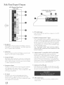
Side Panel Input/Output
LCD Display Side Panel
(right side)
LCD
Dispmay
Back
Panel
(right side)
@
®
®
@
A
6_
PC Audio Input
This is used to send the sound }'tom a computer
Displays speakers.
,
to the LCD
--
Z HDMIrM/MonitorLink
TM
Input
This is a Mitsubishi-exc_t_sive proprietary digkal interface f'or
die display of high quahty digka_ video signals f)'om Mitsubishi
products such as the HD6000
HDTV Receiver/Controller.
AII video signaIs, both analog and digitaI are sent digitaI1y to
your Mitsulmshi TV. Can also be used as a HDMI TM input
fi._rother compatible sources.
Note: The HDMIVM-HDTVinput
terminal is compliant
with the EIA-861 standard and is not intended for use with
1. Hea@hone
The Headphone Output sends the LCD Displays connected
audio signals to a pair of headphones, The audio output f)'om
the TV's speakers will be unavailable.
personal
computers.
2. Audio Out
The Audio Output sends tl_e LCD DispLays com_ected audio
signals to an A/V receiver or other equipment.
3. Composke
8_
Input
Input
This input can be used _>r the connectim_ of A/V equipment
wkh component video outputs, such as a DVD player or
compatible Video Game System. Please see Appendix A, page
6!, fbr signa_ compadbihty.
5_
TM
contro]/RS-232C
for HD-6000
A digital control interfi_ce that works in paralld wkh
MonitorLink TM, While MonitorLink TM provides tlxe digital
vide(> signal, MonitorLink TM Control provides enhanced
f\mctim_ing such as automatic power ON/OFF and input
sdecdon.
Can also be used with other compatible RS-232C
external devices. Please visit wwv<mitstd>ishi-t>com
fi>r more
These inputs can be used for the connection ofa VCR, Super
VHS (S-VHS) VCR, laser disc player, or other A/V device to
the TM Wkh each input, you may connect to tl_e S-VIDEO
or VIDEO terminal but not to both.
4. Component
MonitorLink
infi>rmadon
9_
Authorized
or RS-232C
Card
command
structure.
Reader
This USB input connects _
to the HD 6000 and enables
tl_e use of the media card reader _ocated on the LCD Display
side panel See Page 64 f_>rdetai_s.
PC Input
This input can be used fbr analog RGB signals from a
personal computer. Supported resolutions include VGA,
SVGA, XGA, and WXGA on1> Please see Appendix B, page
6! f'or supported
13
PC Resohidons.
10. DVI Audio Input
(Jse this input to provide sotmd when an HDMI
adapter is used.
to DVI
Attaching
Set-Back
HD-6000
Configuration
Connecting
Stand
Alone
Connecting
wall Mount
Connecting
to 42" LCD
a Computer
Configuration
a Computer
Configuration
a Computer
Display
................................................................
Setup ..................................................................................
............................................................................................
Setup
.............................................................................
..........................................................................................
Setup .............................................................................
............................................................................................
15
16
20
21
22
23
2-
Television
The
),T-4260
a HD-6000
system
System Setup
LCD
Television
Digital
Cabl
has to offer,
attach
e
System
Ready
HDTV
the HD-6000
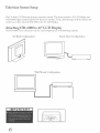
Attaching HD-6000
The
HD-6000
is extremely
can be connected
versatile.
Receiver/Controller.
to the 42" LCD
The
System
a 42" I_CD
To take full advantage
Display
of all the features
Display.
to 42" LCD Display
to the 42" LCD
Display
by one of the following
methods.
Stand Alone Configuration
Set-Back Configuration
\Vall Mount Configuration
15
includes
and
this
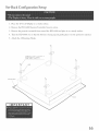
Set-Back Configuration
1. Place the 42" LCD
Display
2. Remove
the HD-6000
3. Remove
the protective
4. J)rn
the HD-6000
5. Attach
Setup
on a sturdy
surfi/ce.
Receiver/Controller
material
from its carton.
from around
over so that the bottom
the 4 Mounting
the HD-6000
is _acing
and place it on a sturdy
up and gently
surface.
place it on the protective
material.
Hooks.
SCREW(M4:2
PIECES
BOTTOM SURFACE OF
x 4 PLACES)
FID6000
TO
SCREW TORQUEiIS_2Okgfcm
Pro_ective Sheet
\
\
\
\
\
/
\
_FID6000
16
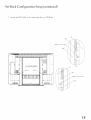
Set-Back Configuration
6. Grasp
mounting
the HD-6000
hooks
connect
Setup (continued)
fl:om the top and bottom.
to the corresponding
Slide the HD-6000
pin located
P_N ON
on the LCD
into place
Display
making
sure that
stand.
LCD Display
\
\
PIN ON LCD Display
\
_HOOK
PIN
PIN
ON
LCD
Disp
ay
ON
LCD
Dspay
ON HD6000
all 4
Set-Back Configuration
Z
Secure
the HD-6000
Setup (continued)
to the stand
using
the two M3 Bolts.
STB
HOOK
\
<
\
SCREWIM3:I PIECE) TO HOOKI
\
\
\
\
\
\
.
/
DETAIL A
STB
J
HIHIIIHI
HIHIIIHI
HIHIIIHI
UUIHIIIUUI_
DETAIL A
DETAIL B
X
01101001000
_
[]
HIHHIH_
HIHHIN
_ HIHHIm
HOOK
,//
J
L_ I_I_;;I;II;IH";II;II;I;IHH;I;I;;II;IIH;I;II;I;IIr_TnlI_
UI_ IIIIHHIH IHIHIH_
Iln IOOIHHI_ IHIHIH_
IHHIHI_
IHHIHI_
IHHIHII
IHHIHIO
SCREW[M3:I PIECE} TO HOOK.
IIU
IH
J
STAND
J
\
j
BETAI L
18
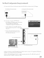
Set-Back Configuration
8, Connect
the HDMP
M Cable
HDMP'MiMuniturLink
HD-6000
input
Back
Panel
Setup (continued)
@ore the HDMP
connector
(section
located
M Output
connector
on the back of the HD-6000
on the back of the LCD
detail)
LCD
Display
to the
Display.
Back
Panel
(section
detail)
!
9. Connect the USB Cable f?om tbe Authorized
the AUTHORIZED
HD-6000
10. Connect
Back
the RS-232C
the HD-6000
LCD
CARD READER
Panel
(section
Cable
connector on the back of the LCD Display,
detail)
LCD Display
@ore the MonitorLink
to the RS-232CiMuniturLink
rM Control
'rM Control
Back
Panel
RS-232C
fur HD-6000
(section
connector
connector
detail)
on the back
on the back
Display:
HD-6000 Back Panel (section detail)
@_®e@@@e eee
e® eee
e®
-/,____S--
19
Card Reader connector on the back of the HD-6000 to
LCD Display Back Panel (section detail)
of the
of
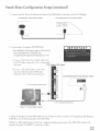
Set-Back Configuration
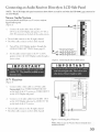
11. Connect
Setup (continued)
the AC Power Cord @ore the back of the HD-6000
HD-6000
Back Panel
12. Connecting
(section
a Computer
° Your Mitsubishi
detai!)
LCD Display
Back
to the back of the LCD Display.
Panel
(OPTIONAL)
(section
detail)
_NPONT&NT
LCD dispIay supports VGA, SVGA,
XGA, arid WXGA PC resolutions on@
.geeAppendix
B: Supported
a. Ccmnect a Mi@ D-sub
PC Resolutiorls, P. 6l
15-p@ (RGB) cable from
the LCD D_splay back panel to PC or Mac@tosh®
back panel.
LCD Display
Side Panel
®
b. Connect
a PC Audio Cable (or 1/8" stereo
mini jack cable) f'rom the LCD
PC or Macintosh
@
@
side panel to
back panel.
@
@
@
@
@
@
@
@
@
to PC or Macintosh@ back panel
LCD Display Back Panel (section detail)
®
@
@
to PC or Macintosh@ back panei
Figure
Z Connecting
Computer
13. Refer to Chapter 2 (in the HD-6000
Owner's Guide) on how to connect A/V equipment
Cable Box, etc) to the back panel of the HD-6000.
14. Refer
features
to HD-6000
that the LCD
Owner's
Guide
for corr@ete
HDTV
system
has to offer.
operating
instructions.
The
HD-6000
(DVD
controls
player,
all
2O
Stand Alone Configuration
Setup
1. Place the 42" LCD Display on a sturdy surfhce.
2. Remove the HD-6000
Receiver/Controller
3. Place the HD-6000
Receiver/Controller
4. Connect
_MCable
the HDMY
the HDMP'MiMonitorLink
from
Back Panel
on a sturdy
the HDMP
'rM_[NPUT
HDo6000
from its carton.
"MOutput
connector
(section
surface.
located
detail)
connector
on the back of the HD-6000
on the back of the LCD
LCD
Display
Back
Panel
to
Display:
(section
detail)
®®
_®,®
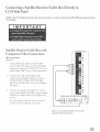
5. Connect
the USB Cable fi:om the Authorized
the AUTHORIZED
CARD
HD-6000
6. Cormect
Back Panel
the RS-232C
of the HD-6000
LCD
.....
2::2::::
Cable
READER
(section
from
Card Reader connector
connector
on the back of the LCD Display.
detail)
LCD Display
the MonimrLink'
to the RS-232CiMonitorLink'
FM
on the back of the HD-6000
Control
Control
Back
RS-232C
for HD-6000
Panel
(section
connector
connector
detail)
on the back
on the back of the
Display:
HD-6000 Back Panel (section detail)
@@÷@@@@ ®@e
@@@@@ @@@
LCD Display Back Panel (section detail)
to
Stand Alone Configuration
7. Connect
the AC Power
HD-6000
8. Connecting
Back
Panel
a Computer
• I/::ur Mi:subishi
XGA,
Cord
arid
LCD
WXGA
See Appendix
@ore the back of the HD-6000
(section
detail)
LCD
to the back of the LCD
Display
Back
Pane! (section
Display.
detai!)
(OPTIONAL)
dispIay
supports
PC resolutions
B: Suppor:ed
a. Comaect a Mi@ D-sub
Setup (continued)
VGA,
SVGA,
only.
PC Resolutions,
P. dl
15-pin (RGB) cable f'rom
the LCD Display back panel to PC or Mac@tesh@
back panel,
LCD Display Side Panel
®
b. Connect
a PC Audio
Cable (or 1/8" stereo
mini jack cable) @ore the LCD
side panel to PC or Macintosh
@
@
Display
back panel.
@
@
@
@
@
@
@
@
@
to PC or Macintosh@ back panel
LCD Display Back Panel (section detail)
®
@
@
to PC or Macintosh@ back panet
Figure Z Connecting
9. Refer
Cable
2 (in the HD-6000
Box, etc) to the back panel
10. Refer
features
to Chapter
Computer
to HD-6000
that the LCD
Owner's
Guide)
on how to connect
A/V
equipment
(DVD
player,
of the HD-6000.
Owner's
Guide
for corr@ete
HDTV
system
has to offer.
operating
instructions.
The
HD-6000
controls
all
22
_agall Mount
Configuration
1. Be%re
per%truing
work make
2. Before
performing
work spread
the protective
will prevent
the display
even surface°
3. Gently
This
lay the LCD
4. Do not touch
5. Remove
Display
sure to disconnect
face down
or hold the screen
the screws
indicated
Setup
the AC Power
sheet,
which
from being
carrying
by the arrows.
Remove
was wrapped
around
Display:
the display,
on a flat,
damaged.
on the protective
face while
cord fl:om the 42" LCD
sheet.
the display.
the stand
cover.
Protective Sheet
\
____I
glgllllllllllllllllgllllll
________________________________________________________________________________________________________________
__________________________I____I_I____________________________________________I______I_I________________________
STANDCOVER
STANDCOVER
-.<
o o o
IHIIHIIII
IIIIIIIIIII
IIIIIIIIIII
IIIIIIIIIII
IIIIIIIIIII
IIIIIIIIIII
HII
HH
23
=
IHmHH
HHHHH
HHHHH
HHHHH
HHHHH
HHHHH
HHHHNN Ill
HHHHII HI
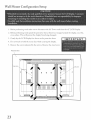
Wall Mount Configuration
Setup (continued)
6. Remove the Sc,:ews Mdicated by the ai:i:ows.
Protective
Sheet
!'"'
\\_
R_H_RH_iHHHHH_IHHHIHHHHHHHHHHHHHHHHHHHHHHHIHHHIHHUHHHHHHHHHH_
=
=
iiiiiiiiiin
_InHHHHHH_
IH_ lllmHH
HH HHHHH
o.
HHHHH
HHHHH
HmHH_
HmHH_
HmHlll
HmHH_
HH
HH
.o
24
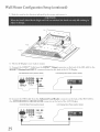
Wall Mount Configuration
2
Slide the stand ir_ the direction
Setup (continued)
indicated
by the arrows and remove it.
LCDDisplay
\
\
\
Protect_Sh_et
\
\
8. The LCD
\
Display is now ready to mount.
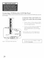
9. Connect the HDMI
HDMI'rMiMonitorLink
HD-6000
10. Connect
*'MCable @ore the HDMU M Output connector on the back of'the HD-6000
INPUT connector located on the back of the LCD Display:
Back
Panel
(section
detail)
LCD Display
the USB Cable from the Authorized
the AUTHORIZED
HD-60O0
CARD
Back
Panel
READER
(section
detail)
Card Reader
connector
connector
Panel
(section
detail)
on the back of the HD-6000
on the back of the LCD Display.
LCD Display
/
25
Back
Back Panel
(section
to the
detail)
to
Wall Mount Configuration
Setup (continued)
11. Connect the RS-232C Cable @ore the MonitorLink
Control
HD-6000
to the RS-232CiMonitorLink
Control for HD-6000
RS-232C connector on the back of the
connector on the back of the LCD
Display.
HD-6000
Back
Panel
(section
deta/)
LCD Display
Back Pane!
(section
detail)
@@ ®@@ @@ @@@
@@@@@
L
12.Connect
Y--
the AC Power Cord @ore the back of the HD-6000
HD-6000 Back Panel (section dotal)
to the back of the LCD Display.
LCD Display Back Pane! (section detai!)
r
26
agall Mount
Configuration
13. Connecting
a Computer
° YourMitsubishi
Setup (continued)
(OPTIONAL)
LC@ display sugports VGA, SVGA,
XGA, arid WXGA PC resolutions onl@
See Appendix
B: Stcpported PC Resolutions,
a. Comlect a Mi@ D-sub
P. dt
15-pha (RGB) cable _'rom
the LCD Display Back panel m PC or Macintosh@
back panel.
h. Connect
a PC Audio Cable (or 1/8" stereo
mini jack cable) f'rom the LCD
PC or Macintosh
side panel to
back paneh
LCD Display Side Panel
®
@
@
@
@
@
@
@
@
@
@
@
to PC or Macintosh@ back panet
LCD Display Back Panel (section detail)
m
®
@
@
to PC or Macintosh@ back panel
FTgure 7. Connecting
Computer
14. Refer to Chapter 2 (in the HD-6000
Owner's Guide) on how to connect A/V equipment
Cable Box, etc) to the back panel of the HD-6000.
15. Refer
features
27
to HD-6000
that the LCD
Owner's
Guide
for complete
HDTV
system
has to offer.
operatir_g
instructions.
The
HD-6000
(DVD
controls
player,
all
Connections
Connecting
a VCR directly to LCD Side Panel .............................................................
29
Connecting
an Audio Receiver ......................................................................................
30
Connecting
a DVD Player or Other S-Video Device .....................................................
31
Connecting
a Satellite Receiver/Cabie
32
Box ....................................................................
Con necting MonitorLink TM or a Computer ................................................................
How Connections Affect the PIP and POP .......................................................................
33
34
Connecting
a VCR directly to LCD Side Panel
theLCDDispl_
Composite Video with Audio or S-
LCD Display Side Panel
Video with Audio (Recommended)
®
@
(Figure 1)
i.
®
@
@
@
@
@
@
2_
®
back
panel
FTgure 1. Cormect@g
29
Com_ect a set of"audio cables fi:om AUDIO OUT
o1_the VCR back panel to VIDEO INPUT/
AUDIO RIGHT & LEFT o1_the LCD Display
side pal_ek
@
@
VCR
Connect a video o1:a S-Video cane fl:om VIDEO
OUT on the VCR back pand to VIDEO INPUT
on the LCD Display side pal_ek
Attach
only
channelorRFON/OFF
cable
switch, set to OFF.
type
the UCR Audio/_deo.
° The red cane com_ects to the R (righ0 channd
° The white cane com_ects to the L (]eft) channel
You may connect to the S-VIDEO
terminal but not to both.
or VIDEO
Connecting
an Audio Receiver Directly to LCD Side Panel
NOTE:
The LCD Display
the LCD Display.
side panel connections
shown below can only be used when the HD,6000
is not Connected to
Stereo Audio System
(recommended
for shelf units or AiV receivers without
LCD Display
digital audio inputs)
(Figure 2)
1.
Cormecr
OUT
the audio
o1_ the LCD
AUX ]N terminals
Turn off the LCD
AUDIO/VIDEO
3.
Panel
®
R÷d
canes
@
fi:om AUDIO
Dispby
side pand
White
@
@
@
@
@
@
@
@
@
ro TV IN o1:
on the back of the audio
system.
° The red cane connects to the R (rigb0 cbannd
° The white cabJe com_ects to the L (left) channel
2.
Side
Display
speakers
SETTINGS
through
Menu,
the
page 52.
®
@
@
Set the audio system's iHput to the TV ol1AUX
position to bear the LCD Displays audio through a
stereo system°
Figure 2. Connecting the Stereo Audio System.
A/V Receiver
(Figure
,
3)
Cormect either a video cable ol1a S-Video cable
(but not both) from VIDEO MONITOR OUT
o1_the back of the A/V recdver to VIDEO INPUT
LCD Display Side Panel
on the LCD Display side panek
_d
2.
Com_ect
a set of audio
cables from AUDIO
o1_ the LCD Display side pal_ei to AUDIO
on the back of the A/V receiver.
OUT
TV 1N
° The red cable connects to the R (rigb0 cbam_el
* The white cable com_ects to the L (left) channel
FTgure 3. Connecting the A/VReceivero
detailed connections.
3O
Connecting a DVD Player or Other S-Video Device Directly to
LCD Side Panel
the LCD Display.
DVD Player/Video Game with
®®
n
Video
(Figure 4)
@
@
@
@
@
@
@
@
@
f
f
Component
.
LDD Display
Side Panel
®
@
@
DVD back
panel
2.
.............................................................................................................................................
Connect the Component Video cables from
(YCb Cr o!: YPb Pr) VIDEO OUT on the back
of"the DVD pbyer to COMPONENT
VIDEO
INPUT on the LCD Display side panel The correct
connections are:
A. YtoY
B. Cb o1 Pb to Pb
C. Cr o1 Pr to Pr
J
Figure 4. Connecting a DVD Player voidaComponent Kideo.
Connect a set of audio cables from AUDIO OUT
on the back of"the DVD pJayer ro COMPONENT
V_DEO Input/AUDIO RIGHT & AUDIO LEFT
on the LCD Dispby side panel
° The red cable connects ro the R (rigb0cbannd
° The white cable connects ro the L (Jeft) cbannd
NOTE:
Some video game systems
support
corr_ponent
connections.
Please refer to your video game
consoJe Owner's Guide.
NOTE:
LCD
Display
Side
Kyour
DVD
scan pJayback,
Pane_
pbyer
supports
progressive
be sure to set your player
accordingly.
Please refer to your DVD
Owner's Guide.
@
@
@
@
@
@
@
@
@
@
Other S'Video
(Figure
1.
Device
5)
Connect a S-Video cane fl:om VIDEO OUT on the
device back panel to VIDEO INPUT
Display side panel
@
player_
on the LCD
®
2.
@
@
,
S-Video Device
Connect a set of audio cables from AUDIO OUT
on the device back panel to VIDEO I/NPUTi
AUDIO KfGHT & AUDIO LEFT on the LCD
Dispby side panel
° The red cable connects to the R (right) cbannd
° The white cable connects to the L (Jeff) cbannd
Figure
5. Connecting
31
an S_deo
Device.
Connecting a Satellite Receiver/Cable
LCD Side Panel
NOTE: The LCD Display side pm_e! Connections
LCD Display.
Satellite Receiver/Cable
Component
Box Directly to
Shown bdow Can only be used when the HD:6000
Box with
Video Connections
is not Connected to fl_e
LCD DispJay
Side Panel
®
(Recommended)
(Figure
1.
6)
Connect
RCA-type
receiver/CabJe
side panel
cabJes fi:om the Satellite
Box outputs
Component
used f'or 480i, 480p,
to the LCD
VIDEO
720p
Display
INPUT
may be
or 1080i components.
Connect the L deft) and R (right) audio
cables f'rom the Satellite/Cable
Box receiver to
2_
COMPONENT
RIGHT
VIDEO
& AUDIO
LEFT
INPUT/AUDIO
on the LCD
Dispk_y
side panel.
.
To utilize
connect
the benefits
of a digital AIV receiver,
your Satellite/Cable
audio out to a digital input
receiver.
Box: receiver_
digital
on your digital A/V
See your Satellite/Cable
Box receiver and A/V
receiver Owner's Guides f'or instructions.
f'igdre 6. Connecting a Sate]]ite receiver °with
component Kideo Connections.
32
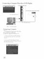
Connecting
a Computer
Directly to LCD Display
LCD Display Side Panel
®
@
@
to PC or Macintosh@ back panel
@
@
@
@
@
@
@
@
@
LCD Display Back Panel (section detail)
/-
®
@
@
to PC or Macintosh@ back panel
FTgure 7. Connecting
Connecting
Computer
a Computer
(Figure 7,,I
" YourMitsubS"hi
XGA, and WXGA
See Appendix
a. Comlect
LC@ display supports VGA, SVGA,
PC' resolutions only.
@: Supported
PC Resolutions,
P. dt
a M@i D-sub 15-p@ (RGB) cable from
the LCD Display Back pane! to PC or Macintosh@
back panel.
b. Connect
a PC Audio Cable (or 1/8" stereo
mini jack cable) @ore the LCD Display
PC or Macintosh
33
back panel.
side panel to
JR
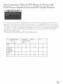
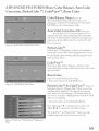
How Connections Affect the PIP (Picture-In-Picture)
and
POP (Picture-Outside-Picture)
and DW (Double Window)
7_> see a picture
equipment
LCD
Display,
used together.
they may have.
1080i),
in the PIP, POP
is connected,
format,
See Operation
it is important
The
or Double
Window
you may need
you may be able to view these
to understand
table on this page
If you press the INFO
which
shows which
button
input
main
sources
picture
inputs
to select
as the
an input
PIP/POR
and PIIP/POP
can and cannot
it will display the current
input
source.
sources
be used together
Input
signal
If other video
When connecting
(480i,
your
can and cannot
be
and the limitations
480p,
720p,
or
and sleep time.
of PIP
Component
480i, 480p,
720p, 1080i
HDMI
and POP,
page
60, for operating
instructions.
(-)K
(-)K
(-)K
(-)K
OK
OK
OK
OK
(-)K
(-)K
(-)K
(-)K
(-)K
(-)K
(-)K
(-)K
34
This page
35
lea
Overview
of the TV Laver Buttons ...............................................................................
37
Operation
......................................................................................................................
38
Sleep Timer .....................................................................................................
Use With Other A/V Products ......................................................................................
39
40
Operation
42
of P1P. POP and Double Window
...............................................................
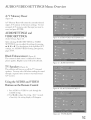
Remote Control Functions:
Overview of the TV Layer Buttons
Overview
18+FORMAT:
(Figure
8, fbllowing
1+Slide
Switch:
by the remote
and other
iInput,
Select
7)rns
A/V
power
connected
3+DEVICE:
A/V
Select
5+MUTE:
product
to be controlled
LCD
Display
Manually
20+REW/REV:
reverse
record with a VCR or recordable
Rewind o1: reverse search with a
scan with
a
DVD, o1:skip reverse with a
CD.
to view;
Component,
21+PLAY: Play a VCR, DVD, or CD+
sound
sound
19+REC:
DVD+
VCR,
products.
TM.
Change
Turn
on and offfor
the input
PC, o17HDMI
4+VOLUME:
the shape and size of the
page)
control.
2+POWER:
Change
22+STOP:
level+
23+FF/FWD:
on or off+
6-TV MENU: Displa y _INP01nl®on+screen menu
Stop a VCR, DVD, or CD+
Fast forward or forward search with
a VCR, fast play with a DVD, or skip
forward with a CD.
system.
7+ADJUST:
Navigate
menus, change
move the PIP on+screen location.
settings,
and
8+ENTER:
or menu
item.
Select
a channel
9+HOME:
Exit on-screen
10+INFO:
Display
input
menus
on+screen
used and arty broadcast
(including
current
Additionally,
number
Signal
and return
summary
information
Source
to TV
of the current
available
and Format)+
if you press the INFO
key, it will display
sleep time.
11+AUDIO:
Select
the individual
audio
settings.
12+VIDEO:
Select
the individual
video
settings.
13+PIP CH: Scroll up or down
channels
in PIP or POR
14+PIP!POP:
choices.
15+EXCH:
picture+
through
memorized
Cycle through PIP and POP display
Exchange
PIP o1:POP with the main TV
16+SLEEP: Set the LCD Display to turn off
within 2 hours. See Sleep Timer, page 39, for setup
instructions.
17+PIP DEVICE:
source.
37
Select the PiP or POP input
24+PAUSE: Pause a VCR, DVD, AV Disc, o1:fi:eeze
the PIP or POP image+
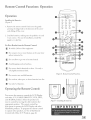
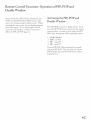
Remote Control Functions: Operation
_i
Operation
F_
@RM-6000
G
Installing the Batteries:
(Figure 9)
1. Remove
the remote
comrol's
pressing
the ridged
tab in the directiol_
and sliding
back cover by gendy
of the arrow
off the cover.
2. Load the batteries,
(-) are correct.
negative
-@
making
sure the polarities
For ease of installation,
(+) a,_d
i,_staH the
(-) side first.
For Best Resuks
Be within
from
the Remote
Control:
20 f_et of the equipment.
_.
Do not press two ol1 more
unless instructed
to.
_.
Do not allow to get wet ol1 become
_.
Avoid dropping
at the same time
buttons
heated.
on bard surfaces.
Do not use harsh cherrficaJs
soft, ]ighdy moistened
to dean.
Use onJy a
cloth.
Do not mix new and old batteries.
_.
Do l_ot heat, take apart,
_.
Use only AA batteries.
ol1 throw
batteries
il_to fire.
batteries
,_o_m _
Operating
the Remote Control:
You can use the remote to control
and other A/V (CABLE/DBS/DTV,
and
want
AUDIO)
products.
to control
appropriate
been
position.
preset
Mitsubisbi
to operate
Control
to operate
products.
other
with
Select
by moving
The
the product
remote
the LCD
A/V
control
Display
Oi
you
the slide switch
7b program
products,
Other
the LCD Display
VCR, DVD,
size AA
to the
has
and other
the remote
control
see Use of the Remote
Products, page 40.
38
o
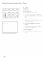
Remote Control Functions: Sleep Timer
Sleep Timer
(Figures 10 & 11)
Setting the Sleep Timer:
J.
Pl:ess SLEEP oll the 1:emote coNtl:ol.
2.
iNdicatillg the lellgth of time the sJeep
timeu: is to be set appears oll the scl:eell of'the LCD
Display.
3.
Each wess of'SLEEP
FTgure 10. Sleep button on remote control
will iNcl:ease the time
displayed by 30 mim_tes, tmtil the maximum
of" 120 mim_tes is l:eached.
Sleep:
4.
30 rain.
Af'reu:5 seconds ofillactivity,
&_appeal:.
Pl:ess SLEEP
dine1: turns
Canceling
j.
39
sleep timer
Display
time befi_l:e the
of}:
the Sleep Timer:
Pl:ess the SLEEP burro11 to display the oN--scl:eell
message.
FTgure ii. On-screen display,_r
the message will
to view the remaiNillg
the LCD
vak_e
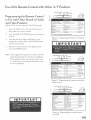
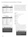
Use of the Remote Control with Other A/V Products
CABLE/DBS/DTV
TV-_
Programming
the Remote
(
Control
to Use with Other Brands of Audio
3.
Cable box brand
and Video Products:
(Figures
1.
12-14 this page, figures
Move the slide switch
the product
2.
_ VCR . DVD
I
_ _ _-AUDIO
15-16 f_llowing
at the top of'the
Genera!
Jerrold
page)
remote
to
Press and hold the POWER
buttol_ o1_ the remote
119,120,121,122,123,
124
125,126,127
Oak
Pioneer
139,137,102
101_I16
112,113
117,100
Atlanta
If your
cable box
code is not
listed here,
please see
page 62
fora
Motorola
Scientific
Zenith
you want to controk
C0det0enter:
Instruments/
complete
listing.
To reset to default code, enter 000
controk
3_
equipment,
and then rdease
on the remote colin:o[.
4.
Point the remote
press the POWER
Note:
PYgure 12. Programming
cable box.
Enter the first three digit code listed f'or yore:
If'the
control
to the equipment
responds,
programmed
]f the equipment
buttol_
and
button.
equipment
properly
the POWER
the remote to control your
the remote
to operate
does not respond,
control
is
CABLE/DBS/DTV
TV_
the equipment.
repeat
_ VCR _ DVD
_ _ It _AUDIO
steps
2-4 with the next three digit code listed in step 3
f'or your equipment.
3
Satellite
brand
Code to enter:
Mitsubishi
DTV - DBS
DishNetwork
006
175
173
Hughes - DBS
Panasonic - DBS
RCA - DBS
174
176
177
Sony -DBS
Toshiba-DBS
170,173r 189r 190r 19'I
If your
satellite
receiver
code is not
listed here,
please see
page 63 for
a complete
listing.
To reset to default code, enter 000
Figure 13. Programming
satellite receiver.
CABLE/DBS/DTV
TV_
the remote to control your
_ VCR . DVD
_
_
_
_AUDIO
1. C
_\
2
,
VCR brand
Codetoenter:
Mitsubishi
Hitachi
JVC
00!,002
020,043,065
Philips / Magnaw)x
Panasonic
RCA
043,044,05!
Sony
Toshiba
030,054
04!,042_043
020,053,065
048,049,050
02!
If your
VCR
code is not
listed here,
please see
page 63
for a
; complete
listing.
To reset to default code, enter 000
PTgure 14. Programming
your VCR.
the remote to control
Use of the Remote
CABLE/DBS/DTV
c
Control
with Other
_ VCR _DVD
TV-_
_, _
_
A/V
After
_.AUDIO
4:44k
entering
remote
Code to enter:
003
257
If your
DVD
code is not
listed here,
please see
page 62
for a
250
258,253,272
252
261
complete
listing.
254
If you enter
mute functions
TV
is usefu]
all the time.
below
devices
code, enter
F)gure 15. Programming
D VD or LDP.
is set to
is allowed
of the
which
button
the AUDIO
is
chart
TV, the volume and
to match
using
an A/V
In all other
the A/V
receiver.
receiver with the
cases, only one of the
for each slide switch
position.
000
the remote to eontrol your
TV position:
e_ TV
e_ A/V receiver
CABLE/DBS/DTV_ VCR .DVD
TV-,_ t {, $ ,-AUDIO
l
an operational
a code from
change
when
to sdect
253
To reset to default
1. c.:
when
while the slide switch
This
codes in each position
use the slide switch
will respond
pressed.
DVD/LDP brand
Mitsubishi
JVC
Panasonic
Philips
Pioneer DVD
Samsung
Sony
Toshiba
the correct
contro],
product
3.
Products
J[![
/'---.
2.
(vo[ume
and mute only)
Cable/DBS/DTV
position:
Cable box
Satellite receiver
DTV receiver
.
Audio brand
Mitsubishi A/V receiver
and/or CD player
Code to enter:
010,015,011,012,
013,014
Denon
234,235,236,245,
246,359
Harman Kardon
JVC
215,223,242
233,232
208,200
Kenwood
Marantz
Onkyo
Pioneer
Sony
Technics
Yamaha
To reset to default
224350
209,214,240,247
If your
audio
code is not
listed here,
please see
page 62
for a
complete
listing.
205,207
222,249
218,219,221
?N?, 2N1,741,944
code, enter 000
FTgure 16. ProgrammS"_gtl:w remote to eontrol your
H/Vreeeiver.
VCR position:
ga vcR
DVD position:
e_ DVD
e_ LD Player
Audio position:
e_ A/V recdver
Mitsubishi
CD player
]i'yo_ ba_e a Mits_b_sld A/YreceDe_; the a_dio 2ositim_
mW be _sed iv cm!j_nction with select Mit_b£'hi CD
p&yer;. Youra_dio !)ositim_ m_st bepr_rammed
to
either 070 or OH. P!_£ ttae CDp&yerpower cord into a
smitc/sd o_tiet on rise bach o/'yo_u'A/Y receDen Pressi_*g
the POWER b_tton t_rns On tiaeA/YreeeDer, aioJ_£
with ttae CD p&yer. .& the a_d'io i)osidon, )fbr some
C[)p&jers, t/ae transport controls (Fb. P&y, Rew, etc.)
oyeraw the CD y/ayen
Remote Control Functions: Operation of PIP, POP and
Double Window
Picture/In-Picture
(PIP),
(POP)
Window
_md Double
Picture-Outside-Picture
([)W)
features
you to view Programming
in different
watching
you can displ_y
from
the main
other
inputs.
screen,
_f_ see which
cannot
be used together,
Affect
the PIP and POP,
inputs
see How
page
34.
_llow
ways.
Activating the PIP, POP and
Double Window
While
programs
can and
Connections
Press
PIIP/POP
to choose
a display
format.
Each
time the PIP/POP
button is pressed on the remote
control (within 3 seconds of each other), the PIP/
POP
cycles through
1. Double
the following
display
options.
Window
2. POP:
one POP
3. PiP:
4. Pl[P:
large PiP
small PIP
71_ turn PIP/POP
Off, wait at least 10 seconds,
and press PIP/POR
The next time you activate
PIP/POP, the last used PIP/POP
format will be
displayed f_rst.
42
This
page
intentionally
5
_le ViewPoint®
AUDIO/VIDEO
Menu System ......
SETT INGS Menu .........
The
Your
Menu System
TV has Mitsubishi
infi_rmation
for menu
A picture
choices
_
®
J_J_P_J_l on-screen
A[)JUST
using
arrows.
menu
the remote
When
will appear
system,
which
provides
on-screen
and
control's
selected,
the
or start an automatic
function,
You may then make changes
menu or access available sub-menus,
within
the
A highlighted yellow button indicates that you
may make changes to the menu screen.
TheRJNRJff
system_ncludes
the_ollo<ng
special
operating
and changes.
(icon) will be highlighted
can be selected
appropiate
s exclusive
Figure 1Z MAINMenu:
Thejrirst screen that
appears when youpress the TV?CIENUbutton
from
your remote.
features:
The currendy
highlighted
sdected
icon or button
with a rectanguJar
is
yeNow oudine
and
the text coJor win be yeNow.
On-screen
instructions
Some on--screen
other options
The
move
following
quickly
menu
provide
options
complete
menu
must be set before
are avaiJable.
remote
through
control
the
buttons
will help you
_vmNNN
_system
(Figure
18):
AE)! UST A or V to select the menu item you want to
change.
TV MENU
_._
_
r_%_
HOME
AD! UST _ to move to the setting field.
DEVICE
MENU
O
C)
AD! UST A or V to change the settings.
O
O
CANCEL
AD! UST @to move back to the menu item.
ENTER
(ENT)
to enter into a menu, start an
automatic
function,
CANCEL
to dear
TV MENU
HOME
45
or select a checkbox.
a setting,
or stop an automatic
to move back one menu screen
to exit all menus
at once and return
at a time.
to TV
Figure l& These buttons on your remote
control are usedjbr navigation within the
¢_1'
on-screen operatingsystem.
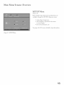
Main Menu Screens: Overview
SETUP Menu
(Figure
19)
Basic (initial)
available
setup
through
instructions
the SETUP
and _hnctions
submenu
are
screens.
* Assign ilnput Assignments
° Sdect
EngJish
or Spanish
or screen dispJay
Set the Front Button
See pages 48-49
F'igure lg. SETUP
Menu
fi_r the menus
Lock
for more detailed
setup
infbrmatiorn
M"am M enu S creens: O vervlew,
"
"
d
continue
AUDIO/VIDEO
SETTINGS
Menu
(Figure 20)
Adjust some or all of the A/V settings. Each input
can be set to your preferences.
A/V Reset on the
menu allows you to return
current
input
the A/V
to the fZactory presets.
settings for the
See pages 52-54
for more detailed setup infbrmation.
Figure 20. AUDIO/VIDEO
ADVANCED
FEATURES
Settings Menu
Menu
(Figure 21)
* Adiust colors atttomatically
Color Balance
or manually,
using
o Display a blue screen when viewing an input
with no signal
o Reduce Power consumption of the display when
connected to a non-active computer
See pages
50-51
for more
detailed
setup
l_Ygure 21. ADVANCED
F_ATURES
34enu
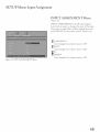
SETUP Menu: Input Assignment
INPUT ASSIGNMENT
Menu
(Figure 22)
IINPUT
turns
ASSIGNMENT
them
iIf you turn
on again
an input
press D-EVIICE
turns
or changes
off unused
the name
Off, it will be skipped
on the remote
control.
inputs,
of the input.
when you
Choices
Cycle through
a list of preset names
Cycle through
a list of preset l_ames or Off
Cycle through
a list of preset names
are:
o1: Off
o1: Off
F_gure 22. INPUTASSIGNMENT?Clenu
48
SETUP Menu: Language, Front Button Lock
Language
(Figure
23)
Display
the on-screen
Spanish
(Espa_iol).
menus
in either
If you choose
selection,
a]] menu
language
of your choice.
Front
Button
English
to change
text will immediately
or
the
switch
to the
Figure 23. Language /idioma
Lock
(Figure 24)
Disable
controls
on the front
from accidental]y
Select
and select Offto
front panel
restore
buttons
of the fiTont panel
the operations
have been
misplace
the remote
control,
function
of the front
panel
the MENU
more than
anyone
of the
buttons.
If the fi:ont panel
holding
panel to prevent
setti ngs.
On to lock out the operations
button
Figure 24. Front Button Lock
changing
8 seconds.
button
locked
and you
you can restore
buttons
the
by pressing
on the side pand
If the LCD
on, a message will be displayed
of the Front Button Lock.
Display
to confirm
and
for
is ab:eady
the release
ADVANCED
FEATURES
Menu: Color Balance, Auto Color
Correction, PerfectColor vM,ColorViewWM, Reset Color
Color Balance Menu (_'_,_u_
25)
The
Color
Balance
(Automatic),
Menu
Color
(ENTER)
V*
Jew
off'ers three
TM
to select Color
Balance
opti mize ski n tone
Color
Figure 25.ADVANCED
F_ATURES
ENT
On (F_gu_
26)
Correction
option
color autom atically
ColorView TM,PerfectColor
grayed out and unavailable
Color Correction.
On
v. Press
Mode.
Auto Color Correction:
Set the Auto
choices:
, PerfectColoP
m On to
and conti nuously.
TMand Reset Color options are
when On is selected for Auto
MENU
PerfectColoK
Perf'ectColor
system.
M
TMis Mitsubishi's
Red,
Green,
be individually
adjusted
other
colors.
spectrum
ColorView
Red, Green,
spectrum
without
color adjustment
affecting
and Cyan
intensity
can
of the
TM
Blue, Yellow,
individually
exclusive
Blue, Yellow, Magenta
ad.]usted
Magenta,
without
and Cyan
af'fbcting
can be
the hues of the other
colors.
Reset Color
Select
to reset the Perf_ctColor
" Each
FTgure 26. COLOR
BALANCE
Menu
active input
can be individually
PerfectColoK
Individual
sliders
where
reset.
M& ColorView
fbr Magenta,
and Blue will be displayed.
value,
settings.
Red, Yellow,
The
63 is the maximum.
each color is 31 (center).
sliders have
The
Highlighted
TM
(Fi_u_27)
Green,
Cyan
a numeric
deftault setting
for
text will show which
slider you are ac_usting.
" Each
Press
Adjust
active input
Adjust
can be individually
,A or v
*_ or _ to change
to navigate
ac_usted.
between
colors and
the color slider settings.
The Color
_
V*1ewTMand Perf_ctColor
TMoptions are only
available when Auto Color Correction
is not On.
Figure
2Z
Co]orYiev_, _M_dYPer]{,etCo]orTJ*_Adjustment
Menu
5O
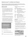
ADVANCED FEATURES Menu: PC Power Save, Video Mute
PC Power Save
(Figure 28)
Your Mirsubishi LCD DispJay fi_Nowsthe VESA
approved DPMS Power Managen-lenr guidelines.
This power
function
rnanagen-lel_t
that auton-laticaNy
consumption
mouse
feature
is an energy saving
reduces
the power
of the display when your keyboard
is inactive
f'or a fixed period
or
of tin-le. Your
dispJay will go into "standby"
and the screen will go
to black. The timer Jight will dispJay amber while in
Figure 28. PC Po_er Save
"standby".
mouse
_[b activate
PC input again,
sin-@y move the
or press a key on the keyboard.
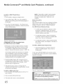
Video Mute
(Figure
29)
Video
Mute,
background
FTgure 29. Video Mute
51
when
when
on, lets you display
no signal
is being
a blue
received.
AUDIO/VIDEO
A/V Memory
(Figure
A/V
Menu: Overview
Reset
43)
Memory
input's
A/V
an input's
reset,
SETTINGS
Reset
will return
memory
A/V
the currently
to the factory
memory,
selected
settings.
select the input
To reset
you want to
and press ENTER.
AUDIO SETTINGS and
Figure 43. AUDIO!VIDEO
(Audio Settings, Figure 44)
SET77NGS
menu
After selecting AUDIO SETTINGS
or VIDEO
SETTINGS,
you can ac_ust the settings by pressing
A, v, 4, or _. For descriptions of the individual A/V
settings, see AUDIO/VIDEO
Setting Descriptions,
pages 53-54.
Black Enhancement (Figure
45)
The
contrast
picture
in dark
quality.
scenes is enhanced
Brighter
for better
scenes will not be affected.
Figure 44. AUDIO
SETYTNGS
_Tgure 45. BLACK
ENHANCEOcIENT
TV Speakers/Figure46)
This
selection
speakers.
will turn
on or off'the
You may select Off when
through
a separate
A/V receiver.
stereo
system
TV's
interna]
sending
the sound
or surround
sound
Using the AUDIO and VIDEO
Buttons on the Remote Control
1. Press AUDIO
or VIDEO
ro cycle through
2. Press @ o1:_ to adiust the settil_g.
of inactivity,
the
After 5 secol_ds
the settil_g display will disappear.
t_Tgure 46. TV SPEAKER
S
52
Q
AUDIO/VIDEO
Setting Descriptions:
Audio Settings
Bass
Enhances
or ,;educes low fi:equency
sound.
Treble
Enhances
ga Balance
or ,;educes high fi:equency sound.
Adjusts the leve] of sound between the left and
right speakers.
ga Surround
Creates
si m u]ated stereo an d surroun d e¢}ccts.
Your choices
are:
" Off: No surround effects. Use this setting
when using an A/V receiver with Dolby sM
Pro Logic Surround, or DoIby sM Digital
Surround.
- Simulated
Stereo: Your TV will create a
simulated stereo effect when watching
stereo program.
" Surround
Sound:
a nona
Your TV will create
simulated surround
stereo program.
effect when watching
a
_1 Level Sound
Automatically
equalizes
the volume
of program
s contai ni ng significant
differences
from
(for example,
one segment
regular
commercials).
music programs,
Off.
level
to anotber
programming
_f_ receive
level
to
the best fide]ity
you can turn
this setting
with
to
Sub Woofer
Y'our TV
is equipped
and a subwoofer.
adjusts
This
the subwoofer's
with two stereo
function
output
speakers
specifically
(level of sound).
NOTE: A slide,; will display on-screen for each
setting. The slide,; has a numeric value, where 63 is
the maximum, the mid-range is 31 and the minimum
setting is O.
53
6
Audio
o
AUDIO/VIDEO
6
Video
Setting Descriptions:
Video Settings
NOTE: A slider wi_ display on-screen f'or each setting.
The slider has a numeric value, where 63 is the maximum,
mid-range is 3! and tl_e minimum setting is 0_
[]
Video media uses a video camera created at 30 f'rames
per second. Film media uses a f'ilm camera created
at 24 f'rames per second. Examples of video media
When tl_e LCD Display is used together with die HD 6000, die
A/V Settings described belnw will be cnntrolled by the HD 6000
except where nnted.
are live TV broadcast
Provides a slide,: to adjust the white-to-black
level. Low contrast shows a variety of shades
in darker images, while high contrast shows
darker images more uniformly black and
makes colors appear more vibrant.
Brightness
the system will never correct fbr conversion
This function
[]
e'! Sharpness 1
Color _
Provides a slider to adjust the proportion
to green.
Display illumination.
A _owcr setting preserves the _ifc of the backhght
_amps.
meLow(w ,rm)
andHigh(cool)
settings.
° High: White images will have a cool cast to
them. This setting may provide the most
realistic picture under bright lighting.
Noise
broadcast
or input
function
(graininess)
in the
signal.
operates
H-Posidnn,
Ck)ck and
takes abnut 5 secnnds.
[] H Position 2
is
° Medium: White images will be balanced between
noise
The whn[e prncess
down (available fi)r PC input only).
[] V_deo Clock 2
° Low: White images will have a warm cast to
them. This adjustment is an average and can
vary due to ambient room lighting, video scene
brightness and the TV's age.
minor
adiust V- Pnskinn,
(7lock-phase.
Provides a slider tn center image by moving it tn
the left nr _
(available fbr PC input only),
[] V Poskion 2
comaected to the LCD Displa>
Allows you to adiust how white images are
displayed. Your choices are:
Reduces
Autnmadcally
Provides a dider to center image by moving it
This Setting is not available when the HD-6000
This
a dider tn adjust the LCD
of red
Color Temp (CoJor %mperature)
Video
only in 480i mode.
[] Auto Position 2
Provides a slider to adjust the color intensity:
[] Tint _
[]
operates
errors.
Back Light
Provides
Provides a slider to adjust the detail and clarity.
or
The settings are On and Off. If you select On, the
system automatically
detects if the signal source is Film
and corrects fbr conversion errors. If you select Of't;
Provides a slide,: to adjust the overall
brightness of the picture.
[]
such as news, special events,
video taped programs.
Examples of f'ilm media are
motion pictures, made-for2F'V movies, and many
prime time programs.
Fihned media is converted by
the broadcaster
or home video company to 30 frames
per second to match TV or vide<> standards.
This
conversion can leave subtle "picture artifi_cts" or
conversion errors.
h_ Contrast
[]
Film Mode (Auto)
tl_e
Provides a slider tn adjust PC dock f)'equenc>
[] Fine DetaiF
Provides a dider tn adjust PC image }'licker (dock
phase).
[] H Resolution 2
Provides a dider tn adjust PC horiznntal size by
increasing nr decreasing the setdng_
[] V Resolution 2
Provides a dider tn adjust PC vertical size by increasing
or decreasing the setdng_
NOTE:
For optimal picture perfbrmance, it is
recommended
that you ad}ust your video settings
(specii_cally contrast and brightness) during initial
setup. Certain fi_ctors will affect your personal
preferences, including room lighting, glare reflections
and viewing
angles/distance.
only in 480i mode.
This setring is nnt available when the HD-6000
(SET TO
PC INPUT) is connected tn the LCD Display. This setting is
available f_)r a_ uther Inputs.
-' Available fbr PC Input only
54
This page intentionally
55
Available
On-Screen
Format
Sizes ....................................................................................
57
...............................................................................................
60
Operation
of PIP and POP
Appendix
A: HD input
Connection
Appendix
B: Supported
PC Resolutions
Appendix
C: Remote Control
Appendix
D: Media Command
Compatibility
.............................................................................
Programming
TM
...............................................................
Codes ............................................................
and Media Card Playback
............................................
61
61
62
64
Cable Management
............................................................................................................
index ..........................................................................................................................
66
67
_[}oubleshooting
69
Warranty
.................................................................................................................
............................................................................................................................
74
Available On-Screen Format Sizes
Format
(picture
shape)
availability
Standard
Input signal
Composite/S-video (480i)
480i/480P
Component
(Y/Pb/Pr)
1080i/720P
Expand
based
Zooin
on input/Signal
Stretch
Stretch
N
PLUS
PC
Real
aI"IX)_V
Full
OK
OK
OK
OK
OK
OK
N/A
Expand
N_
OK
OK
OK
OK
OK
N/A
OK
N/A
OK
N/A
OK
N/A
N/A
N/A
N_
N_
N/A
N/A
N/A
HDMI
480P
OK
OK
OK
OK
OK
OK
N/A
N_
N/A
(Digital Video)
1080i/720P
OK
OK
N/A
N/A
N/A
N/A
N/A
N/A
N/A
N/A
N_
N/A
N/A
N/A
N/A
OK
OK
OK
Analog RGB (PC)
NOTE:
_%u can find aspect
ratios
on the back of most
DVD
covers.
Also, Anamorphic
Standard
Stretch
Def'auk f'ormat f'or DTV and Component
Input
displays a full-screen
f'ormat. The Standard f'ormat
displays Anamorphic
DVDs that have the 1.78:1 or
1.85:1 aspect ratios. However, Anamorphic
DVDs
that have the 2.35:1 aspect ratio still display black
Def'auk
bars at the top and bottom of the screen, while
narrow (4:3) hnages are stretched evenly from side
to side,
ga Expand
(480i/480p)
Enlarges the picture, cropping some of the image at
the top and bottom.
The Expand format is usef_ul
to reduce the [etterbox top and bottom bars of nonAnamorphic
DVDs or to correct narrow
4:3 images that have been stretched in the
Standard format.
f_rmat
fPr ANT
DVDs
are usually
and Inputs
1-2. The
Stretched f'ormat stretches narrow- 4:3 images
across the screen, however, there is hess stretch
the center than the sides.
Note: Stretch
signal.
Stretch
Similar
is not available
Plus
to Stretch
mode.
with
in
1080i/720p
To minimize
distortions
on the side, the picture is expanded
to crop off
portions of the top and bottom. Useftd when no
important
information
is shown at the top and/or
bottom of the screen.
Note: Stretch
signal.
Plus is not available
with 1080i/720p
Narrow
HD Expand (1080i/720p)
Enlarges the picture to f'it the screen vertically,
cropping some of the hnage on both sides. This
fbrmat is usef'u[ to remove or reduce black side bars
on HD
broadcasts
(See page 55),
Note: HD Expand
720p signal.
of 4:3 images
wkb Nack bars
is only available
with
1080i1
Displays narrow 4:3 images in their original shape
and adds stationary
gray side bars to fiH the screen.
Note: Narrow
signal.
Real
These
PC Expand
fbrmats
This fbrmat
Zoonl
Enlarges the picture, cropping
at each side, top and bottom.
some of the image
The Zoom format
is usefkd to remove or reduce the black top and
bottom bars on Anamorphic
DVDs wkb 2.35:1
aspect ratio.
Now: Zoom is not available with 1080i/720p
signal,
is not available
with
1080i/720p
and Full
are only availaNe
is only available
wkb a PC signal
with PC signal
Available On-Screen Format Sizes, continued
Widescreen
Picture
(16:9 - HD
Standard
1080i1720p
only)
Example:
HD Expand
Bars)
Widescreen
Standard
Picture
(480i1480p)
(Recommended)
Expand
1:
Zoom
Stretch
(_br/etterbox2.35:l
Plus
DVDs)
Stretch
Narrow
A True HD Broadcast
(Recommended, for 4:3 image.s _it/J Bk_ck Side
Analoq
RGB(PC)Input
Real
VGA(640
640
x 480)
o
o
j_)L
0
Full
PC Expand
1024
1366
480
768 O_
O
1024
I024
XGA(1024 x 768)
)oO
1366
O
O
O
768
mOX.-JO
WXGA(1280
128o
x 768)
768
1280
O_O
1366
,j
768
SXGA(1280
,ji_
x 720)
©
©
768__?
to 768
1366
©
©
7_0©_)_
768
1360
©
1366
©
768
1360
! 366
©
768
.59
1366
768
1280
(1360 x 768)
J__/
960
___
Vertical compress
from 1024
©
768
_0
x 1024)
768
_C720P(1280
C
O
?_?
©
768
768
f_
©
@
Operation of PIP and POP and Double Window (DW)
Picture Inside Picture (PIP) vs. Picture Outside Picture (POP)
You have the option to view two TV shows or inputs at the same time. For example, you can watch a game
show and a sports event on another channel, or a DVD movie and more. The PIP option allows you to view
another input as a pictureqnside-picture.
The POP option allows you to view a main picture and another input
as a picture-outside_picture
at the side (only one moving POP).
Changing PIP/POP
Component
480iStandard
POP:Input
Inputs
Press PH? DEVICE to browse through
POP, or DW images.
MAIN
PICTURE
Exchanging
Program
available PIP,
Images
Press ENTER/EXCH
to exchange the main
picture with the PIP / POP picture.
POP
Moving PIP Images
COMP
Oompofleni
PiP:
Input
PIP
4801 Standard
PIP:lnpui
MAIN
PICTURE
PIP
Component
Standald
Input
Press PAUSE in the TV Dyer to freeze the PIP image.
Press Pause again to return to a "live" image.
COMP
Component
DW:
MAIN
PICTURE
Press ADJUST A, v, 4, or _ to move the PIP display
anywhere on the main screen.
Freeze the PIP Picture
MAIN
PICTURE
480i
1
DW
1
Appendix A: High Definition Input Connection Compatibility
Component
Inputs
Input Levels with Component
Video
These
inputs are compatible
and DTV
signaJs with corr_ponent
CornpatibJe
HDTV
with most standard
DTV
720p,
signaJs are SDTV
DVD
video outputs.
480i, 480p,
and
_v
_
= 1.0Vp-p (includes syllc) 75ohms
Pb
signaJs fiom outputs Jabded B-Y alld Cb)
1080i.
Pr
PJease check
= 700mVp-p, 75ohms (call also receive
the DTV
receiver
specifications
= 700mVp-p,
bef'ore
75ohms (can aJso receive
signaJs fi:om outputs Jabded R2y and C1:
Input when Used With HDMI
HDCP
corr@iant
E-EDID
(Enhanced-Exten&d
Display ildend_]cadon)
1.3 compliant
HDMI
uncompressed,
single-Jink
high-speed,
digitaJ
connection
Suggested scal_ rates: 1080i, 720p, 480p
Appendix B: Supported PC Resolutions
f) ots*lines
Vcrtical ffequency(Hz)
P.ei',la
rk
60
VGA
640"480
72
75
60
SVGA
800*600
72
75
60
XGA
1024"768
70
75
• XGA
WXGA
1280"1024
60
75
1280"720
60
1280"768
75
1360"768
60
Compression
mode only
Appendix C: Remote Control Programming
A/V Receivers
Cable Box
Mksubishi .......
.............
Admiral ........
010,011,012,013,
014, 360
220
ABC ..........
Archer .........
Cableview .......
124
125
105
Aiwa ..........
B &K .........
Bose .....
225,226,241
352
351
Denon .....
234,235, 236,245,
246,359, 361
204
213
Citizen .....
Color Voice
Comtronics
Curtis .........
Diamond .......
Eagle .........
Eastern ......
GC Brand .....
122, 105
128,129, 130, 106,107
128,129, 130,106,107
112, 113
124, 125
129
134
105
Fisher .........
Gerrard ........
Harman Kardon ... 215,223,242,362
Jensen .....
223,229
jvc i ......
Kem_ood
KLH .........
Koss...........
232,233
200, 208,289
363
357
Magnavox .......
Marantz .......
McIntosh .......
227, 228
224, 350,360
216
Nakamichi ......
Onkyo .........
Optimus .......
Panasonic .......
Parasound .......
206,217
209, 214,240,247
203,227, 231,230
219, 218,221
356
Philips .........
Pioneer .........
Polk Audio ......
223,248,290
205,207
353
Qdlasar.........
RCA..........
Sansui .........
Sharp .........
Sherwood .......
SoW ..........
SoundDesign .....
TEAC .........
Technics .......
Venturer .......
219, 218,221
203,205,227, 231,230
203,211,239
234,237
354,355
222,249, 364,365
238
212, 213,210, 211
221,218,219
358
Victor .........
_q_.maha
.........
232,233
201,202,243,244
GE ........
112, 113
Gemini .........
122, 143
General Instrument
/Jerrold.........
.............
Hamlin .....
119, 120, 121,122, 123
124, 125, 126, 127
112
Hkachi .......
Macom .........
Magnavox .......
.............
Memorex .....
Movietime .....
Oak .......
Panasonic .......
103, 124
103,104, 105, 108
128,129, 130, 106,107,
133, 138
130
105
102
114
Paragon .....
Philips .....
.............
Pioneer .........
Pulsar .........
RCA ......
117
128,129, 130, 106,107,
133, 138, 131
101,116
105
115
Regal
Regency.....
Rembrant .......
Samsung .......
Scientific Atlanta..
Signature .....
.........
SL Mark .....
Sprucer.........
Starcom ........
.............
Stargate .....
Teleview .....
Tocom .......
Toshiba .........
Unika .........
United Artists ....
112
134
105, 138
105
112,113,194
119, 124, 125, 126,127,
120, 121,122
105, 101
105,
119, 124, 125, 126,127,
120, 121,122
105
101,105
135, 136
104
125
102
United Cable
........
Universal .....
119, 124, 125, 126,127,
120, 121,122
122
Videoway .......
Viewstar .......
Zenith/
106
129, 130
Drake Satellite
. 117, 100
Codes
DVD Players
Mitsubishi ....
003
Aiwa ..........
261,274
Apex ..........
266,283
Bose ..........
286
Denon ......
250, 273
Ferguson .....
251
GE/RCA/Proscan
251,256
Harman Kar&m .. .282,288
Hitachi .........
270
JgC ...........
257
Kenwood .......
Mintek ......
Next Base .....
Normande .......
271,289
285
284
251
Onkyo .........
Oritron .........
Paite ........
Panasonic ....
267, 280
263,268
262
250
Philips/Magnavox
Pkmeer .........
Saba...........
252
251
Sampo .........
Samsung ....
Sanvo ......
263
261
275
Sharp .........
SMC ......
Sylvania.....
260
275
264
Sony .........
Thompson .......
Toshiba .........
Venturer .......
Vialta .........
\Vave ......
X_vVave......
_q_maha.........
Zenith .........
254, 278,279
251
253,287
281
277
269
269
250, 272,276,287
259
App en d"ix C : Remote C ontrol Programming"
VCRs
Satellite Receivers
/DBS/DTV
Mitsubishi
Mitsubishi
HD/Satellite Receiver
Echostar/Dishnetwork
Express Vu
GE .......
Gradient .......
006, 173
175, 82, 183,188
175
176
186
Hitachi .........
Hughes .........
Maganavox......
Panasonic .......
173, 181, 184
173
171,172
174
Philips .........
RCA/Proscan
171,172
176, 179,
180, 185
192
177
173
170, 189, 190,
191,173
171,172
187
Samsung .......
Sony ..........
Star Choice .....
Toshiba
.............
Uniden .........
WebT V ........
Admiral ........
001,002,060,067,
068,061,062
055
Aiwa ..........
Akai ..........
Audio Dynamic ...
Bell & Howell....
Broksonic .......
Canon .........
Citizen .........
047, 052
049, 034, 035, 036
031
025
040, 046
043,045
026
Craig .........
Curtis Mathes
Daewoo .....
DBX ........
Dimensia .......
025,049, 026
065, 044,047
063,021,044, 078
030,031
065
Emerson .......
.............
Fisher .......
Funai .......
GE .......
Go Video .......
Goldstar .......
Gradiente .......
Hitachi .........
Instant Replay....
Jensen .........
023,038,039, 040, 045,
046,062,063
025,028,029, 027
047, 046,040,054
065, 044,079, 053
057, 069, 070,071
026
054
043,065,020,047
044, 043
059
JVC i .......
Kelm ood .....
LXI .......
.............
Magnavox .......
Marantz .......
Marta .......
030,031,054,076,077
030,026,031
047, 026,020,027,
028,025,029
051,043,044
030, 031
026
Memorex .....
MGA .......
.............
044, 029
060,067, 068,061,
062
Minolta ....
Multitech
NEC
Olympic
Optimus
Orion ..
Panasonic
63
C o d es, continue
"
d
020,065
...067,047,024
.. .030,031,054
...044,043
...048,041,055,026
...046,040
...043,044,041,042
VCRs
Penney .........
.............
Pentax .........
Philco .........
.............
Philips ......
Pioneer .......
Proscan .....
.............
Q3msar.........
Radio Shack .....
........
RCA .....
...........
Realistic .......
.............
044,020,065,025,
030, 031
020, 031,065
051,044,047, 043,
046,040, 063
051,043,044
043
065, 020,043,044, 051,
066,021,022,053
041,042,043,044
053,044,025,056,029,
060,047
053,065,020,043,044,
049, 051,066,021,022
044,025, 056,029, 060,
047
Samsung .......
057, 022,024, 053
Sansui .....
046,040, 072
Sanyo .....
025,029
Scott .....
021,022,024, 029, 060,
.............
067, 068,046,040
Sears..........
025,026,027, 028,020
Shaintom .......
037
Sharp ........
055,056
Signature 2000 _ . 047, 055
Singer .........
037
Sony
048,049, 050,073,074,
........
075
SV2000 ....
047
Sylvania........
051,043,044, 047
Symphonic ......
047
Tashiro .........
026
Tatung ......
030, 031
TEAC .......
030, 047, 031
Technics .....
041,042,043,044
Teknika ........
044,047, 032
Toshiba .........
021
Totevision .......
026
Vector Research
. 031
Wards .....
lZarnaha......
Zenith .........
055,056,029, 064, 026
025,030,031
064,026
MediaCommand
TMand Media
Card
Playback
Warning:
Some media cards available
on the market are not properly
certified
to follow the card type
specifications
noted below and cannot
be used by the Card Reader.
if you experience
problems
with the
reading
of your file, please transfer
your flies to a properly
certified
card.
Media
Card SJots
Inserting
a media card
1. Insert a card into a matching card shot on the front
of the TV. Be sure to use the correct card shot.
Card 1 will accept MuitiMediaCard TM and SD Media
Card. Card 2 will accept SmartMedia TM. Card 3
will accept CompactHash®.
Card 4 will accept
MEMORYS_ICKTM. Cards up to 128mb, with a file
format of FAT 16 (block size = 1024 or 2048) are
supported.
Normally the label side should be up, but if the card
does not fit, try turning the card over and insert
again. When properly inserted, the light next to the
dot will light up.
2. Press DEVICE on the remote control to display the
Device Selection Menu and then select the correct
card slot from the list, using ADJUST 4, _, _, or V.
3. The Media Dialog box (figure 17) wiii automatically
display. Use the AUDIO button to switch from
JPEG Picture Slideshow setup to MP3 or WMA7
Audio Playlist setup or use the VIDEO button on
the remote to switch from the MP3 or WMA Audio
Playlist setup to JPEG Picture Slideshow setup.
Don't pull the media card out while it is playing.
Remote Control
Playback
for Controlling
the
For JPEG Pictures Slideshow:
PLAY:
begins or resumes siideshow playback
pauses or resumes playback while in the
PAUSE:
automatic advance mode.
skips to the next slide.
FF:
returns to the previous slide.
REW:
FORMAT: single press rotates the slide 90 °. Multiple
press continues to rotate the slide.
STOP:
Stop slideshow, return to media card
screen.
For MP3 or WMA Audio Playback
PLAY:
begins or resumes playlist playback.
PAUSE:
pauses or resumes playback.
FF:
skips to the next track/song.
REW:
skips to the previous track/song.
STOP:
Stop playback and returns to media card
screen.
Using the Picture
Playlist Menu
Thumbnail Menu or Audio
For JPEG Picture Thumbnail Menu:
Figure 18
1. Press GUIDE on the remote to display the JPEG
picture Thumbnail menu.
2_
@
Buttons
Press ADJUST 4, _, ,a, or V to move the highlight
to different images (CH up/down wiii change pages
of the Thumbnail menu). Use REW to go to the first
slide and FF to go to the last slide on the page.
3. Press FORMAT to rotate the selected image 90 °
(pressing FORMAT four times wiii rotate the image
completely around to the original position).
Figure 17. Media Diatog Box
4. Press PLAY to begin playback of the Slideshow from
the selected image. The Thumbnail menu will be
taken down.
4. On the remote control, press:
PLAY:
to start the slideshow or play audio.
GUIDE:
to display the JPEG Thumbnail menu
(Figure 18) or Audio track piayiist (Figure 19)
DEVICE
MENU: to display the Media Setup menu (Figure 20).
Figure 18. JPEG Thumbnails
Media
Command
TMand Media
For MP3 or WMA7 Playlist Menu:
Figure 19
1. Press GUIDE to dispiay the Piayiist
Card Playback,
NOTE: During MP3 or WMA7 audio playback,
audio from the cards wiii be sent to the A/V
receiver as analog audio. Digital out is not
available.
menu.
2. Using ADJUST ,a_or V to move the highlight to
different tracks (CH up/down will change pages of
the Piayiist}.
3. Press PLAY to begin playback. The Playlist menu
wiii be taken down. An asterisk (*) wiii be next to the
song currently playing.
Media Setup Menu
Figure 20
Press DEVICE MENU at any time to display the Media
Setup screen, where you can adjust the Siideshow
Dispiay, Frequency, Interva] or Piayiist Frequency.
For JPEG Picture S_ideshow Setup
For JPEG
Automatic
operation,
control to
•
Figure
19. Audio
COMPATIBLE PICTURE OR AUDIO FILES:
For JPEG Pictures up to 128MB:
Some images opened and resaved on a computer
may not playback or may not be able to display a
picture in the thumbnail list because the computer
program that opened and resaved the images
changed the fib to an incompatible formal
picture Slideshow playback, select
or Manual advance. For manual
press PLAY or ENTER on the remote
advance each slide.
For automatic advance, select the frequency
or number of times to show the complete slide
show, Once, Twice or Continuously.
For automatic advance, select the interval time
each slide is shown, for example, 5 seconds, or
30 seconds.
Ptaytist
1. Still images recorded on digital cameras using the
Exchangable image Fib Format, version 2.1 (EXIF
2.1) standard for digital still cameras and Design
Rubs for Camera Fib Systems version 1.0 (DCF 1.0).
continued
For MP3 or WMA7 Audio P_ay_ist Setup
Select the frequency or number of times to
play the complete playlist. Once, Twice or
Continuously.
To exit, press DEVICE MENU on the remote control
to redisplay the media card screen or press HOME to
return to TV viewing.
2. Standard digital images with a maximum size of
5-megapixels for each image, or 2560 x 1920 pixels.
Pictures wiii be scaled to the TV display. Some
pictures may be cropped to fiL
3. Fuji path fib names can be no longer than 50
characters
and must end in a jpg extension.
Not aii
50 characters
wiii display.
For MP3 or WMA7 Audio flies:
1. Fibs recorded with sampiing rates of 32 kHz, 44.1
kHz or 48 kHz.
Figure
20.
Media
Setup
Menu
2. Fibs recorded with fixed bit rates
3. Fib names with .mp3 or .wma extensions
MPS's
must
have at _east 32 kNz sampling
rate
Cable Management
CABLE DRESSING
PULL
HATCHING
AREA,TO
UNCLAMP CABLES
J
PUSN NERE,TO UNLOCKCLAMP FROMCABINET
i
COVER ASSEMBLY
÷
AMPNOLELOCATIONS
66
F
Freeze the
PiP 60
Side-By Side Picture
Front Button Lock 45)
Side Control Pand 12
A
A/V
Memory
Reset
60
52
Receiver, Connecting
30
Activating the PIP and POP 42
Advanced Features Menu 47, 50-5l
Append ices
A: High Definition Input Connection
Compatibihty
B: Supported PC Resohitions
6l
C: Remote Control Programming
Codes 62
Audio/Video Settings Menu 47, 52-54
A/V Memory Reset 52
TV Speakers 52
Audio Settings Menu 52
Audio Settings Description 53
Available On-Screen Format Sizes 57-55)
Input Assignment Menu 46?
Input Levds when used with
HDMI Signals El
6l
Component
Video
6l
L
Language Menu 45)
M
Main Menu Screens: Overview
46
Media Card P_ayback 64
Media Command
64
Menus
B
Side Pand Input/Output 13
Black Enhancement Menu 52
(a_so see individua_ topic)
Advanced Features 50
Audio/Video
Main 45
Settings
Setup 46
MonitorLink,
Connecting
Moving PiP hnages 60
C
Cable Box, Connecting
32
Cable Management
64
Changing PIP/POP 60
Cleaning 67
Color Balance Menu 50
ColorView
50
52
2l
P
PertcctCok>r 50
PC Power Save 5l
PIP and POP
Activating 42
Changing 60
Freezing 60
How (Tonnecdons Af}bct 34
Operation 42
Component
Inputs Connection
Compatibili V El
Composite Vide<>with Audio, Connecting
25)
CONNECTING
Audio Receiver 30
Satdlite Receiver 15)
R
DVD Player 3l
PC 33
S Video Device 3l
Connections Af'f'_ctthe PIP and POP 34
Remote Control
Functions
Operation
38
PIP and POP
42
Overview of the TV Layer Button 37
Sleep Timer 39
T,Jse with Other Brands of Audio and Vide<> Products
D
DTV Input Connection Compatibility (;l
DVD Player with Component Video 3l
Reset Cok>r 50
E
S Video
Exchanging
67
Program Images PIP and POP
60
Audio, Connecting 3 l
Device, Connectimz 3l
40
Safbguards 4
Setup Menu 46
Sleep Timer 39
Stere<) Audio System, Connecting
30
T
Timer Mere* 47
_fh>ubleshooting 69
TV Speakers Menu 52
13
Use of the Remote Contro_ with Other A/V Products 40, 4l
V
Video Mute 5l
Video Settings Description _54
Viewpoint Menu System 45
68
Possible Solution
° The TV remote control does not work.
• Check that the batteries are installed correctly.
° Check that the selected switch is set to "TV".
• Be no f'urther than 20 {_et from the TV when using the remote control.
° Avoid using under or near strong fluorescent llghtlng.
" On-screen
dlsplays appear each time you change a fimctlon.
• There is no sound even when the volume is turned
llp.
" This is part of normal TV operation.
• Check to see if the MUTE
button
is on.
• Check that "TV Speakers" setting is Om
" Power is suddenly turned off
" Check SLEEP TIMER
and PC Power Save settings.
° The sound does not match the screen picture.
* ]fusing stereo or A/V revelver speakers, check input selection on the
stereo or A/V receiver.
° q!fusing stereo or A/V receiver, check that AT{JD]O is fi'om AU[)IO
OUT on TV's side panel.
° Picture is out of_'ocus, or colors are not allgned.
° Check tile Sharpness,
° You cannot see a picture when ynu play a VCR tape.
° If you connected
ColorView,
to select the Input source (]NPUT)
• Checkyour
• Cannot
set a@lstments
to f_tctory setting
and input signal settings (page 50).
ynur VCR with A/V cables, use the DEVICE
that the VCR is connected
VCRs owner's guide }'orthrther
button
to.
troubleshooting.
• Follow the steps below to reset system def_mlts to f_tctory settings.
I. Press the TV MENU
the remote control.
button
fbllowed b_ mlmber buttons
1,2,alld 3 on
Result: The above steps activate tile Reset System Defimlts metro screen
2. Press the ENTER
button on the remote control.
Result : Tile settings reset to factor) defimlts.
3. Press the HOME or TV MENU button on the remote control to
return to the HOME or TV MENU screeen.
IMPORTANT: This {'onctlonis not recommended unless it is mandatory
to reset s?stem def;:mltsto factor!, setthlgs. This operation CANNOT be
undone md all customs settings will be erased.
Trademarks and Copyrights
Firewire + is a registered
CableCARD
trademark
'rMis a trademark
of Apple Corr_puter, Inc.
of Cable Television Laboratories,
Do]by Digital +, Do]by DigitM Record +, Dolby ProLogic
registered trademarks of Dolby Laboratories
CompactF]ash
+ is a trademark
MultimediaCard
Memory
wMis a trademark
Stick 'rMis a trademark
SmartMedia
or registered
rMis a trademark
trademark
of Infineon
MonitorLink
73
+ and Dolby DigitM
of the CompactFlash
Surround
+ are
Association.
and licensed to the MukiMediaCard
Association
of Sony Corp.
of Toshiba Corp.
+ is a registered trademark
Co]orView 'rMis a trademark
Surround
Technologies
HDMP "M,the HDMI logo and High=Definition
of HDMI Licensing LLC.
Macintosh
Inc.
Mukimedia
of Apple Computer,
Interface
are trademarks
Inc.
of Thomson.
'rMis a trademark
of Mitsubishi
Digital Electronics
America.
or registered
trademarks
MtTSUBISHI LCD TV LiMiTED WARRANTY
MITSUBISHIDIGITALELECTRONICS
AMERICA,INC,("MDEA") warrants as follows to the original purchaserof this television from an authorizedMITSUBISHIAudio/Video Dealer,should it prove defectiveby
reason of against defects arisingfrom improperworkmanship and/or materiah
a, Parts, All parts (exceptany software incorporated into this television) are warrantedfor a periodof one (1) yearfrom the date of the original purchaseat retail We will repair or replace,at our option, any
defectivepart without chargefor the part, Parts used for replacementmay bereplacedwith those of like kind and quality and may be new or remanufactured, Parts usedfor replacementarewarrantedfor the
remainder of the original warranty period,
b, EmbeddedSoftware, MDEAwarrants that all software incorporated into this television set (the "EmbeddedSoftware") will perform in accordancewith the functional description of EmbeddedSoftwarein all
matedal respects, but MDEAdoes not warrant that the EmbeddedSoftware is error free. MDEAalso does not warrant that the EmbeddedSoftwarewill becompatible under IEEE1994 AV/Cand HAVisoftware
standards with products produced by any other manufacturer The limited warranty containedin this section shall continuefor a period of one (1) year froro the dateof the original purchaseat retail if, after
prompt noticewithin the warranty period, MDEAdeterminesthat the EmbeddedSoftware hasfailed to perform in accordancewith such functional description in all material respectsand if such failure is
not due to accident,misuse, modification or misapplicationof the EmbeddedSoftware, then MDEAshall modify or replacethe nonconforming EmbeddedSoftwareat no charge to you, which at MDEA'ssole
discretion may be fulfilled by means of modification or replacementsoftwarecontained on a replacementmemory cardfor Customer installation, Theforegoing shaft beMDEA'ssole obligation to you under
this limited warranty, All rights under this limited warranty on the EmbeddedSoftware also subjectto your acceptanceof andcompliance with the terms of the Software LicenseAgreernentapplicableto this
television, andthis limited warranty onthe EmbeddedSoftwareshall be null and void if the EmbeddedSoftware is modified or changedin any manner exceptas specificallyauthorized by MDEA,
c. Laboc For certain items that are designed to bereplaced by the consumer,including (but not limited to) sorne EmbeddedSoftware,the consumer is solely responsiblefor any replacementlaboc Forall other
parts wewill providethe labor for a warranty repair by an authorizedMITSUBISHIservice center without chargefor one (1) year froro the original date of purchaseat retail
d, Notice, Toobtain warranty service,you must notify an authorizedMITSUBISHIservice centerof any defect within the applicable warranty time period,
e, This LCDTelevisionusestransistors to createthe screen image,This technology createsthe image using srnall dots, or picture elernents(pixels), "four LCDTV is manufacturedto a high level of performance
and quality, in fact, 99,99% perfect in the nutuber of properlyfunctioning pixels, As in other displaytechnology,sometimes a pixel is continuously active, inactive or the incorrect color: Ourstandard is dear;
MDEAwarrants only that the percentageof properlyfu nctioning pixels will benot lessthan 99,99% of all pixels,
BEFOREREQUESTING
SERVICE,pleasereviewthe instruction bookletto insure proper installation and correct customercontrol adjustment, if the problem persists pleasearrangefor warranty service,
1, TO OBTAINWARRANTYSERVICE:
a. Contactyour nearestauthorizedMITSUBISHIservice center: whose nameand address canbe obtainedfrom your MITSUBISHIdealer:by writing at the address provided below, calling MDEA at the 800-392
2119, or by using the support featureof our website at www,Mitsu hishbtv,com,
b. Warranty servicewill be providedin your home or: if required,at anauthorized service shop, providedthat your television is located within the geographic territory customadly covered by an authorized
MITSUBISHIservice center: if not, you must either deliveryour television to an authorizedservice locationat your own expense,or payfor anytravel and/or transportation costs the service centermay charge
to andfrom your home,Actual service labor will be provided without charge,
c, Proof of purchasedate from anauthorized MITSUBISHIdealeris required when requestingwarranty service, Presentyour sales receiptor other document which establishes proof and dateof purchase,
THE RETURNOFTHEOWNERREGiSTRATiON
CARDiS NOTA CONDiTiONOF COVERAGE
UNDERTHiS LiMiTEDWARRANTYHowever, pleasereturn the OwnerRegistration Cardso that we can contact you
should a questionof safetyarise which could affectyou,
2, THiS LiMiTED WARRANTYDOESNOTCOVER:
a, Upto ,01% pixel outages (small dot picture elementsthat are dark or McorrecByilluminated),
b, Cosmetic damageor any other damagewhere such damageis caused by unauthorizedmodification, alteration, repairs to or service of the product by anyone otherthan an authorized
MITSUBISHIservice center; physical abuseto or misuse of the product (or any product damagedby excessivephysical or electricalstress); any products that havehad a serial number or any part thereof
altered, defacedor removed; product use in any manner contrary to the Owner'sGuide;freight damage;or any damagecaused by acts of God or other factors beyondthe reasonablecontrol of MDEA,such as
power surge damagecaused by electricalsystem or damagescaused by useof third party mounting bracketsor stands, This limited warranty also excludesservice calls where no defect inthe product covered
under this warranty is found, service calls related to u nsatisfactoryaudio or visual receptionor signal unlesscaused by a defect in the productthat is covered under this limited warranty, all costs, expensesor
any other damagesarising from product installation, or set-ups, any adjustments of usercontrols (including contrast, brightness, color,tint, fine tuning, sharpness), other adjustment necessaryto preparethe
unit for display or use, connection with any external audio receiver;antenna, cable or satellite systems, or serviceof products purchasedor serviced outside the U,S,A, Pleaseconsult the operating instructions
contained inthe Owner'sGuidefurnished with the product for information regarding usercontrols,
3, ANYEXPRESSWARRANTYNOTPROVIDEDHEREIN,ANDANY REMEDYWHICH, BUTFORTHIS PROVISION,MIGHTARISEBY IMPLICATIONOR OPERATION
OF LAW,iS HEREBYEXCLUDEDAND DiSCLAIMED,THEIMPLIEDWARRANTIESOF MERCHANTABILITY
ANDOF FITNESSFORANY PARTICULARPURPOSEARE EXPRESSLYLiMiTEDTO A TERM OFONEYEAR,
4, UNDERNOCIRCUMSTANCES
SHALLMDEA BELIABLE TO PURCHASERORANY OTHERPERSONFORANY iNCiDENTAL,SPECIALOR CONSEQUENTIAL
DAMAGES,WHETHERARiSiNGOUTOF BREACH
OFWARRANTY,BREACHOFCONTRACT,OR OTHERWISE,
5, Somestates do not allow limitations on how long an implied warranty lasts, or the exclusion or limitation of Mcidental,special, or consequentialdamages, so the above limitations or exclusions may not
applyto you,
6, This limited warranty gives you specific legal rights, and you may also haveother rights which vary from stateto state,
MITSUBISNIBIGITALELECTRONICS
AMERICA,INC.
9351JeronimoRoad
Irvine CA92618-1904
1
I RETAIN THIS PORTION FOR YOUR RECORDS j SERIAL NO.
MODEL NO.
DEALER NAME
STREET ADDRESS
CiTY
PHONE (
STATE
)
PURCHASE
Zi P.
DATE
DIGITAL
TELEVISIONS
'_
DECLARATION
OF CONFORMITY
This device comphes with Part 15 of FCC Runes.Operation is subiect to the following two conditions. {1} This device may
not cause harmfd interference, and {2} this device must accept any interference received, including interference that may
cause undesired operation.
U.S. ResFmsibb Party:
Address:
Mitsubishi Digi_i ElectronicsAmerica
9351 Jeronimo Road
J_ine, CA 92618
(949) 465-6000
Td. No.:
Type of Product:
Liquid Crystal Dispnay
Equipment Classification:
Cnass B Peripheral
Modds:
L423FR
We hueb)'
conj"orn>'
decl_re
;o tke ;echnk:al
;/_l; ;ke e_/tfi,r.m'zent ,_]_ec{fi'ed _bove
,s't_lnd_Hd,s'cLs',sT_eci/ied in tl_e FCC Rtde,s'.
If you have questions rega_:ding your television, pJease call our Consumer Rdadons
send an email _o [email protected].
advisors a_ (800)332-2119
To order rep]acemen_ remote controls, please call our Parrs Depa:_men_ a_ (800)553-7278
website at: www. M ksubish i-_v.com
Mitsubishi
or
or contact us _h!:ough our
Digital Electronics Amei:ica
9351 Jei:onimo Road
Irvine, CA 92618
Pi:inted in China
7S801691