1
the displayed reverse power equals 50W.
Enter < RET> when this has been done.
This then completes all the calibration procedures.
7 SPECIFICATIONS
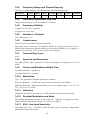
7.1 Over all Descr iption
The transmitter is a frequency synthesized, narrow band, HF/VHF, FM unit, used to
drive an external 120 watt amplifier. All necessary control and 600 Ω line interface
circuitry is included.
7.1.1
Channel Capacity
Although most applications are single channel, the T50 can be programmed for up to
256 channels, numbered 0-255. This allows a network administrator to program every
exciter, in every site, the same way. By setting each site up to select which of the 256
channels is appropriate, any exciter can be plugged into any position, in any site,
without the need to perform on-site re-programming. This can be convenient in
maintenance situations.
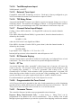
Channel information consists of two independent and complete sets of information,
which may differ or be the same. One set defines the parameters to be used, if the unit
is keyed up from PTT-in being “grounded”, and the other set defines the parameters to
be used if the unit is keyed up for any reason other than PTT-in being “grounded”.
The parameters that can be defined on a per channel basis are:
7.1.2
a)
The frequency
b)
The CTCSS tone (if any) to be generated, or, the DCS code (if any) to be
generated.
c)
The delay from the initiation of the exciter to RF output being generated
(Is specified in hundredths of a second, 0 – 999)
d)
The transmit tail; the length of time after the exciter is released before
transmission stops. (Is specified in seconds 0 – 999).
e)
The No Tone period; a length of time after the expiry of (d) in which
transmission continues, but with no tone being generated. (Is specified in
tenths of a second, 0 –999)
f)
Whether audio from Line 1, or Line 2, or both, (or neither!) is enabled,
and whether or not Pre-emphasis is required, or not, on each line, and
whether or not an extra gain pad (of 20dB) is required.
g)
What Nominal Tone Deviation, and Maximum Deviation should be used
(See Tables 7 and 8)
CTCSS
Full EIA subtone Capability is built into the modules. The CTCSS tone can be
programmed for each channel. This means that each channel number can represent a
unique RF and tone frequency combination.
7.1.3
DCS
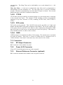
From Rev. 4 hardware and Rev. 4 firmware, support for DCS codes is supported. DCS
code generation can be enabled on a per channel basis. If enabled, the 23 bit Golay
27