1
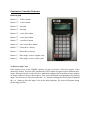
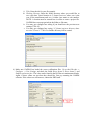
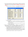
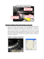
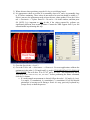
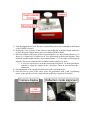
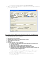
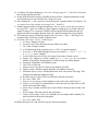
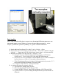
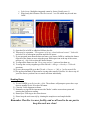
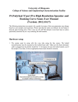
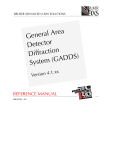
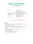
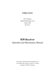
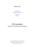
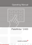
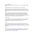
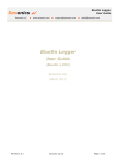
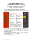
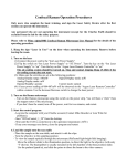
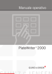
University of Minnesota
College of Science and Engineering Characterization Facility
Bruker D8 Discover User Manual
(Version: 2012.08.08)
Auto x, y, z Stage Reference
2θ (two-theta): Detector angle (GADDS angle # 1)
ω (omega): Sample / incident beam angle (GADDS angle # 2)
x: Horizontal position of sample stage (GADDS angle # 5)
y: Vertical position of stage (GADDS angle # 6)
z: Height position of stage (GADDS angle # 7)
Aux: Video microscope (GADDS angle #8)
Goniometer Controller Reference
Button legend
Button “1” – 2θ drive button
Button “2” – ω drive button
Button “3” – Not used
Button “4” – Not used
Button “5” – x axis drive button
Button “6” – y axis drive button
Button “7” – z axis drive button
Button “8” – Aux (zoom) drive button
Button “+” – Faster drive velocity
Button “-” – Slower drive velocity
Button “↑” - Drive angle / axis to a higher value
Button “↓” - Drive angle / axis to a lower value
To drive an angle / axis
Enter Manual mode in the GADDS software (see the Goniometer calibration section of the
manual for details). Press the Shift and then the DRVC button to toggle between different drive
modes. Most users prefer to select the drive mode that configures the controller screen to display
an image similar to what is shown above. Next, press the button corresponding to the desired
angle / axis to be driven. The press either the + or – button to change the velocity speed, and hold
the ↑ or ↓ button to drive the angle / axis to the desired position. The screen will update during
the driving procedure.
Initial Setup
1) Obtain a TLD ring from the ring bin found on the counter in room 22. Enter your name,
ring number, user number, sign-in time, and machine in the log book.
2) Log on to the D8 Discover computer using your x500 username and password (Domain =
AD).
a. If you are associated with the University of Minnesota, log on to the
Characterization Facility’s online reservation system. Make sure to enter your
TLD ring number, the x-ray generator counter time, and the correct budget
number.
3) Open the video microscope program Video. The software will automatically begin to
display an image.
a. Make sure that the video microscope is centered properly. In Video, select
Tools → Options and check that the origin x and y are correct. These values are
typically found in the D8 Discover maintenance binder. If these values are not
what they should be, contact the XRD laboratory staff.
4) Open the diffractometer software GADDS. There should be a desktop shortcut labeled
GADDS 3 or 4 Circle. A window will appear asking to power the generator to operating
condition (45 kV & 40 mA). Click the Yes button.
a. NOTE: Do not open the program GADDS offline to control the goniometer. This
program is useful for data analysis, but cannot control the goniometer.
5) Create a new project file (typically referred to as a gadds.nc file). This will allow you use
the most recent calibration values.
a. Go to the Special tab, select Level 2.
b. Go to the Project tab, select New.
c. Enter all relevant information in the corresponding fields (values can also be left
blank for now, except for the Working Directory field).
i. Sample Name: Enter sample name. This is associated to the filename and
cannot contain spaces or period.
ii. Title: Enter the title for your first sample.
iii. Working Directory: Enter the folder directory where you would like to
save your data. Typical location is C:\frames\year\user, where year is the
year of the measurement and user is either your name or user number.
NOTE: A location must be entered here in order to create a project file.
GADDS does not accept periods in the folder or file name.
iv. You may get a dialogue box asking if you should save the previous user
settings, Click NO.
v. You may get a dialogue box saying, “C:\frames\year\user directory does
not exist. Create it?” Click Yes and the directory will be created.
6) Make sure GADDS has loaded the correct calibration files. Go to the Edit tab →
Configure → User Settings, and check the fields Direct beam X, Direct beam Y, and
Sample to detector face. The values can be found in the D8 Discover maintenance binder.
Again, if these values are not what they should be, first try restarting the GADDS
software. If the values are still incorrect, contact the XRD staff.
7) Check to make sure that the correct software drive limits are configured. The limit values
should automatically load when creating the job file (Step 5), but due to a bug in the
software they are not always loaded. THIS IS EXTERMELY IMPORTANT TO
CHECK!!!
a. Go to the Collect tab → Goniometer → Limits and check to make sure the limit
values registered in the popup windows match EXACTLY what is shown below:
b. If the values loaded do not match the above image you have two options to
correct the problem:
i. Method 1) Delete your gadds._nc job file that was just created in Step 5,
and then create a new one. The new job file will typically have the
correctly loaded limits.
ii. Method 2) Manually input the values shown above into the Limits popup
window and then hit OK.
8) Check to see if the correct collimator is installed. For most applications the
0.8 mm collimator should be used, but smaller collimators can be installed. Please see
XRD staff for help if you are uncomfortable in changing the collimator.
a. The top thumb screw must first be loosened to remove the installed collimator.
Once loosened, the collimator tube can be removed. Be careful that you do not
bump the support structure or monochromator during this process.
b. To install a new collimator tube, the small hole on the collimator must be aligned
with the alignment pin on the collimator support structure. If properly attached,
the collimator size label should be facing upwards. The thumb screw must be
tightened such that the collimator is secured so it cannot shift or rotate.
Goniometer Calibration (Done at the beginning of each session)
1) To prepare for goniometer calibration, remove both the sample holder and the beam stop.
2) The last user may have left the goniometer in an odd configuration, so it is best to
manually move the goniometer to a safe position. Go to the Collect tab → Goniometer →
Manual mode. A window will pop up; ignore these settings and press OK. In Manual
mode, the goniometer angles can be manually driven with the control box. Select the
desired angle button and drive speed, and then press the forward or back arrow buttons
to drive the goniometer angles. Manually drive 2θ to roughly 50o and ω to roughly 10o.
Both 2θ and ω angles can be monitored by looking at the position post below the
collimator (see figure below).
3) When driven to these positions, press the Esc key to exit Manual mode.
4) It is important to check to see that 2θ is reasonably close to 50o and ω is reasonably close
to 10o before continuing. These values do not need to be exact but should be within ± 5o.
If this is not true, the goniometer needs to have the axes values updated. Go to the Collect
tab → Goniometer → Update. Enter 2θ = 50o and ω = 10o in the window, and then press
Ok. NOTE: It is important to only do this if the values reported by software are
significantly different from actual positions. Contact the XRD support staff if you feel
uncomfortable in performing this step.
5) Go to the Special tab → Level 2
6) Go to the Collect tab → Goniometer → Home axis. For most applications calibrate the
goniometer in the order: 1 (2θ angle) and 2 (ω angle). IT IS IMPORTANT TO FOLLOW
THIS ORDER! This will drive 2θ to 22.742o and ω to 7.659o. The software may ask to
“Pre-drive x & z axes to zero, are you sure?” before performing the Home command,
click the Yes button.
a. If a multi-sample measurement is desired, follow the order 1 (2θ angle), 8 (Aux),
2 (ω angle), 5 (x translation), 6 (y translation), 7 (z translation). If you feel that the
goniometer is moving too far during a Home axis step, press any keyboard key
(except Enter) to abort the process.
Sample Setup
This section contains generalized sample mounting procedures for the Microdiffractometer. For
mounting of odd sample shapes or difficult alignment configurations, it is best to consulate the
XRD support staff first.
Reflection Mode
1) Make sure the beam-stop is on the collimator if measuring at a low 2θ.
2) Drive the goniometer to the reflection alignment position: Go to the Collect tab →
Goniometer → Drive. Set 2θ = 50o, ω = 55o.
3) Put the goniometer into Manual mode. Go to the Collect tab → Goniometer → Manual,
and hit the OK button.
4) Mount the sample on the sample holder and attach it to a stage screw hole. The x axis
may need to be driven to allow for the holder to be mounted.
5) Turn the alignment laser ON. Hit the L keyboard key (notice the commands at the bottom
of the GADDS software).
6) Display the Video software. If the camera is not displaying an updated image make sure
to press the green triangle button (the Record button) in the software.
7) Move the sample to the proper position by pressing the x or y drive buttons (Button # 5 or
Button # 6, respectively) in either fast or slow speed mode to the desired location. Then
adjust the sample height with the z drive button (Button # 7). The sample will be properly
aligned if the laser is centered in the crosshairs and the sample is in focus.
a. If you can’t see the laser, zoom the microscope out (Button # 8 on the goniometer
controller), adjust the sample in the z direction. Zoom in and fine-tune the z
adjustment.
8) Fine adjustment of the z height should be done at the maximum zoom.
9) Once the laser is close to the center, move the goniometer head x and y positioning
screws to the specific area to be analyzed and readjust the z position if necessary.
Reflection mode for optically transparent films and substrates – Advanced users
1) Optically transparent films on transparent substrates can be problematic as the alignment
laser can penetrate through the substrate and reflect back towards the camera. This effect
can produce multiple laser spots at different z height positions. Alignment of the z axis to
one of these incorrect laser spots will produce shifts in the measured diffraction pattern.
There are a couple methods to align to an optically transparent film & substrate system.
2) Method 1: Align the laser to the top laser spot shown in the camera software. NOTE:
This method should only be used when the user is comfortable with the alignment
process as sometimes the top most laser spot may not be visible.
3) Method 2: Align to a piece of dust, fingerprint, scratch, or a marked structure (a Sharpie
pen spot at the corner of the sample works great). After alignment, adjust the x or y
position to move towards a region of interest to measure.
Simple scan data collection (single run or scans with only one axis movement)
1) Go to the Collect tab → Scan → Single Run.
a. # Frames: Number of scans.
b. Seconds/frame: Data collection time per frame in seconds.
c. 2θ: Center 2θ angle in frame.
d. ω: Incident beam angle, typically set to ½ of 2θ – for general analysis.
e. x: Horizontal position of sample stage in mm (entering @ will put x exactly where
you aligned it).
f. y: Vertical position of sample stage in mm.
g. x: Height position of sample stage in mm
h. Aux: Camera zoom, typically set to 6.8.
i. Scan Axis #: What angle changes between each frame (1 → 2θ, 2 → ω, 5 → x,
6 → y, 7 → z, none, coupled).
j. Frame Width: Step size of Scan Axis angle if more than 1 frame is used.
k. Mode: Step is usually used here (the Frame Width is discretely moved after each
frame).
l. Sample Osc: Option to oscillate sample in x, y, z, x & y, or y & z to increase
number of crystallites being analyzed. Useful for large crystallite samples.
m. Amplitude: Magnitude of oscillation in mm.
n. Title: Title of sample scans, sample identifier information.
o. Sample name: Copy the Title here for it to display in JADE.
p. Sample number: Another sample identifier, any number will work.
q. Job name: This is the filename and is saved to the folder set up in project file.
r. Run #: This will be added to the filename.
s. Frame #: This is added to the filename and generally is iterated with 001, 002…
t. Maximum display counts: Sets the initial max scale value for the 2D image. This
setting can be adjusted during the range.
u. Realtime display: Check YES to see the data collected in real time.
v. Pre-clear: Check YES.
w. Capture Video Image: Gives you a snapshot of your sample while scanning.
x. Auto Z align: Auto height alignment, NOT RECOMMENDED.
2) When everything is configured, check to see if the doors are closed and the reset button is
pushed. To start click OK.
For a series of scans which require moving more than one axis (Multi-run)
1)
2)
3)
4)
5)
6)
Go to the Collect tab → Scan → Edit Run.
Enter (or edit) a set of collections.
Remember the line number (s) (counting from the top line).
WRITE this set-up to your folder.
Select OK.
Go to the Collect tab → Scan → Multi-Run.
a. Job name: This is the filename and is saved to the folder set up in project file.
b. Title: Title of your run.
c. Sample name: Copy the Title here for it to display in JADE.
d. Sample number: Another sample identifier, any number will work.
e. Maximum display counts: Sets the initial max scale value for the 2D image. This
setting can be adjusted during the range.
f. Sample Osc: Option to oscillate sample in x, y, z, x & y, or y & z to increase
number of crystallites being analyzed. Useful for large crystallite samples.
g. Amplitude: Magnitude of oscillation in mm.
h. Realtime display: Check YES to see the data collected in real time.
i. Pre-clear: Check YES.
j. Sequence # of starting run: Run number to start scans with, usually set to 1.
k. Sequence # of ending run: Run number to end scans with. Leaving value to 9999
will run all scans in the listing
l. Mode: Step is usually used here (the Frame Width is discretely moved after each
frame).
m. Rotate sample: Does not work in this goniometer.
n. Capture Video Image: Gives you a snapshot of your sample while scanning. Do
not check this for the multi-scan option.
7) When done, click OK, go to the Video software and say OK to any error messages. The
run will then begin.
Multi-sample / target setup
1) To scan multiple samples it is best to either mount multiple samples on a single sample
holder, or mount multiple holders in a vertical fashion across the goniometer stage (as
seen in the image below).
2) Using Manual Mode, drive 2θ and ω to the sample alignment position (Set 2θ = 50o, ω =
55o). Be extra mindful of sample collisions!
3) Go to the Collect tab → Scan → PickTargets.
4) A window will appear displaying “Pre-clear existing target list?”, select Yes to clear out
the existing target location list.
5) In this mode the software places GADDS in Manual Mode. Align the goniometer to the
first desired target as one would do for a Single Run scan.
6) Once aligned in x, y, and z, press Esc on the keyboard. A popup window will display “Do
you want to enter this position in the targets list?”, press Yes.
7) Another popup window will appear displaying “Do you want to enter more positions in
the target list”?, press Yes if there are more samples to align, press No if this is the last
sample to align. If Yes is pressed, GADDS will be placed back into Manual mode for
alignment of the next sample. Repeat Steps 6 & 7 until all samples have been aligned.
8) The sample list can be checked by going to the Collect tab → Scan → EditTarget. An
example of the EditTarget window is shown below.
9) Go to the Collect tab → Scan → MultiTargets.
a. # Frames: Number of scans.
b. Seconds/frame: Data collection time per frame in seconds.
c. 2θ: Center 2θ angle in frame.
d. ω: Incident beam angle, typically set to ½ of 2θ – for general analysis.
e. Scan Axis #: What angle changes between each frame (1 → 2θ, 2 → ω, 5 → x,
6 → y, 7 → z, none, coupled).
f. Frame Width: Step size of Scan Axis angle if more than 1 frame is used.
g. Sample Osc: Option to oscillate sample in x, y, z, x & y, or y & z to increase
number of crystallites being analyzed. Useful for large crystallite samples.
h. Amplitude: Magnitude of oscillation in mm.
i. Title: Title of your run.
j. Sample name: Copy the Title here for it to display in JADE.
k. Sample number: Another sample identifier, any number will work.
l. Maximum display counts: Sets the initial max scale value for the 2D image. This
setting can be adjusted during the range.
m. Realtime display: Check YES to see the data collected in real time.
n. Pre-clear: Check YES.
o. Sequence # of starting run: Run number to start scans with, usually set to 1.
p. Sequence # of ending run: Run number to end scans with. Leaving value to 9999
will run all scans in the listing
q. Mode: Step is usually used here (the Frame Width is discretely moved after each
frame).
r. Rotate sample: Does not work in this goniometer.
s. Capture Video Image: Gives you a snapshot of your sample while scanning. Do
not check this for the multi-scan option.
t. Pre-clear: Check YES.
10) When done press OK, and check for any pre-run error messages.
Data Analysis
NOTE: This section describes how to convert a two dimensional diffraction pattern to an one
dimensional intensity versus 2θ data set. For more advanced data processing (i.e. texture
analysis, crystallite size, percent crystallinity, etc.), please consult the XRD staff.
1) Display the first file collected. Go to the File tab → Display → Open.
2) If you want to save the 2D image, go to the File tab → Print. Enter a filename and path
using the “…” button and select the desired image format (.bmp or .tiff recommended).
3) Integrate the 2D data. Go to the Peaks tab → Integrate → Chi.
a. Normalize Intensity: Method of integration and averaging over 2D dataset.
Usually set to 5 – Bin normalized for wide angle XRD measurements.
b. Step Size: 0.04o at 15.0 cm sample to detector distance, 0.02o at 30.0 cm sample to
detector distance, or 0.08o at 6.0 cm sample to detector distance.
c. Click OK and manually move the edges of the integration box by pressing 1, 2, 3,
and 4 on the keyboard (see bottom of screen for info).
d. Left mouse click or hit Enter to integrate the data.
4) A window will appear for saving the data set.
a. Title/SampleID: Sample name goes here.
b. Filename: Location and filename for saved data.
c. Format: DIFFRAC-Plus (for post JADE processing) or PLOTSO (ascii file).
d. Append: Check Yes if you are adding the integrated to the previous file that was
integrated.
e. Scale factor: Multiplies integrated counts by factor (Usually set to 1).
f. When ready hit Ok button. The file is now a *.raw file which may be read into
JADE.
5) Open the file in JADE as a Bruker Diffract-plus file
6) There may be a question, “File appears in cts/sec, reload with total counts?”. Select No
and select No to subsequent questions until the file opens.
7) If you measured more than one detector frame, you can use JADE to combine the frames.
Open all of the frames at once using the green folder open icon at the top of the screen,
and use ctrl + left click to select the desired frames.
8) To align all the frames use the “Drag scan overlays” option to line them up.
9) To merge the overlays together go to the Edit tab → Merge → Overlays → Take the
maximum.
10) To save the merged file go to the File tab → Save as → *.dif, or *.txt for an ascii file.
11) The preferred method of data transfer is using either email or Netfiles. It is best to zip all
your files first so you don’t have to email each item individually.
Shutting Down
1) To exit GADDS go to Project tab → Exit. The software will prompt to power the x-rays
down to standby levels. Press the OK button.
2) Close the Video alignment software.
3) Remember to sign off the instrument with Charfac’s online reservation system and
entering the final meter reading.
4) Return your TLD ring to the visitor drawer.
5) Please keep the work area tidy by cleaning the sample area and sample holder.
6)
Remember CharFac is a user facility, and we all need to do our part to
keep the work are clean!
Appendix: Troubleshooting
Adding PDF library to your version of JADE 8.0
In Jade 8.0’s drop down menu, select PDF, then setup.
A warning message will appear, select Ok.
Click on the top hand (or …) icon, browse and select C:\PDF22004\pdf2.dat.
Click on the bottom hand icon, browse and select
C:\Program Files\MDI Jade 8\pdf\jade-pdf.idx.
5) Click Close.
6) You should now be able to access the PDF library—you may get an error message, but if
you enter Ok you will be able to access the library.
1)
2)
3)
4)