1
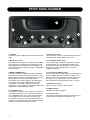
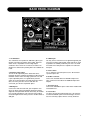
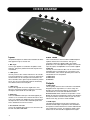
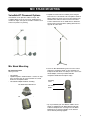
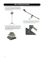
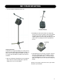
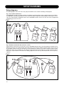
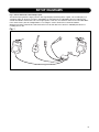
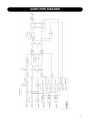
VSM-300 XT
USER MANUAL
IMPORTANT SAFETY INSTRUCTIONS
The lightning flash with an arrowhead symbol within an
equilateral triangle, is intended to alert the user to the
presence of uninsulated “dangerous voltage” within the
product’s enclosure that may be of sufficient magnitude to
constitute a risk of electric shock to persons.
The exclamation point within an equilateral triangle is
intended to alert the user to the presence of important
operating and maintenance (servicing) instructions in the
literature accompanying the product.
1
2
3
4
5
6
7
8
9
Read these instructions.
Keep these instructions.
Heed all warnings.
Follow all instructions.
Do not use this apparatus near water.
Clean only with dry cloth.
Do not block any ventilation openings. Install in accordance with the manufacturer's instructions.
Do not install near any heat sources such as radiators, heat registers, stoves, or other apparatus (including amplifiers) that produce heat.
Do not defeat the safety purpose of the polarized or grounding-type plug. A polarized plug has two blades with one wider than the other. A
grounding type plug has two blades and a third grounding prong. The wide blade or the third prong are provided for your safety. If the provided
plug does not fit into your outlet, consult an electrician for replacement of the obsolete outlet.
10 Protect the power cord from being walked on or pinched particularly at plugs, convenience receptacles, and the point where they exit from the
apparatus.
11 Only use attachments/accessories specified by the manufacturer.
12
Use only with the cart, stand, tripod, bracket, or table specified by the manufacturer, or sold with the apparatus. When a cart is used,
use caution when moving the cart/apparatus combination to avoid injury from tip-over.
13 Unplug this apparatus during lightning storms or when unused for long periods of time.
14 Refer all servicing to qualified service personnel. Servicing is required when the apparatus has been damaged in any way, such as powersupply cord or plug is damaged, liquid has been spilled or objects have fallen into the apparatus, the apparatus has been exposed to rain or
moisture, does not operate normally, or has been dropped.
Warning!
•
To reduce the risk of fire or electrical shock, do not expose this equipment to dripping or splashing and ensure that no objects filled with liquids,
such as vases, are placed on the equipment.
•
This apparatus must be earthed.
•
Use a three wire grounding type line cord like the one supplied with the product.
•
Be advised that different operating voltages require the use of different types of line cord and attachment plugs.
•
Check the voltage in your area and use the correct type. See table below:
•
•
•
•
•
Voltage
Line plug according to standard.
110-125V
UL817 and CSA C22.2 no 42.
220-230V
CEE 7 page VII, SR section 107-2-D1/IEC 83 page C4.
240V
BS 1363 of 1984. Specification for 13A fused plugs and switched and un-switched socket outlets.
This equipment should be installed near the socket outlet and disconnection of the device should be easily accessible.
To completely disconnect from AC mains, disconnect the power supply cord from the AC receptable.
The mains plug of the power supply shall remain readily operable.
Do not install in a confined space.
Do not open the unit - risk of electric shock inside.
Caution:
You are cautioned that any change or modifications not expressly approved in this manual could void your authority to operate this equipment.
Service
•
There are no user-serviceable parts inside.
•
All service must be performed by qualified personnel.
a
IMPORTANT SAFETY INSTRUCTIONS
EMC / EMI.
This equipment has been tested and found to comply with the
limits for a Class B Digital device, pursuant to part 15 of the FCC
rules.
These limits are designed to provide reasonable protection against
harmful interference in residential installations. This equipment
generates, uses and can radiate radio frequency energy and, if not
installed and used in accordance with the instructions, may cause
harmful interference to radio communications. However, there is
no guarantee that interference will not occur in a particular
installation. If this equipment does cause harmful interference to
radio or television reception, which can be determined by turning
the equipment off and on. The user is encouraged to try to correct
the interference by one or more of the following measures:
• Reorient or relocate the receiving antenna.
• Increase the separation between the equipment and receiver.
• Connect the equipment into an outlet on a circuit different from
that to which the receiver is connected.
• Consult the dealer or an experienced radio/TV technician for
help.
For the customers in Canada:
This Class B digital apparatus complies with Canadian ICES-003.
Cet appareil numérique de la classe B est conforme à la norme
NMB-003 du Canada.
Certificate Of Conformity
TC Electronic A/S, Sindalsvej 34, 8240
Risskov, Denmark, hereby declares on its
own responsibility that the following product:
VoiceSolo VSM-300XT- Active Voice
Monitor and Control
- is covered by this certificate and marked
with CE-label conforms with following
standards:
EN 60065
Safety requirements for mains
(IEC 60065) operated electronic and
related apparatus for household
and similar general use
EN 55103-1 Product family standard for
audio,video, audio-visual and
entertainment lighting control
apparatus for professional
use. Part 1: Emission.
EN 55103-2 Product family standard for
audio, video, audio-visual and
entertainment lighting control
apparatus for professional
use. Part 2: Immunity.
With reference to regulations in following
directives:
73/23/EEC, 89/336/EEC
Issued in Risskov, 10 - 2007
Mads Peter Lübeck
Chief Executive Officer
b
TABLE OF CONTENTS
Important Safety Instructions . . . . . . . . . . . .a
Certificate of Conformity . . . . . . . . . . . . . . .b
Table of Contents . . . . . . . . . . . . . . . . . . . . .3
Introduction . . . . . . . . . . . . . . . . . . . . . . . . .4
Front panel diagram . . . . . . . . . . . . . . . . . . .6
Back panel diagram . . . . . . . . . . . . . . . . . . .7
I/O box diagram . . . . . . . . . . . . . . . . . . . . . .8
Mic stand mounting procedure . . . . . . . . . .11
Making connections . . . . . . . . . . . . . . . . . .12
Overcoming feedback . . . . . . . . . . . . . . . .13
Setup diagrams . . . . . . . . . . . . . . . . . . . . .14
Specifications . . . . . . . . . . . . . . . . . . . . . .16
Audio path diagram . . . . . . . . . . . . . . . . . .17
Specifications, interface, and features are subject to change without notice due to continued product improvement
VoiceSolo VSM-300XT
English version
Rev 1.0
Prod. No: 606120091
3
INTRODUCTION
Welcome to VoiceSoloXT
The TC-Helicon VoiceSoloXT VSM range of near field live
monitoring speakers is a new concept in personal
monitoring. TC-Helicon strives for excellence in all things
related to vocals, and the VSM range builds upon the
success and worldwide reputation of TC-Helicon's vocal
expertise.
If you can't hear yourself correctly in a live situation, it's
hard to produce a good performance. VSM monitors are
designed to integrate into a boom-style microphone stand
bringing the speaker close to the performer. This yields a
wide range of benefits over existing wedge-type or in-ear
options such as:
• Lower monitor bleed into the main PA sound
• High volume level before feedback
• Better interaction with audience; stage space is
reclaimed from floor wedges and ear plug barriers are
not required as with in-ear monitors.
The VoiceSoloXT VSM monitors use a two-way point
source ICT ™ driver that eliminates the problem of hearing
separated high and low frequencies which happens when
listening to conventional speaker systems. This is
especially important when used on a microphone stand as
the speaker is located very close to the listener and the
separation would be more evident.
About TC-Helicon
TC-Helicon’s core value is that the voice is the world's
most beautiful instrument. Therefore, everything TCHelicon does is dedicated to this instrument. TC-Helicon
envisions a world where those who work with voice are
able to bring out its very best and where the possibilities
of vocal craft are endless.
The company's mission was galvanized by a simple
question, "Isn't it time that someone finally provided
dedicated tools and solutions for voice?"
TC-Helicon is revolutionizing the vocal channel by
providing innovative tools and solutions for people who
create and work with the speaking and singing voice.
Our customers include the most demanding of live
performers, producers, broadcasters and recording
engineers.
Enjoy!
Features:
• Improved high frequency response in the critical 4 to 10
kHz range resulting in higher accuracy and smoother
sound.
• Quick mic stand set up. Integrates with boom so the
same stand is used for the monitor and microphone.
• Versatile placement options provided by dual stand
mounting holes and dual bevelled edges for floor
mounting.
• Two-way point source 6.5" ICT™ driver for optimal nearfield live monitoring.
• High volume capability: 116dB peak SPL at .5m
• 150W BASH amplifier.
• Cast aluminum enclosure for maximum rigidity and
minimum cabinet resonance
• Front panel mounted controls for easy access.
• External IO box interfaces with instruments, aux mixes
• Microphone preamp, stereo line and aux inputs.
• Phantom power on mic input
• Pass thru to house mixer on all inputs
• Mic Level, line level and master level controls.
• Shape EQ control on Mic input, plus 18dB/octave 75hz
Low Cut Filter.
• Selectable 75Hz/150 18dB/Octave Low Cut Filter on
Speaker output mix
• Selectable Mono/Stereo operation for line input
• Output for active subwoofer
4
The TC-Helicon Team
a TC Group company
INTRODUCTION
Preliminary Recommendations
The VoiceSoloXT VSM series of monitors are capable of
very high sound pressure levels (SPLs) especially at the
close range when integrated onto a microphone stand.
They were designed this way to be able to be loud enough
to compete with live acoustic drum kits. In situations where
high monitoring volumes are required we recommend that
ear protection be used.
For continuous exposure we recommend the occasional
use of a sound level meter capable of measuring the sound
level over a period of exposure according to noise control
standards. This should be used to check that noise levels
are always within safety limits.
Unpacking
Open the box from the top and remove cabling and IO box
(VSM-300XT only). Lift out Styrofoam insert, then using
both hands lift out VoiceSoloXT. Remove plastic bag from
VoiceSoloXT. Nothing in your speakers should rattle.
Inspect each speaker for signs of transit damage. In the
unlikely event of this having occurred inform the carrier and
the supplier. Keep all the packaging if damage has
occurred, as this will show evidence of excessive handling
forces. It is also a good idea to keep the packaging if
possible for future transportation.
Registering VoiceSoloXT
There are two methods for registering your VoiceSoloXT:
• Online: visit www.tc-helicon.com/VoiceSolo and click
Product Registration in the left hand column.
• Mail: complete and return the registration card included
with your product
Support
If you run into technical challenges, TC-Helicon will be
more than happy to help. There are a number of sources
for product support. We've prioritized them below according
to the speed at which you will access the help information.
1. Manual: The manual for VoiceSoloXT VSM-300XT is
extensive. It's a good source of application information
and in depth answers for common questions.
3. On-Line: visit www.tcsupport.tc to search and ask for
answers on up to date questions about VoiceSoloXT.
4. Phone:
International: +45 8742 7000
USA & Canada: 818-665-4900
5
FRONT PANEL DIAGRAM
10
1
9
2
4
5
6
3
8
7
1. CLIP LED
This LED is a sum of clipping from the MIC, LINE and AUX
inputs.
5. LINE IN level control
This sets the gain for the line input. Adjust this so that only
the loudest notes you play light the CLIP LED.
2. MIC IN level control
This control trims the gain for the microphone input. Adjust
this so that only the loudest notes you sing light the CLIP
LED periodically. If you find the CLIP LED is lighting even
with the MIC IN control at minimum, push the +20dB button
to the out position.
6. The LOW and HI EQ controls
These are basic high (12 kHz) and low (80 Hz) frequency
shelving controls. They can add warmth and bite to the
monitor sound which can be desirable. Be aware though,
that too much of either at loud volumes can result in
feedback or distortion.
3. MONO / STEREO switch
This switch expands the capabilities of two VoiceSoloXTs
when operation as a stereo PA is desired. When the stereo
option is chosen (switch in), an audio signal received at the
RIGHT input on the I/O box is passed to another
VoiceSoloXT from the MIX output jack. The audio signal
received in the LEFT input is produced from the main
VoiceSoloXT. The OUTPUT control on the main unit
controls both levels. Choosing the mono option (switch out)
collapses the left and right inputs to mono.
7. The 75/150 Hz LOW CUT button
A low frequency filter is always engaged on VoiceSoloXT to
preserve amplifier power and to protect the speaker. You
have your choice of 75 Hz (switch out) which allows some
low frequency to be reproduced, or 150 Hz (switch in)
which rolls off low end to allow higher volume if required.
4. The SHAPE control
This imposes a useful tone curve onto the MIC IN input. It
is intended to simulate the tone of a studio condensor mic
from a standard dynamic mic. It is not recommended for
use with bright mics such as condensers because too
much high frequency may result. At minimum position, the
SHAPE circuit is defeated and the mic is heard flat, at fully
clockwise, the SHAPE circuit is fully activated.
6
8. OUTPUT level control
This is the master control for all of the inputs.
9. POWER indicator
This lights when power is applied.
10. Tuned bass port
This enhances VoiceSoloXT’s output of low frequencies. It
is also useful as a handle when carrying the unit.
BACK PANEL DIAGRAM
1
6
2
4
3
5
8
1. +20 dB button
The +20 switch, when pushed in, adds more gain to your
dynamic mics that may produce lower output. When the
switch is out, it is possible to connect high output
condenser mics or some line level devices. Reduce the
Output level control before pushing this in as feedback can
result.
2. Phantom power button
The Mic in has a phantom power switch that can be
pushed in to power condensor microphones. Otherwise this
should be left out. Before inserting a jack from a mic that
requires phantom power, it’s a good idea to push the
switch so it is out and power is turned off and once that’s
done, insert the jack. Once the mic and cable are
connected, you can turn on phantom power.
3. MIC IN jack
Connect the XLR connector from your microphone here
when you will be using VoiceSoloXT without the I/O box.
Adjust the front panel MIC IN knob so that only the loudest
note you will sing lights the red CLIP LED. If the loudest
notes don’t light the CLIP LED, press the +20 dB switch to
add gain.
4. LINE IN jack
You may connect a mono line level signal through this jack
such as an acoustic guitar pickup, guitar multi-effect, mono
keyboard or an auxilliary send from your mixer. The LINE
IN control on the front panel is a separate mix control for
this input.
5. Power switch
The “|” character represents power on, the “O” character
represents power off.
6. I/O Box connector
Connect the included cable from this DB15 input to the
same connector on the I/O box for additional inputs and
outputs.
7. AC power input
Connect the standard IEC power cable that is included with
VoiceSoloXT here.
8. Fuse holder
The power amp is protected with this fuse. If the switch is
on and VoiceSoloXT’s power LED will not light, check the
fuse here and only replace with the correctly rated fuse.
7
I/O BOX DIAGRAM
6
7
8
9
10
11
7
1
2
3
4
5
Inputs
Pass Thrus
All inputs and outputs are balanced but unbalanced cables
and equipment may be used as well.
These connections are used to send the individual inputs to
separate channels in an external mixer. This type of
connection is known as a passive splitter. The signals
produced here are exact duplicates of signals received at the
respective inputs; no amplification or level control is applied.
6. MIC thru
This may be connected to the Mic In on an external mixer.
If phantom power is activated on the external mixer or is
non-defeatable, ensure that the phantom power switch on
VoiceSoloXT is in the out position.
7. LINE 1 thru
8. LINE 2 thru
9. AUX thru
1. MIC input
Connect your dynamic or condensor microphone to this
XLR jack. This jack is parallel with the MIC IN jack on the
VoiceSoloXT.
2. LINE input 1
You may connect either a mono instrument or the left side
of a stereo signal source to this 1/4” jack. The mono/stereo
function switch is on the front panel of VoiceSoloXT. You
will need another active (powered) VoiceSoloXT to produce
stereo. The mix level of both LINE inputs is controlled by
the LINE IN control on the front panel.
3. LINE input 2
Connect the right side of a stereo signal source here.
When the front panel mono/stereo switch is set to mono,
this input is summed with the left LINE input.
4. AUX input
This is an additional mono input. This would typically be
used to receive a monitor mix or instruments from a mixer.
There is no separate mix adjustment on the front panel for
this input like there is for the MIC and LINE inputs so the
source should have its own level control.
5. VoiceSoloXT connector
Connect the supplied DB15 cable here to connect the I/O
box with VoiceSolo VSM-300XT.
8
Outputs
10. MIX output
This is typically used to feed a second active VoiceSoloXT,
designated as the right channel, in a stereo setup. The
OUTPUT level and the EQ settings on the front panel of
VoiceSoloXT are sent to both VoiceSoloXTs and the
MONO/STEREO switch controls stereo operation. If set to
MONO, the MIX out could also drive another VoiceSoloXT’s
line input so another musician could hear your voice and
instrument the way you have it mixed and EQ’d.
11. SUB output
This output is intended to feed an active sub woofer. It is
similar to the MIX output except that the LEFT and RIGHT
line inputs are summed and sent here and the EQ and LOW
CUT controls have no effect. The OUTPUT control sets the
master level. No Low Pass filter is applied on this output.
MIC STAND MOUNTING
VoiceSoloXT Placement Options
VoiceSoloXT can be placed in 4 different ways. This
versatility allows you to use it as a mic stand mounted
monitor one night, a PA system on another and then use it
at home for practice or jamming.
1. Separate the boom from the stand by unscrewing the
boom from the vertical shaft of the microphone stand. To
do this, tighten the clutch you use to raise and lower the
stand first. This makes it easier to unscrew the boom
section. Hold the base of the stand with one hand and
turn the boom counterclockwise (looking down from the
top) with the other hand.
Mic Stand Mounting
Mic Stand Integration
What you need:
• VoiceSoloXT
• Tripod microphone stand with boom - must be the style
where the boom may be unscrewed from the vertical
shaft of the microphone stand.
• VoiceSoloXT adaptor hardware including:
Mic Boom Mount Attachment
2. Screw the Mic Stand Mounting Insert on to the vertical
shaft of the microphone stand. (If your stand has 3/8",
European thread it will be necessary to use a 5/8" to 3/8"
thread adapter, commonly included with both
microphone stands and microphone clips)
Mounting
Insert
Mic Stand
Shaft
Mic Stand Mounting insert
* Tip: If you find that your VoiceSoloXT wobbles on the
stand, try wrapping the Mic Stand Shaft threads with
Teflon thread tape before screwing on the Mic Stand
Mounting Insert. Teflon thread tape can be found at
stores that sell plumbing supplies.
9
MIC STAND MOUNTING
3. Place VoiceSoloXT on the mic stand so the stand goes
into the hole on the bottom of the VoiceSoloXT. If you
don’t need to mount VoiceSoloXT on a boom stand, you
are finished with your setup. If you require the boom,
continue to the next step.
5. Screw the Mic Boom Mount Attachment into your boom.
6. Lift the lid on VoiceSoloXT, and while holding it open,
slide the Mic Boom Mount attachment, on the boom into
slot on top of the monitor and let the lid close.
4. The Mic Boom Mount is found in the bag of parts that
came with your VoiceSoloXT. There are two versions: a
thin one for European stands and a wider one for the
rest. This adapter connects the boom of your mic stand
with VoiceSoloXT. It is designed to fit into the top
receptacle in VoiceSoloXT.
10
MIC STAND MOUNTING
7. Your VoiceSoloXT should now look like this.
2. Still holding the boom so that it does not swing away,
turn the lock nut counter-clockwise until it’s snug against
the bottom of the boom. Note that it’s not possible to
completely tighten the lock nut with your fingers, the final
action is done by swinging the boom snug against the
lock nut.
Adjusting the Boom
To optimize line-of-sight and audibility it is usually better to
have the monitor situated somewhat beside the singer. To
do this it is necessary to adjust the position of the boom.
The steps required to adjust the position of the boom are
as follows:
1. With the VoiceSoloXT integrated into the mic stand and
boom, loosen the boom by rotating to the right while
holding onto a corner of VoiceSoloXT.
3. After tightening the lock nut with your fingers, swing the
boom left, tightening to the desired position. It may be
necessary to go through steps 1 - 3 a few times to get
the boom tightly where you want it. The boom must be
tight or the weight of the mic can cause it to swing out of
position.
Read the next section to learn how to connect your cables
and power up VoiceSoloXT.
11
MAKING CONNECTIONS
Introduction
The following paragraphs should be read at least once to
learn more about safe and successful use of VoiceSoloXT.
Hooking up AC power
the OUTPUT level first then raise it carefully. You’re now
ready to perform with VoiceSoloXT!
Using the I/O (Input and Output)
connector box
IMPORTANT - Before connecting the AC cable, confirm
that the power specifications printed above the power input
connector are correct for your area. VSM powered
monitors do not feature automatic AC switching which is
due to the high power to size ratio of BASH amplifiers.
Why do I need a separate box for connections?
The I/O box becomes necessary when you want to connect
to, or to create, a PA system from VoiceSoloXT.
When you have confirmed that the AC standard is correct,
turn the Power switch on VoiceSoloXT OFF and then plug
the supplied AC cable from the input on VoiceSoloXT to a
power receptacle.
• It allows the VSM-300XT to be a versatile hub with more
inputs and outputs.
• It also offers stereo capability when you add another
active VoiceSoloXT.
• The I/O box is the key to retaining local control of your
monitor mix and level while feeding a PA.
Good audio practice suggests that you always turn the
front panel Output level all the way down before switching
on power with the power switch.
Now, apply power with the On/Off switch. The POWER
LED on the front panel will glow. If it doesn’t, check that the
power source from the wall is good and that the power
cable to VoiceSoloXT is connected tightly.
Using the Onboard Mic and Line
inputs
The VSM-300XT can be used with or without the included
I/O box. The Mic and Line input connectors on the monitor
itself allow it to be used without the I/O box for music
reinforcement or public address. See the Setup Diagrams
section later in this manual for hookup possibilities.
Before connecting audio cables
Turn the front panel OUTPUT control so the level is off and
set the LOW and HI EQ controls to 12 O’clock (straight up).
Leave the LOW CUT switch out.
Plug in your mic
If your mic is phantom powered, push the Phantom switch
in after you’ve connected your mic. Adjust the front panel
MIC IN knob so that only the loudest note you will sing
lights the red CLIP LED. If the loudest notes don’t light the
CLIP LED, press the +20 switch to add gain.
Plug in your instrument
You can adjust the mix level of this instrument with the
LINE IN control once you’ve raised the OUTPUT level. If
the CLIP LED lights while playing your instrument, lower
the LINE IN level or reduce level from the instrument.
Making adjustments
Now raise the OUTPUT level slowly while you sing or say
“check” into the mic. Once this level is good, you can
adjust the LINE IN level to taste. Now that the levels are
balanced, you can balance your vocal tone with the
SHAPE control and the overall tone with the EQ controls.
As always, when making adjustments, especially EQ, lower
12
With typical monitor systems, you run your signal sources
(vocal mic, guitar, cd player) to a mixer on the other side of
the stage and request changes or run over and do them
yourself away from your monitor. The VoiceSoloXT
difference involves connecting your sources directly to the
VSM-300XT, mixing them locally while at the same time
passing them on unmixed to the PA mixer for your
audience to enjoy. This is only one scenario, there are
others discussed in the Setup Diagrams section later in the
manual.
First
Follow the instructions in the Hooking up AC Power section
at the top of this page.
Before connecting audio cables
Turn the front panel OUTPUT control so the level is off and
set the LOW and HI EQ controls to 12 O’clock (straight up).
Leave the LOW CUT switch out.
Connect the supplied multipin cable
This cable has male and female jacks that only fit into the
respective jacks on VoiceSoloXT and the I/O box.
Plug in your mic
Connect your mic to the MIC input on the I/O box or
VoiceSoloXT itself. If your mic is phantom powered, push
the Phantom switch on VoiceSoloXT after you’ve
connected your mic. Adjust the front panel MIC IN knob so
that only the loudest note you will sing lights the red CLIP
LED. If the loudest notes don’t light the CLIP LED, press
the +20 dB switch to add gain.
Plug in your instrument
You may connect a mono instrument to LINE LEFT
(MONO). If you have a stereo instrument or signal source
such as a music player, connect it to the LINE LEFT and
RIGHT inputs. You can adjust the mix level of the line
input(s) with the LINE IN control once you’ve raised the
OUTPUT level. If the CLIP LED lights while playing your
instrument, lower the LINE IN level or reduce level from the
instrument.
MAKING CONNECTIONS
Plug into the Aux Input
If you would like to blend your mic and instrument with, for
example, a signal from another musician, a monitor send
from a mixer, or even a MIX output from another
VoiceSoloXT, connect it to the AUX input.
Connect Pass Thrus
If you will be interfacing the VSM-300XT to an external
mixer, connect a cable from the pass thru jack that
corresponds to any inputs you have connected, for
example a microphone and instrument, to individual
channels on your PA mixer just as you would if
VoiceSoloXT was not in the system. Adjusting levels and
EQ on the VoiceSoloXT will have no effect on these signal
paths so that the house PA mix can be EQ’d and mixed
fully separately.
Using the MIX output
If you plan on building a stereo monitor system or PA,
connect the MIX output to another VoiceSoloXT which will
become the right speaker. You will need to adjust the level
of the second VoiceSoloXT so that it is balanced with the
left, or main VoiceSoloXT. From then on, the OUTPUT
control on the main unit controls the overall volume. If you
are sending your mix to another musician so they can hear
you, set the MONO/STEREO switch to MONO so they can
receive a sum of the left and right LINE inputs.
Connecting a subwoofer
An active (powered) subwoofer can extend low frequencies
for richer monitoring or small PA sound. Connect a cable
from the SUB output to the input of the subwoofer. The
MONO/STEREO switch has no effect on this output but the
OUTPUT control does control level.
Making adjustments
If you’ve waited until now to raise the OUTPUT level, do so
slowly while you sing or say “check” into the mic. Once this
level is good, you can adjust the LINE IN level to taste.
Adjustment of the signal source received at the AUX input
has to be done externally. Now that the levels are
balanced, you can balance the tone of your mic with the
SHAPE control and adjust the overall tone with the EQ
controls. As always, when making adjustments, especially
EQ, lower the OUTPUT level first then raise it carefully.
You’re now ready to perform with VoiceSoloXT!
Overcoming feedback
As in any open speaker and mic combination, there is the
threat of feedback. For those who aren’t familiar with the
term, “feedback” describes the sudden shriek or howl that
happens when a mic hears the speaker’s sound and
amplifies it. The following tips should help you to minimize
the risk.
• Always raise the volume level slowly, singing something
into the mic as you do so. Feedback will give you a little
warning if you listen carefully. When you hear a slight
ringing while you check the mic, lower the level a little
and this will become your “safe” monitoring level.
• Be careful when boosting EQ beyond the 12 O’Clock
position on the controls. This is especially true of adding
highs. You should lower the level a small amount first
when boosting EQ. Note that adding EQ is like turning
up the volume in a limited frequency range so reducing
the volume when adding EQ isn’t like making your
monitor quieter.
• Add SHAPE EQ in small, gradual amounts as you sing
and test for feedback. SHAPE adds highs while cutting
mids and lows so, at high SPL levels it may cause
feedback.
• Consider your placement. When VoiceSoloXT is slightly
off to one side as opposed to directly in front of you, you
will hear it better and can hear well with less level. Side
placement is also optimal when using mics with a hypercardioid pickup pattern because, in exchange for
reduced sensitivity at the back-sides of the mic, there is
more sensitivity directly at the back of the mic.
• When using handheld mics near VoiceSoloXT never
point the mic at the speaker. This seems obvious yet it
happens all the time.
• When your mic is connected to a mixer and VoiceSoloXT
is fed by a monitor send, ensure that the monitor send is
Pre-EQ. This allows you to add EQ to the main PA
sound on your channel but to send a flat (no EQ) signal
to VoiceSoloXT. With a good mic and a strong singer, a
flat monitor is likely to be louder than an EQ’d one.
A note about maximizing output volume
For maximum output volume, set the OUTPUT knob to
max and adjust the MIC and LINE knobs until the CLIP
LED occasionally flashes. If the MIC control is at max and
the CLIP LED does not flash with a loud input, turn down
the MIC knob, press in the +20dB switch on the back panel
and then re-adjust the MIC knob. Be sure to first turn
down the MIC knob before pressing the +20dB button;
adding 20dB abruptly will likely result in feedback.
13
SETUP DIAGRAMS
Setup diagrams
The following figures show a few of the many ways VoiceSoloXT can be used for monitoring or PA purposes.
Fig. 1: The common monitor mix
In this application you will use a single monitor mix containing several input sources from a mixing console as the input to
the VSM-300XT. This allows all performers to hear each other and this helps with vocal blending. In this setup, there is no
“more me” control because changing the volume of the VSM-300XT will raise or lower the entire mix at once as opposed to
emphasizing your voice in the mix.
Fig. 1
Fig. 2: Common monitor mix with “more me” control
Each performer connects their mic to the Mic In on the VSM-300XT and then thru to the PA. Normally, this would mean no
ability to hear others in the monitor but this connection scheme also is fed by a monitor send from the PA. The key is to get
an acceptable monitor mix from the external mixer to VoiceSoloXT first, setting the level with the LINE IN control on VSM300XT. Once this is set, it’s possible for each performer to raise their own mic level above the rest with the MIC IN control.
This scheme requires that the external mixer be analog; digital mixers have latency which would cause uneven frequency
response.
Fig. 2
14
SETUP DIAGRAMS
Fig. 3: Stereo PA/monitors with multiple inputs
This small setup is good for a single performer who sings and plays to backing tracks. A guitar, a stereo MP3 player (or
equivalent) and a mic all can be sent to the VSM-300XT. The MIX output of the VSM-300XT drives the LINE IN of the
second VoiceSoloXT which becomes the stereo right speaker. In this case, the OUTPUT control on the main VSM-300XT
is the master volume (after the left/right balance is set using the volume control of the second VoiceSoloXT.
Optional connections could include a sub-woofer driven from the Sub Out on the I/O box or individual pass thrus to a
recording mixer or PA.
Fig. 1
XT
XT
15
SPECIFICATIONS
Audio Inputs
All inputs and outputs are balanced
(Onboard)
¼-inch Line input
XLR with 42VDC phantom power and switchable sensitivity
range 0db/+20db
(I/O connector box)
¼-inch Line input (Left/Mono)
¼-inch Line input (Right)
¼-inch Aux input
XLR Mic input with 42VDC phantom power
Sensitivities:
Mic input - (+20 dB switch out) +4 dBu to -23 dBu
(+20 dB switch in) -16 dBu to -43 dBu
Line input - +20 dBu to -13 dBu
Audio Outputs
¼-inch Mix output (Slaves to Output level and EQ)
¼-inch Sub output (Slaves to Output level only)
¼-inch Line thru (Left/Mono)
¼-inch Line thru (Right)
¼-inch Aux thru
XLR Mic thru
Power Amp
150 watts BASH® technology into 4 ohms (200 watts peak)
Distortion: 0.5% @ 150W; 10% @ 200W
Frequency response: 75 Hz–20 kHz
EQ
Low: ± 10 dB @ 120 Hz
High: ± 10 dB @ 15 kHz
“Shape” (mic input only) complex curve
Speaker
Speaker: 6.5 inch patented ICT custom-designed point
source driver includes inductively coupled tweeter
Nominal impedance: 4 ohms
120 Watt Program / 240 Watt Peak power handling
Conical dispersion: 90 degrees
Frequency response: 120 Hz – 20 kHz
Peak SPL: 116 dB @ .5 meter
Case
Enclosure: molded aluminum with integral bass port
Color: Black
Dimensions
(H x W x D): 9” x 7” x 9.75”
(23 cm x 18 cm x 25 cm)
Shipping weight: 12 lbs. (5.5 kg)
Net weight: 10.8 lbs. (4.9 kg)
AC
Three non-interchangeable units:
220-240 VAC ~60 Hz 1.2A Fuse: T1.25AL 250V
120 VAC ~60 Hz 2A Fuse: T2AL 250V
100 VAC ~50/60Hz 2A Fuse T2AL 250V
16
AUDIO PATH DIAGRAM
17