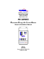
1
INCORPORATED 4282 Reynolds Drive Hilliard Ohio, 43026 1(800) ACPOWER www.vanner.com RE SERIES Renewable Energy AC Control Module Owner’s/Installation Manual AC LOADS L1 AUTOMATIC UTILITY MANUAL GENERATOR AC SELECTOR L2 POWER GROUP AC Control Module INVERTER BYPASS & DISCONNECT BYPASS SWITCH LOGIC A B POWER ON OFF UTILITY OFFON AC DISCONNECT L2 L1 INVERTER OFFOFF OFF A B A B AC INTERRUPTION / POWER DISTRIBUTION RE24-ACM Model RE-ACM Owners Manual #D910272 07/09/01 5:31 PM INCORPORATED Owner's/Installation Manual Notes: 2 Copyright 2001 Vanner Inc. 4282 Reynolds Dr. Hilliard Ohio 43026 Phone: (614) 771-2718 FAX: 614-771-4904 www.vanner.com RE-ACM-Owners_Man_R01a.doc RE-ACM Owners/Installation Manual Rev 0.1a INCORPORATED Table of Contents TABLE OF CONTENTS 1 INTRODUCTION............................................................................................................................................... 5 2 SPECIFICATIONS AND FEATURES............................................................................................................. 6 AC Transfer Switch..............................................................................................................................................................7 2.1 2.2 3 SAFETY INSTRUCTIONS ............................................................................................................................... 9 3.1 3.2 3.3 3.4 4 STANDARD FEATURES ................................................................................................................................... 8 PARTS AND ACCESSORIES .............................................................................................................................. 8 SAFETY INSTRUCTIONS........................................................................................................................ 10 GENERAL PRECAUTIONS .............................................................................................................................. 10 EXPLOSIVE GAS PRECAUTIONS .................................................................................................................... 11 CODE COMPLIANCE ..................................................................................................................................... 11 COMPONENT IDENTIFICATION ............................................................................................................... 12 (1) KNOCKOUT ENTRY/EXIT FOR HIGH CURRENT DC WIRING ............................................................................. 13 (2) KNOCKOUT ENTRY/EXIT FOR LOW CURRENT DC WIRING AND CONTROL WIRING ......................................... 13 (3) KNOCKOUT ENTRY/EXIT FOR AC WIRING AND RACEWAY .............................................................................. 14 (4) DC RACEWAY.................................................................................................................................................. 14 (5) AC RACEWAY.................................................................................................................................................. 14 (6) MOUNTING BOLT SLOTS .................................................................................................................................. 15 (7) AC SELECTOR SWITCHES................................................................................................................................. 15 (8) AC DISCONNECT ............................................................................................................................................. 15 (9) INVERTER BYPASS CIRCUIT BREAKERS ........................................................................................................... 15 (10) AC LOAD CIRCUIT BREAKERS..................................................................................................................... 15 (11) CHASSIS GROUND TIE POINT ......................................................................................................................... 15 5 INSTALLATION AND START-UP ............................................................................................................... 16 5.1 5.2 5.3 5.4 INSTALLATION AND START-UP ..................................................................................................................... 16 AC UTILITY/LOAD WIRING INSTALLATION PROCEDURE ............................................................................. 17 DC RACEWAY WIRING INSTALLATION PROCEDURE.................................................................................... 19 FINAL INSPECTION ....................................................................................................................................... 20 6 PREVENTIVE MAINTENANCE AND TROUBLE SHOOTING PROCEDURES.................................. 21 7 APPENDIX........................................................................................................................................................ 22 7.1 7.2 7.3 WARRANTY ................................................................................................................................................. 22 APPLICATION NOTES ................................................................................................................................... 23 APPLICABLE DOCUMENTS ........................................................................................................................... 23 3 Copyright 2001 Vanner Inc. 4282 Reynolds Dr. Hilliard Ohio 43026 Phone: (614) 771-2718 FAX: 614-771-4904 www.vanner.com RE-ACM-Owners_Man_R01a.doc RE-ACM Owners/Installation Manual Rev 0.1a INCORPORATED Table of Contents List of Tables T 1 TABLE 2.0-1 RE-ACM AC CONTROL MODULE SPECIFICATIONS ......................................................................... 7 List of Figures F 1 FIGURE 2.0-1 AC CONTROL MODULE ................................................................................................................... 6 F 2 FIGURE 4.0-1 AC CONTROL MODULE FRONT AND SIDE VIEW ............................................................................ 12 F 3 FIGURE 4.0-2 AC CONTROL MODULE SCHEMATIC .............................................................................................. 13 F 4 FIGURE 4.0-3 DC RACEWAY TERMINATIONS ...................................................................................................... 14 F 5 FIGURE 4.0-4 AC RACEWAY TERMINATIONS ...................................................................................................... 15 F 6 FIGURE 5.2-1 ACM SCHEMATIC.......................................................................................................................... 17 F 7 FIGURE 5.2-2 ACM AC RACEWAY CONNECTIONS............................................................................................... 18 F 8 FIGURE 5.2-3 RE-ACM TO RE-4500 AC INTERCONNECTIONS ........................................................................... 18 F 9 FIGURE 5.3-1 ACM DC RACEWAY CONNECTIONS............................................................................................... 19 F 10 FIGURE 5.3-2 RE-4500 TO RE-ACM DC CONNECTIONS ................................................................................... 20 4 Copyright 2001 Vanner Inc. 4282 Reynolds Dr. Hilliard Ohio 43026 Phone: (614) 771-2718 FAX: 614-771-4904 www.vanner.com RE-ACM-Owners_Man_R01a.doc RE-ACM Owners/Installation Manual Rev 0.1a INCORPORATED 1 Introduction INTRODUCTION Thank you for purchasing a Vanner RE-4500DGT Renewable Energy Inverter System. We are confident that you will be satisfied with its performance and its many features. With proper installation and care, you can look forward to years of service from this high performance product. “RE-ACM” stands for Renewable Energy System AC Control Module. The RE Series AC Control Module is a control system designed to incorporate the AC breaker, wiring, and switching needs for connecting the RE-4500DGT to utility, inverter, generator, and load. This document will describe the operation, technical specifications and installation procedures of the REACM and accessories offered in this product family. We suggest that you acquaint yourself with the RE4500 inverter/charger and other optional accessories before proceeding with this manual. If you require additional information please contact your dealer, or contact us directly at 1-800-227-6937 (800 AC POWER). WARNING: Before you install and use your RE-ACM, be sure to read and save these safety instructions. WARNING: The RE-ACM is not designed to be a part of Life Supporting or Life Sustaining Equipment. If the Unit is to be used in such an application, please contact Vanner Inc. at 1-800-ACPOWER. The RE SERIES product line is designed to meet the requirements of a variety of applications. SAVE THESE INSTRUCTIONS! Please note your model and serial number here for future reference. Model No.________________ Serial No.________________ Date of Installation ______________ This document describes the operation, technical specifications and installation procedures for the REACM AC Control Module System. If you require additional information please contact your dealer or contact Vanner at 1-800-AC POWER (1-800-227-6937). 5 Copyright 2001 Vanner Inc. 4282 Reynolds Dr. Hilliard Ohio 43026 Phone: (614) 771-2718 FAX: 614-771-4904 www.vanner.com RE-ACM-Owners_Man_R01a.doc RE-ACM Owners/Installation Manual Rev 0.1a INCORPORATED 2 Specifications and Features Specifications and Features The block diagram shows the components of the RE-ACM system. F 1 Figure 2.0-1 AC Control Module AC Control / Distribution Module Inverter L1 N Utility Meter L1 N L2 L1 N L2 L2 Inverter Bypass Inverter Bypass Optional Components Generator Option Only Main AC Disconnect AC Source Transfer Relay Generator Run To AC Loads Manual Utility Start Automatic Generator Neutral Inverter Control 6 Copyright 2001 Vanner Inc. 4282 Reynolds Dr. Hilliard Ohio 43026 Phone: (614) 771-2718 FAX: 614-771-4904 www.vanner.com RE-ACM-Owners_Man_R01a.doc RE-ACM Owners/Installation Manual Rev 0.1a INCORPORATED Specifications and Features T 1 Table 2.0-1 RE-ACM AC Control Module Specifications AC Power Output Rated Output Watts (-40 to +40°C) Continuous Output at 25°C (77°F) Continuous Output at 40°C (104°F) Max Continuous Output on L1 or L2 3 Second Surge Output (at 24 VDC input, and 25ºC) AC Maximum Output Fault Current Output Voltage, Single Phase, 3 Wire Output Frequency AC Output Wiring Method AC Transfer Switch Amperage Rating Output Neutral to Ground System Generator Start & Low Battery Warning Control Relays Rating Ambient Operating Temperature Enclosure Dimensions Unit Weight 4500 Watts 4500 Watts 3650 Watts 26.5 Amps (Electronically current limited by RE-4500) 10000 VA 56.25 Arms (Inverter shuts down in 1/60 sec) 120/240 Vrms \ 60 Hz Hardwire Terminal Strip 30 Amp 240 Volt Not Bonded 5 Amps 120 VAC / 12VDC / 24 VDC (Resistive load) -40° to +40°C (-40 to +104°F) Painted Aluminum for Wall Mounting TBD H x TBD W x 9¼ D TBD pounds 7 Copyright 2001 Vanner Inc. 4282 Reynolds Dr. Hilliard Ohio 43026 Phone: (614) 771-2718 FAX: 614-771-4904 www.vanner.com RE-ACM-Owners_Man_R01a.doc RE-ACM Owners/Installation Manual Rev 0.1a INCORPORATED 2.1 Specifications and Features Standard Features 1. Includes most requirements for utility, load, bypass, and AC generator connections, breakers, and switches in a convenient assembly. 2. Eliminates “box clutter” caused by normal integration of Utility, AC Generator, and load Circuit Breakers. 3. Slotted mounting holes allow easy mechanical integration. 4. Entry/exit knockouts allow easy integration (no conduit required) to interface to RE-4500 and REDCM. 2.2 Parts and Accessories Part Number Name Description RE-4500 Inverter/Charger Includes the Grid Tied Inverter Charger electronics. This intelligent system provides grid-tied Interactive power from a DC Source. This system also provides power to charge the system’s Batteries to provide AC power when Solar or Utility is not available. RE-ICC/LCD RE-ICC Remote Inverter Charger Remote Controller – changes programmable settings inside the RE-4500. RE-DCM DC Control Module Includes most requirements Solar, Battery, Auxiliary DC Loads, Charge Controllers, Disconnects, and connections for the DC source and loads in a convenient assembly. 8 Copyright 2001 Vanner Inc. 4282 Reynolds Dr. Hilliard Ohio 43026 Phone: (614) 771-2718 FAX: 614-771-4904 www.vanner.com RE-ACM-Owners_Man_R01a.doc RE-ACM Owners/Installation Manual Rev 0.1a INCORPORATED 3 Important Safety Precautions SAFETY INSTRUCTIONS Warning Labels Please READ ME SAVE THESE SAFETY INSTRUCTIONS! It should be noted that hazardous voltages are associated with this product. This unit has connections to AC at lethal amperages and voltages. Installation should only be done by qualified personnel and in compliance with local regulations and codes. Special care must be taken in working around the RE-ACM System in order to avoid hazardous voltages and currents. Note: In order to reduce the risk of damage to personnel or equipment, please read all instructions in this manual, particularly warnings noted by the following symbols. These symbols are used to note procedures that if not closely followed could lead to loss of life or damage to equipment or property due to electrocution. Electrocution Hazard Exists Fire Hazard Exists A Potential Dangerous Condition AC - This symbol denotes AC Voltage is potentially present on this termination. L1 Phase 1 - This symbol denotes that this termination is used for the upper phase of a 240 Vrms 3 wire system consisting of Phase 1 (Black wire), Neutral (White wire), and Phase 2 (Red wire). N Neutral - This symbol denotes that this termination is used for the middle wire of a 240 Vrms 3 wire system consisting of Phase 1 (Black wire), Neutral (White wire), and Phase 2 (Red wire). L2 Phase 2 - This symbol denotes that this termination is used for the lower phase of a 240 Vrms 3 wire system consisting of Phase 1 (Black wire), Neutral (White wire), and Phase 2 (Red wire). 9 Copyright 2001 Vanner Inc. 4282 Reynolds Dr. Hilliard Ohio 43026 Phone: (614) 771-2718 FAX: 614-771-4904 www.vanner.com RE-ACM-Owners_Man_R01a.doc RE-ACM Owners/Installation Manual Rev 0.1a INCORPORATED GND Important Safety Precautions Ground -This symbol denotes that this termination is used for a ground connection (Green wire). 3.1 SAFETY INSTRUCTIONS README WARNING! Before you install and use your RE SERIES AC Power Inverter, Read and save these safety instructions! WARNING! This manual contains important safety and operating instructions for the Vanner Incorporated RE Power Inverter as prescribed by Underwriters Laboratories (UL). The RE system is listed as compliant with UL 1741 Power Conditioning Units for use in Residential Photovoltaic Power Systems. CAUTION 1. Read owners manual BEFORE wiring or powering up. WARNING : 2. This equipment employs components that tend to produce arcs and sparks. To prevent fire or explosion, DO NOT install in confined areas or compartments that contain batteries or flammable gases and materials. WARNING 3. Improper use of this product may result in risk of electrical shock. 3.2 General Precautions 1. Do not expose the AC Control Module to direct water spray, rain, or snow. 2. Do not install the inverter in a zero clearance compartment. This may result in overheating or diminished performance. 3. To avoid the risk of fire, electrical shock, or injury to persons, do not use attachments not recommended or sold by Vanner Incorporated. 10 Copyright 2001 Vanner Inc. 4282 Reynolds Dr. Hilliard Ohio 43026 Phone: (614) 771-2718 FAX: 614-771-4904 www.vanner.com RE-ACM-Owners_Man_R01a.doc RE-ACM Owners/Installation Manual Rev 0.1a INCORPORATED Important Safety Precautions 4. Vanner recommends that all AC electrical wiring be performed by a licensed electrician or a qualified technician to ensure compliance with all applicable national and local wiring regulations. 5. To avoid a risk of fire and/or electrical shock, always verify wiring connections are in good electrical condition. All external conductors must use proper wire size to avoid dangerous overheating or diminished performance. 6. If the AC Control Module has been dropped or damaged in any way, do not operate the ACM until it has been verified to be safe by a qualified technician. 7. To reduce the risk of electrical shock, always disconnect the AC connections using the code required AC disconnects. 8. The ACM must be properly grounded in accordance with local and national codes and ordinances before operation. For most installations, the negative (ground) conductor should be bonded to the grounding system at one and only one point in the system. 9. It should be noted that only qualified service personnel should attempt to wire the ACM to the Inverter/Charger, and/or the AC Grid. 10. Always use service disconnects to break the circuit before attempting any kind of servicing of the RE-4500. DO NOT attempt to service the unit while still actively connected to a power source of any kind. 3.3 1. 3.4 Explosive Gas Precautions This equipment contains components, which tend to produce arcs or sparks. To prevent fire or explosion, do not install in compartments containing batteries or flammable materials, or in locations that require ignition protected equipment. This includes any space containing batteries or gasoline-powered machinery, fuel tanks, or joints, fittings, or other connections between components of the fuel system. Likewise Lead Acid Batteries produce explosive vapors which can be dangerous. Batteries generate explosive gases during normal battery operation. Code Compliance ??? Vanner Model RE-4500 is certified by Underwriter’s Laboratory to meet UL listing 1741 for Photovoltaic Systems, and complies with IEEE 929 and the National Electric Code Article 690, Solar Photovoltaic Systems. 11 Copyright 2001 Vanner Inc. 4282 Reynolds Dr. Hilliard Ohio 43026 Phone: (614) 771-2718 FAX: 614-771-4904 www.vanner.com RE-ACM-Owners_Man_R01a.doc RE-ACM Owners/Installation Manual Rev 0.1a INCORPORATED Component Identification and Description of Operation 4 COMPONENT IDENTIFICATION This section will give the reader an idea as to location and description of various features of the RE-ACM. Note that at the top of the unit is a raceway with terminations for connecting DC and Control Signals, and at the bottom of the unit is a raceway for the routing and termination of AC power lines. F 2 Figure 4.0-1 AC Control Module Front and Side View 1 6 2 4 DC Raceway AC LOADS L1 AUTOMATIC UTILITY MANUAL GENERATOR 7 AC SELECTOR 10 L2 POWER GROUP AC Control Module 9 8 INVERTER BYPASS & DISCONNECT BYPASS SWITCH LOGIC A B POWER ON OFF UTILITY OFF ON OFFOFF AC DISCONNECT L2 L1 INVERTER OFF A B A B 3 5 AC Raceway AC INTERRUPTION / POWER DISTRIBUTION 11 6 RE24-ACM 11 11 12 Copyright 2001 Vanner Inc. 4282 Reynolds Dr. Hilliard Ohio 43026 Phone: (614) 771-2718 FAX: 614-771-4904 www.vanner.com RE-ACM-Owners_Man_R01a.doc RE-ACM Owners/Installation Manual Rev 0.1a INCORPORATED Component Identification and Description of Operation F 3 Figure 4.0-2 AC Control Module Schematic AC Control / Distribution Module Inverter L1 OUT IN Utility Meter L2 N L1 N L2 L1 N L2 OUT IN Inverter Bypass Inverter Bypass Optional Components Generator Option Only Main AC Disconnect AC Source Transfer Relay Generator Run To AC Loads Manual Utility Start Automatic Generator Neutral Inverter Control (1) Knockout Entry/Exit for High Current DC Wiring These knockouts provide for the routing and termination of high capacity DC cables from batteries or Solar panels to the RE-4500 Inverter/Charger and RE24-DCM. This allows the ACM to be used as a conduit for the DC Cables. This knockout is a standard size 2.914” to accommodate 2 ½” conduit. (2) Knockout Entry/Exit for Low Current DC Wiring and Control Wiring These knockout provide for the routing and termination of low capacity DC wiring and Control Wiring. These knockouts also provide access (from either the right side or left side of the unit) to the DC Wiring Raceway. This raceway provides a path for routing control wiring through the ACM to either the RE-4500 or RE24-DCM and to additional equipment. This knockout is a standard size 1.115” to accommodate ¾” conduit. 13 Copyright 2001 Vanner Inc. 4282 Reynolds Dr. Hilliard Ohio 43026 Phone: (614) 771-2718 FAX: 614-771-4904 www.vanner.com RE-ACM-Owners_Man_R01a.doc RE-ACM Owners/Installation Manual Rev 0.1a INCORPORATED Component Identification and Description of Operation (3) Knockout Entry/Exit for AC Wiring and Raceway This knockout provides for the routing and termination of AC Wiring from the Grid and to the AC load to be powered from the RE-4500 Inverter/Charger. This knockout also matches up with the AC knockout on Vanner accessories such as the RE-4500 and the DC Control Panel. This knockout is a standard size 1.701” to accommodate 1 ¼ “ conduit. (4) DC Raceway This raceway provides a method of routing DC cables through the ACM to connect to the RE-244500DGT Inverter/Charger or the RE24-DCM DC Control Module. F 4 Figure 4.0-3 DC Raceway Terminations FRONT DC RACEWAY Generator Control Connector GENERATOR CONTROL Generator Control Terminals RIGHT START RUN LEFT GND +24V BACK (5) AC Raceway This raceway provides a method of routing AC cables through the ACM to connect to the RE-ACM to the RE-24-4500DGT Inverter/Charger, to the utility, to the generator, and to the AC loads. The Figure below shows the terminations in the ACM for AC connections. 14 Copyright 2001 Vanner Inc. 4282 Reynolds Dr. Hilliard Ohio 43026 Phone: (614) 771-2718 FAX: 614-771-4904 www.vanner.com RE-ACM-Owners_Man_R01a.doc RE-ACM Owners/Installation Manual Rev 0.1a INCORPORATED Component Identification and Description of Operation F 5 Figure 4.0-4 AC Raceway Terminations FRONT INVERTER IN LEFT INVERTER OUT UTILITY IN GENERATOR IN RIGHT L1 N L2 GND L1 N L2 GND L1 N L2 GND L1 N L2 GND BACK (6) Mounting Bolt Slots (7) AC Selector Switches This set of switches allow the selection of the AC source to which the Inverter will connect. It either sources from the AC Generator or the AC Utility. There also is a Auto/Manual switch to allow the automatic starting of the generator by the RE-4500. These two switches allow the RE-4500 to control the AC transfer relay contained in the RE-ACM. Switching the Selector to “Manual” allows the user to manually select the AC source, while setting the selector to “Automatic” allows the RE-4500 to select the Utility or AC Generator as it determines necessary. When “Manual” is selected, the user can either select the AC Generator or Utility via the “Utility/Generator” switch. In the “Automatic” setting, the “Utility/Generator” switch does not function. (8) AC Disconnect This switch disconnects the Inverter and the load from the AC source such as the utility or the generator. (9) Inverter Bypass Circuit Breakers These Circuit Breakers select whether the Loads are connected to the RE-4500 Inverter/Charger or whether the Inverter/Charger is bypassed connecting the load to the Utility or AC Generator. (10) AC Load Circuit Breakers These breakers can either be single or double breakers to connect the loads on L1 and L2 to the Inverter or AC source. (11) Chassis Ground Tie Point This compression terminal provides a tie point for tying the chassis to a common chassis ground. 15 Copyright 2001 Vanner Inc. 4282 Reynolds Dr. Hilliard Ohio 43026 Phone: (614) 771-2718 FAX: 614-771-4904 www.vanner.com RE-ACM-Owners_Man_R01a.doc RE-ACM Owners/Installation Manual Rev 0.1a INCORPORATED 5 Installation and Start-up INSTALLATION and START-UP This section will provide the user with information to install the RE-ACM into a power system. 5.1 Installation and Start-up This installation procedure is to provide a method for installation of the RE-ACM. Please refer also to the RE-4500 Owners Manual for information on installing the Inverter. Unpacking the ACM 1. Inspect the shipping container and equipment for loose or damaged parts. If any damage is found, immediately notify the freight carrier. Inverter Installation Considerations 1. Mounting: Locate a secure, dry, flat vertical surface large enough to mount the ACM (and other modules if used – Inverter/Charger and DCM). The location should be as close to the battery as possible, usually within six feet, but not in the same compartment and should provide adequate ventilation while the inverter is operating. The location must be clean, dry and free of dripping water, or other moisture contamination. 2. Cooling Fan Clearance for the Inverter: The mounting location must allow unobstructed airflow for cooling the Inverter. Remember to take this into account when mounting the ACM. Allow a minimum clearance of 12 inches (30.48 cm) on bottom and sides of the RE-4500. The Cooling Fan is a thermostatically controlled exhaust fan. Air is drawn into the inverter from the intake vents and exhausted by the fan. Obstruction of the fan exhaust or the intake vents will diminish the inverter output capacity due to overheating. 3. The wiring of your inverter installation should conform to the National Electric Code (NEC) and any other state or local codes in effect at the time of installation. These codes have been written for your protection and their requirements should be followed. 4. Remove the bottom cover (for the AC Raceway) to expose the AC wiring compartment and the AC Utility and Load Wiring Terminal Block. Input and Output Circuits for L1 and L2 are identified on the terminal block label and are defined in Section 4, items 26 and 27. 5. Route the AC output wiring with as much physical separation as possible from low voltage wiring such as audio and video signal wires, and the Input DC wiring. This is accommodated in the system through the physical separation of the AC and DC wiring raceways. 6. To conform to local and national electrical codes, proper installation of strain reliefs and/or conduit is important. If strain reliefs are used, tighten the strain relief cable clamps to keep the wire from moving around in the entry/exit port. 16 Copyright 2001 Vanner Inc. 4282 Reynolds Dr. Hilliard Ohio 43026 Phone: (614) 771-2718 FAX: 614-771-4904 www.vanner.com RE-ACM-Owners_Man_R01a.doc RE-ACM Owners/Installation Manual Rev 0.1a INCORPORATED 5.2 Installation and Start-up AC Utility/Load Wiring Installation Procedure WARNING Before proceeding with the AC wiring, verify that the inverter is OFF and that the inverter is NOT connected to the battery. Serious or fatal electrical shock may occur. Note: It is recommended that all AC wiring be done with 10 AWG 90ºC wire. Make certain that the wiring conforms to National and Local Electric Codes. F 6 Figure 5.2-1 ACM Schematic AC Control / Distribution Module Inverter L1 OUT IN L2 N Utility Meter L1 N L2 L1 N L2 OUT IN Inverter Bypass Inverter Bypass Optional Components Generator Option Only Main AC Disconnect AC Source Transfer Relay Generator Run To AC Loads Manual Utility Start Automatic Generator Neutral Inverter Control Note 17 Copyright 2001 Vanner Inc. 4282 Reynolds Dr. Hilliard Ohio 43026 Phone: (614) 771-2718 FAX: 614-771-4904 www.vanner.com RE-ACM-Owners_Man_R01a.doc RE-ACM Owners/Installation Manual Rev 0.1a INCORPORATED Installation and Start-up The Output Neutral is Not Bonded to Ground internally. All of the ACM’s electrical connections are labeled. Place ALL Disconnects on the ACM and Service Disconnects in the OFF position to avoid electrical shock. Remove the access covers to the DC and AC raceways. F 7 Figure 5.2-2 ACM AC Raceway Connections FRONT INVERTER IN LEFT L1 INVERTER OUT L2 N L1 GND L2 N UTILITY IN L1 GND L2 N GENERATOR IN L1 GND RIGHT L2 N GND BACK F 8 Figure 5.2-3 RE-ACM to RE-4500 AC Interconnections RE24-ACM RE24-4500DGT Left Right L1 N N GND L2 LOAD GND L2 L1 UTILITY L1 N N GND L2 INV OUT L1 GND L2 INV IN L1 N N GND L2 UTILITY L1 GND L2 GENERATOR From Generator From Utility Bottom Bottom Generator Connection: Connect 240 Volt Vrms Three wire Generator L1, L2, N, and GND to the AC Generator terminals using 12 gauge wire minimum (10 gauge recommended for best performance). Verify that the AC Generator cables are still disconnected from the AC Generator. Insert AC Generator cables through the entry/exit port and into the AC wiring raceway. Connect L1, N, L2 and ground to the appropriate terminals in the terminal strip and torque each of the AC terminal screws to 15 inch pounds. Re-torque after 30 days. Utility Connection: Connect 240 Volt Vrms Three wire Utility L1, L2, N, and GND to the AC Utility terminals using 12 gauge wire minimum (10 gauge recommended for best performance). 18 Copyright 2001 Vanner Inc. 4282 Reynolds Dr. Hilliard Ohio 43026 Phone: (614) 771-2718 FAX: 614-771-4904 www.vanner.com RE-ACM-Owners_Man_R01a.doc RE-ACM Owners/Installation Manual Rev 0.1a INCORPORATED Installation and Start-up Verify that the AC utility cables are still disconnected from the AC Utility. Insert AC utility cables through the entry/exit port and into the AC wiring raceway. Connect L1, N, L2 and ground to the appropriate terminals in the terminal strip and torque each of the AC terminal screws to 15 inch pounds. Re-torque after 30 days. Inverter AC Input Connection: Connect 240 Volt Vrms Three wire Inverter Input L1, L2, N, and GND to the Inverter AC Input on the RE-4500 using 12 gauge wire minimum (10 gauge recommended for best performance). Verify that the RE-4500 is off and that the AC utility cables are still disconnected from the AC Utility. Insert Inverter AC Input cables through the entry/exit port and into the AC wiring raceway. Connect L1, N, L2 and ground to the appropriate terminals in the terminal strip and torque each of the AC terminal screws to 15 inch pounds. Re-torque after 30 days. Inverter AC Output: Connect 120/240 volt single phase load L1, L2, N, GND to AC output terminals using 12 gauge wire minimum (10 gauge recommended for best performance). Please refer to the AC Interconnection Figure Verify that the RE-4500 is off and that the AC power is still disconnected from the AC Utility. Insert Inverter AC Output cables through the entry/exit port and into the AC wiring raceway. Connect L1, N, L2 and ground to the appropriate terminals in the terminal strip and torque each of the AC terminal screws to 15 inch pounds. Re-torque after 30 days. Chassis Ground (28): Connect to compression fitting terminal using 12 gauge wire minimum (10 gauge recommended for best performance). Use the Chassis Ground compression fitting (28) to ground the chassis using 10 gauge wire. . Connect the chassis ground wire to the compression fitting and torque the bolt to 75 inch pounds. Re-torque after 30 days. 5.3 DC Raceway Wiring Installation Procedure This section covers the interconnection and wiring of the RE-ACM DC Raceway (shown below in Figure 5.3-1. The major connections that need to be made are the connections for the control cable back to the RE-4500 (Vanner Part Number TBD), and the connections for the “Start” and “Run” contacts for the generator. F 9 Figure 5.3-1 ACM DC Raceway Connections FRONT DC RACEWAY Generator Control Connector GENERATOR CONTROL Generator Control Terminals RIGHT START LEFT GND +24V RUN BACK 19 Copyright 2001 Vanner Inc. 4282 Reynolds Dr. Hilliard Ohio 43026 Phone: (614) 771-2718 FAX: 614-771-4904 www.vanner.com RE-ACM-Owners_Man_R01a.doc RE-ACM Owners/Installation Manual Rev 0.1a INCORPORATED Installation and Start-up F 10 Figure 5.3-2 RE-4500 to RE-ACM DC Connections RE24-ACM RE24-4500DGT Generator Contacts Start Run 8 Conductor Control Cable ON INV ERT ER AC Power Inverter System UTIL ITY BAT TER Y GEN TEM P CHA RG ER GND +24VDC L1 AC LOADS AUTOMATIC UTILITY OFF MANUAL GENERATOR AC SELECTOR L2 5.4 Final Inspection 1. Verify AC and DC wiring installations. Verify that all connections are tight. Secure all wiring and replace the AC Raceway cover. 2. Inspect AC and DC raceways to verify that no scrap or loose wire is present before securing the AC Raceway cover. 3. Secure AC and DC raceway covers. 20 Copyright 2001 Vanner Inc. 4282 Reynolds Dr. Hilliard Ohio 43026 Phone: (614) 771-2718 FAX: 614-771-4904 www.vanner.com RE-ACM-Owners_Man_R01a.doc RE-ACM Owners/Installation Manual Rev 0.1a INCORPORATED Preventive Maintenance and Trouble Shooting Procedure 6 Preventive Maintenance and Trouble Shooting Procedures Preventive Maintenance For continued reliability and safety, a monthly maintenance program should be implemented to include the following: 1. Check to insure that all wiring connections are tight, secure and corrosion free. 2. Examine connectors, indicators and switches for cracks and breaks. 3. Examine any surfaces that are discolored or deformed due to excessive heat. Trouble Shooting Procedures The following are the most common questions heard by Vanner service professionals. If your situation does not apply to the following categories, please contact your local Vanner Inc. Service Center or the Vanner Inc. Customer Service Department: 1-800-AC-POWER (1-800-227-6937). Please have your model and serial number available when consulting customer service. TBD 21 Copyright 2001 Vanner Inc. 4282 Reynolds Dr. Hilliard Ohio 43026 Phone: (614) 771-2718 FAX: 614-771-4904 www.vanner.com RE-ACM-Owners_Man_R01a.doc RE-ACM Owners/Installation Manual Rev 0.1a INCORPORATED 7 7.1 RE Owner's Manual APPENDIX Warranty NORTH AMERICAN LIMITED WARRANTY Vanner Inc., doing business as The Vanner Inc., referred to herein as Vanner, warrants that this product is free from defects in materials and workmanship for a period of two (2) years from date of installation or two and one half (2 1/2) years from date of manufacture, whichever is less if and only if the following requirements are complied with: 1. The product is installed and checked out properly according to all guidelines, instructions, and checkout procedures set forth in the product Installation and Operating Manual. 2. The installer records all checkout data required and completes, signs, and returns the warranty registration card to Vanner within ten (10) days after installation. 3. The product was purchased after January 1, 2000. Vanner does not warrant its products against any and all defects when: defect is a result of material or workmanship not provided by Vanner; normal wear and tear, or defects caused by misuse or use in contrary to instructions supplied, neglect, accident, reversed polarity, unauthorized repairs and/or replacements. Vanner does not manufacture this product for use in a life supporting or life sustaining role. Please contact Vanner if you have any questions along this line. All warranties of merchantability and fitness for a particular purpose: written or oral, expressed or implied, shall extend only for a period of two (2) years from date of installation or two and one half (2 1/2) years from date of manufacture, whichever is first. There are no other warranties that extend beyond those described on the face of this warranty. Some states do not allow limitation on how long an implied warranty lasts, so the above limitations may not apply to you. Vanner does not undertake responsibility to any purchaser of its product for any undertaking, representation, or warranty made by any dealers or distributors selling its products beyond those herein expressed unless expressed in writing by an officer of Vanner. Vanner does not assume responsibility for incidental or consequential damages, including, but not limited to, responsibility for loss of use of this product, removal or replacement labor, loss of time, inconvenience, expense for telephone calls, shipping expense, loss or damage to property, or loss of revenue. Some states do not allow the exclusion or limitation of incidental or consequential damages, so these limitations may not apply to you. Vanner reserves the right to repair, replace, or allow credit for any material returned under this warranty. Any damage caused by the customer will be charged or deducted from the allowance. All warranty work will be performed at Vanner’s factory, by authorized Vanner distributors, by Vanner installers/technicians, or a Vanner authorized repair facility utilizing a valid Warranty Authorization Number (WAN) prior to repair. Products shall be delivered to Vanner’s facility, freight prepaid and fully insured. Products repaired under warranty, or replacement parts or products will be returned to North American location prepaid via same transportation means and level of service as received, unless directed otherwise. Prepaid freight policy does not apply to locations outside North America. 22 Copyright 2001 Vanner Inc. 4282 Reynolds Dr. Hilliard Ohio 43026 Phone: (614) 771-2718 FAX: 614-771-4904 www.vanner.com RE-ACM-Owners_Man_R01a.doc RE-ACM Owners/Installation Manual Rev 0.1a INCORPORATED 7.2 RE Owner's Manual Application Notes Please refer to the Vanner Incorporated Web site for Application notes at: http://www.vanner.com 7.3 Applicable Documents National Electric Code 1999 NEC Article 690 UL-1741 IEEE-929 1 G.A. Kern, R.H.Bonn, J. Ginn, S. Gonzalez Results of Sandia National Laboratories Grid-Tied Inverter Testing, July 1998 23 Copyright 2001 Vanner Inc. 4282 Reynolds Dr. Hilliard Ohio 43026 Phone: (614) 771-2718 FAX: 614-771-4904 www.vanner.com RE-ACM-Owners_Man_R01a.doc RE-ACM Owners/Installation Manual Rev 0.1a INCORPORATED RE Owner's Manual Vanner Inc. 4282 Reynolds Drive Hilliard, Ohio 43026 1-800-AC POWER (1-800-227-6937) Tel: 614-771-2718 Fax: 614-771-4904 www.vanner.com e-mail: [email protected] Manual Part Number TBD Printed in USA 24 Copyright 2001 Vanner Inc. 4282 Reynolds Dr. Hilliard Ohio 43026 Phone: (614) 771-2718 FAX: 614-771-4904 www.vanner.com RE-ACM-Owners_Man_R01a.doc RE-ACM Owners/Installation Manual Rev 0.1a