1
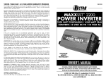
Owners Manual
IT SERIES
Industrial True Sine Wave
AC Power Inverter
IT12-1400
IT12-1600
IT12-1800
Models
IT12-2000
IT12-2600
IT12-2200S IT12-2800
IT12-2400
IT12-3000
IT12-3200
IT12-3600PL
IT24-3500
Owners Manual D98494
IT SERIES Industrial True Sine Wave Inverter
June 18, 2001
Owners Manual
1
IT SERIES Owner's Manual
Typical Installation
OEM
Alternator
OEM Wire
OEM Wire
OEM Wire
OEM
Battery
1/0 Wire Minimum
250 Amp Minimun
1/0 Wire Minimum
Charging Fuse
Charging Fuse
Common OEM
Ground at Starter
or Engine Block
250 Amp Minimum
Inverter Fuse
See Figure 10 for
Fuse and Wire Size
Inverter
Batteries
Inverter
Batteries
Accessory
Polarized Quick
Connectors
AC-2
12 Volt IT Series
DC to AC Inverter
AC-1
Circuit
Breaker
Panel
Box
Field AC Wiring
2
IT SERIES
Industrial True Sine Wave Inverter
Owners Manual
Table of Contents
TABLE OF CONTENTS
1
INTRODUCTION ..............................................................................................................................5
2
SPECIFICATIONS AND FEATURES................................................................................................6
SPECIFICATIONS ..................................................................................................................................6
STANDARD FEATURES ..........................................................................................................................8
PARTS AND ACCESSORIES ....................................................................................................................9
3
SAFETY INSTRUCTIONS ..............................................................................................................10
README.........................................................................................................................................10
GENERAL PRECAUTIONS.....................................................................................................................10
EXPLOSIVE GAS PRECAUTIONS ...........................................................................................................11
BATTERY PRECAUTIONS .....................................................................................................................11
4
COMPONENT IDENTIFICATION AND DESCRIPTION OF OPERATION .......................................12
(4) AUTO THROTTLE INDICATOR LIGHT (VOLT GUARD FEATURE) ........................................................13
(5) LOW BATTERY W ARNING INDICATOR LIGHT (LOW DC W ARNING) ..................................................13
(6) OVERLOAD INDICATOR LIGHT ......................................................................................................13
(7) OVER TEMPERATURE INDICATOR LIGHT........................................................................................13
(8) LOW BATTERY SHUT DOWN INDICATOR LIGHT (LOW DC) .............................................................13
(9) ON/OFF SWITCH (AND RESET SWITCH) ...................................................................................13
(10) INVERTER INDICATOR LIGHT ......................................................................................................14
(13) POSITIVE DC INPUT CONTACT ...................................................................................................14
(14) NEGATIVE DC INPUT CONTACT ..................................................................................................14
(16) CB-2 15 AMP AC OUTPUT CIRCUIT BREAKER ...........................................................................15
(17) CB-1 20 OR 30 AMP AC OUTPUT CIRCUIT BREAKER .................................................................15
(18) CHASSIS GROUND BONDING LUG ...............................................................................................15
(20) AC OUTPUT TERMINAL BLOCK CONTAINING OUTPUTS AC-1 AND AC-2...........................................15
(32) REMOTE CONTROL TERMINAL BLOCK..........................................................................................16
(32.1) Remote ON/OFF Switch Terminals 1, 2 and 3 ..................................................................17
(32.2) Remote Inverter Indicator Light (LED) Terminals 4 and 5 ..................................................17
(32.3) Auto Throttle Control (Volt Guard) Terminal 6 ...................................................................18
(32.5) Remote Low Battery Warning Terminal 8..........................................................................19
(33) GFCI DUPLEX RECEPTACLE .....................................................................................................19
(35) COOLING FAN (NOT SHOWN) ....................................................................................................19
5
INSTALLATION AND START-UP ..................................................................................................20
UNPACKING THE INVERTER .................................................................................................................20
INVERTER INSTALLATION CONSIDERATIONS ..........................................................................................20
DC W IRING CONSIDERATIONS ............................................................................................................20
DC W IRING INSTALLATION PROCEDURE ...............................................................................................21
REMOTE CONTROL W IRING INSTALLATION ............................................................................................23
AC OUTPUT W IRING INSTALLATION PROCEDURE ..................................................................................23
START-UP AND TEST PROCEDURE .......................................................................................................23
IT SERIES Industrial True Sine Wave Inverter
Owners Manual
3
Table of Contents
6
PREVENTIVE MAINTENANCE AND TROUBLE SHOOTING PROCEDURES............................... 24
PREVENTIVE MAINTENANCE................................................................................................................ 24
TROUBLE SHOOTING PROCEDURES ..................................................................................................... 24
7
APPENDIX..................................................................................................................................... 26
W ARRANTY....................................................................................................................................... 26
GFCI TEST RECORD ......................................................................................................................... 27
List of Figures and Tables
FIGURE 1
SPECIFICATIONS FOR MODELS RATED UP THROUGH 2400 WATTS. ............................................... 6
FIGURE 2
SPECIFICATIONS FOR MODELS RATED 2600 WATTS AND HIGHER .................................................. 7
FIGURE 3
INVERTER TOP VIEW ............................................................................................................ 12
FIGURE 4
INVERTER FRONT, RIGHT SIDE AND BOTTOM VIEW .................................................................. 14
FIGURE 5
INVERTER FRONT AND LEFT SIDE VIEW .................................................................................. 15
FIGURE 6
REMOTE CONTROL TERMINAL BLOCK ..................................................................................... 16
FIGURE 7
REMOTE CONTROL SWITCH W IRING VARIATIONS ..................................................................... 17
FIGURE 8
AUTO THROTTLE CONTROL DIAGRAM (VOLT GUARD FEATURE) ............................................. 18
FIGURE 9
REMOTE LOW BATTERY W ARNING ......................................................................................... 19
FIGURE 10 DC CABLE AND FUSE SIZING CHART ...................................................................................... 21
FIGURE 11 UL LISTED RING TERMINALS FOR DC CABLES ........................................................................ 22
FIGURE 12 GFCI TEST RECORD ............................................................................................................ 27
4
IT SERIES
Industrial True Sine Wave Inverter
Owners Manual
Introduction
1 INTRODUCTION
Thank you for purchasing a Vanner IT SERIES Inverter. We are confident that you will be satisfied with its
performance and its many features. With proper installation and care, you can look forward to years of
service from this high performance product.
“IT” stands for Industrial True Sine Wave.
The IT SERIES is a family of dependable inverters designed to meet the severe service requirements of
the industrial market. All models of the IT SERIES produce true sine wave AC output power.
This document will describe the operation, technical specifications and installation procedures of the
various models and accessories offered in this product family. We suggest that you familiarize yourself
with the model numbers of the inverter and optional accessories you have purchased before proceeding
with this manual. If you require additional information please contact your dealer, or contact us directly at
1-800-227-6937 (800 AC POWER).
WARNING:
Before you install and use your IT SERIES Inverter be sure to read and save these
safety instructions.
Model Listing
The IT SERIES product line is designed to meet the requirements of a variety of applications. In order to
meet these requirements we offer 12 volt models in 200 watt increments.
NOTICE:
All models of the IT SERIES use the same front panel and therefore look identical. To
identify the model number of your particular unit it is necessary to refer to the
Specification Label located on the right side of the unit or to the Identification Label
located on the front.
Please note your model and serial number here for future reference.
Model No.________________ Serial No.________________ Date of Installation ______________
IT SERIES Industrial True Sine Wave Inverter
Owners Manual
5
Specifications and Features
2 Specifications and Features
Specifications
Figure 1
Specifications for models rated up through 2400 watts.
Model Number
SPECIFICATIONS
IT12-1400
IT12-1600
IT12-1800
IT12-2000
IT12-2200S
IT12-2400
Rated Output Watts *
1400W
1600W
1800W
2000W
2200W
2400W
Continuous Output
11.7A
1400W
13.3A
1600W
15.0A
1800W
16.7A
2000W
18.3A
2200W
20.0 A
2400W
Surge Output at 3 seconds
22.9A
23.8A
24.7A
25.6A
41.1A
41.6A
AC Power Output
Output Waveform
Total Harmonic Distortion
Output Voltage
Output Frequency
DC Input Voltage Range
DC Input Current
Inverter OFF
True Sine Wave
Less than 4% THD for all loads up to surge output
120 Volts ± 5%
60 Hz ± 0.025 Hz (0.04%)
IT12-XXXX = 10.5 - 16.6 VDC / IT24-3500 = 21.0 TO 33.2 VDC
1 ma
Inverter ON in Load Demand
Mode (No AC load)
Full load at 12VDC
AC Output Wiring Method
One Built-in Receptacle
Two Hardwire Output Circuits
System
Ambient Operating
Temperature
Cooling Air
Enclosure
Dimensions - All Models
Unit Weight
IT12-XXXX =0.5 amps / IT24-3500 = .255 amps
160A
185A
210A
225A
235A
260A
GFCI Duplex Receptacle protected by a 15 amp circuit breaker
Output AC-1: protected by a 20 amp circuit breaker on models up through
2400 watts, 30 amp circuit breaker on models 2600 watts and higher
Output AC-2 protected by the 15 amp GFCI feedthrough on all units
-40 to +105ºF (-40 to +40ºC)
45 Ibs
Thermostatically controlled intake fan
White painted aluminum
8.0"H x 13.75"W x 15.75"D
48 lbs
57 lbs
46 Ibs
47 lbs
70 lbs
*Note: The inverter will try to power any load, even a short circuit, for 3 seconds. When the load exceeds the
inverter's rated output the Overload Indicator Light will turn ON. After 3 seconds, the inverter will reduce the
AC Output Voltage as needed to limit the AC Output Current. If the inverter reduces output voltage below
108 volts for 10 seconds, the inverter will shut itself OFF for Overload.
6
IT SERIES
Industrial True Sine Wave Inverter
Owners Manual
Specifications and Features
Figure 2
Specifications for models rated 2600 watts and higher
Model Number
SPECIFICATIONS
IT12-2600
IT12-2800
IT12-3000
IT12-3200 IT12-3600PL IT24-3500
Rated Output Watts *
2600W
2800W
3000W
3200W
Continuous Output
21.7A
2600W
23.3A
2800W
25.0A
3000W
26.7A
3200W
3600W for
30 minutes
minimum**
30.0A
3600W
Surge Output at 3 seconds
42.1A
42.6A
43.2A
43.7A
43.7A
AC Power Output
Output Waveform
Total Harmonic Distortion
Output Voltage
Output Frequency
DC Input Voltage Range
DC Input Current
Inverter OFF
Two Hardwire Output Circuits
System
Ambient Operating
Temperature
Cooling Air
Enclosure
Dimensions - All Models
Unit Weight
29.2 A
3500W
83.0A
True Sine Wave
Less than 4% THD for all loads up to surge output
120 Volts ± 5%
60 Hz ± 0.025 Hz (0.04%)
IT12-XX.XX = 10.5 - 16.6 VDC / IT24-3500 = 21.0 TO 33.2 VDC
1 ma
Inverter ON in Load Demand
Mode (No AC load)
Full load at 12VDC
AC Output Wiring Method
One Built-in Receptacle
3500W
IT12-XXXX =0.5 amps / IT24-3500 = .255 amps
285A
315A
340A
365A
365A
170A
GFCI Duplex Receptacle protected by a 15 amp circuit breaker
Output AC-1: protected by a 20 amp circuit breaker on models up through
2400 watts, 30 amp circuit breaker on models 2600 watts and higher
Output AC-2 protected by the 15 amp GFCI feedthrough on all units
-40 to +105ºF (-40 to +40ºC)
71 Ibs
Thermostatically controlled intake fan
White painted aluminum
8.0"H x 13.75"W x 15.75"D
75 lbs
75lbs
72 Ibs
73 lbs
75 lbs
*Note: The inverter will try to power any load, even a short circuit, for 3 seconds. When the load exceeds the
inverter's rated output the Overload Indicator Light will turn ON. After 3 seconds, the inverter will reduce
the AC Output Voltage as needed to limit the AC Output Current. If the inverter reduces output voltage
below 108 volts for 10 seconds, the inverter will shut itself OFF for Overload.
** At 77ºF(25ºC) the IT12-3600 can produce 3600 watts for at least 30 minutes before overheating.
IT SERIES Industrial True Sine Wave Inverter
Owners Manual
7
Specifications and Features
Standard Features
1.
True sine wave 120 volt AC output.
2.
Total harmonic distortion less than 4% for all loads up to the Surge Output Rating.
3.
Resilient electronic protection designed to handle output short circuits and output overloads.
4.
Built-in Volt Guard Battery Voltage Monitor, providing ground control for an automatic throttle to
insure maximum alternator output when needed.
5.
Load Demand Feature to conserve DC power under no load conditions.
6.
15 amp GFCI Duplex Receptacle.
7.
Two AC output circuits (one GFCI protected) with individual circuit breakers.
8.
Terminal block for hardwiring the AC outputs.
9.
Automatic shutoff for low or high battery voltage, overload or over temperature.
10.
Remote control circuit capable of single wire input (12 or 24 volt input) or 2 wire (12 volt signal
and return).
11.
Remote indicator light (LED) circuit to operate a remote inverter ON/OFF status LED.
12.
Remote Low Battery Warning Circuit, providing ground control for a remote warning device when
battery voltage falls to 11.0 (22.0) Volts DC.
13.
Terminal block for wiring remote control, remote Inverter ON/OFF LED, remote Low DC Warning
device and Auto Throttle control circuits.
14.
Indicator lights for Auto Throttle Signal, Low Battery Warning, Low Battery Shutoff, Over
Temperature Shutoff, Overload and Inverter ON/OFF/Load Demand status.
15.
All controls and wiring connections accessible from the front of the inverter.
16.
Thermostatically controlled cooling intake fan.
17.
Factory selectable Load Demand ON/OFF. (ON is standard.)
18.
Factory selectable Five Minute Automatic Restart after shutdown due to fault. (OFF is standard.)
Definitions
Load Demand Feature and Load Demand Mode:
The Load Demand Feature is an energy conserving feature which allows the inverter to enter the ‘Load
Demand Mode’ whenever the inverter is ON and the AC load has been less than 10 watts for
approximately 10 seconds. While in the ‘Load Demand Mode’ the inverter does not produce 120 volts AC
but instead produces pulses of voltage which the inverter uses to look for a load. When a load greater
than 10 watts is sensed, the inverter will turn fully ON to produce 120 Volts AC. The ‘Load Demand Mode’
is often also described as ‘stand-by mode’ or ‘sleep mode’. While in the ‘Load Demand Mode’ 12-volt
models consume approximately 0.5 amps of DC and 24-volt models consume approximately 0.25 amps
of DC.
8
IT SERIES
Industrial True Sine Wave Inverter
Owners Manual
Specifications and Features
Parts and Accessories
Part
Number
Name
Description
03644
04521
04523
03646
03637
Bussmann Fuse ANL-250
Bussmann Fuse ANN-300
Bussmann Fuse ANN-400
Bussmann Fuse ANL-500
Bussmann Fuse Holder 4164
250 amp DC fuse for charging cable
300 amp DC input fuse for IT12-1400 thru IT12-2000
400 amp DC input fuse for IT12-2200S
500 amp DC input fuse for IT12-2400 and larger
Fuse holder for the above DC input fuses
D07923-00
Quick Connect DC Input Cable
18” long 4/0 DC Input Cable with 3/8” ring terminals
and polarized 350 amp Quick Connector.
D07923-01
1/0 Quick Connect Cable Set
For use with customer supplied 1/0 DC input cable for
IT12-1400 thru IT12-2000. Includes D07923-00 and
mating quick connector for 1/0 cable.
D07923-02
2/0 Quick Connect Cable Set
For use with customer supplied 2/0 DC input cable for
IT12-1400 thru IT12-2000. Includes D07923-00 and
mating quick connector for 2/0 cable.
D07923-03
3/0 Quick Connect Cable Set
For use with customer supplied 3/0 DC input cable for
IT12-1400 thru IT12-2200S. Includes D07923-00 and
mating quick connector for 3/0 cable.
D07923-04
4/0 Quick Connect Cable Set
For use with customer supplied 4/0 DC input cable for
all IT models. Includes D07923-00 and mating quick
connector for 4/0 cable.
D08403
DC Input Compressing Fitting Kit
Includes 2) D08241 Compression Fittings and
Installation Diagram D98403. Accepts DC input
cables up to 250MCM.
D08506
Remote Switch Assembly
SPST Toggle Switch, 25 foot long cable, 1amp fuse
and fuse holder.
73-46
Automatic Throttle
Vanner Automatic Throttle for mechanical throttle
linkages. (The 73-46 does not apply to electronic
engines having no mechanical linkage to the
accelerator pedal.)
05235
12 volt 30 amp Bosch Relay
Automotive 12 volt SPDT relay with 30 amp contacts.
D08546
20 Amp AC Output Cord Set
NEMA L5-20R receptacle (120 volt, 20 amp, twistlock) on 1’ long 12/3 SO cable with ring terminals and
includes a mating NEMA L5-20P plug.
D07924
30 Amp AC Output Cord
NEMA L5-30R receptacle (120 volt, 30 amp, twistlock) receptacle on 1' long 10/3 SO cable with ring
terminals.
IT SERIES Industrial True Sine Wave Inverter
Owners Manual
9
Safety Precautions
3 SAFETY INSTRUCTIONS
README
WARNING: Before you install and use your IT SERIES AC Power Inverter, be
sure to read and save these safety instructions.
This manual contains important safety and operating instructions for the Vanner Power Group IT SERIES
Power Inverter as prescribed by Underwriters Laboratories (UL). The IT SERIES inverter is listed as
compliant with UL 458, Power Converters/Inverters and Power Converter/Inverter Systems, and UL 1741
Power Conditioning Units for use in Residential Photo-voltaic Power Systems. The IT SERIES is also
listed in the Canadian National Standard CSA – C22.2 No. 107.1957.
NOTICE:
The output waveform of the IT SERIES inverter is sinusoidal. Total harmonic distortion is
less than four percent.
CAUTION:
Read owners manual BEFORE wiring or powering up.
CAUTION:
Not intended for DC input directly from a solar array. Batteries must be used.
CAUTION:
DO NOT cover or obstruct ventilation openings. DO NOT mount in a zero-clearance
compartment. Overheating may result.
WARNING:
Under high ambient temperature / high-power-output conditions some parts of the
inverter may become hot enough to cause burns. The unit should be installed so that it is
not to be contacted by personnel.
WARNING:
This equipment employs components that tend to produce arcs and sparks. To prevent
fire or explosion, DO NOT install in confined areas or compartments that contain batteries
or flammable materials.
WARNING:
Improper use of this product may result in risk of electrical shock. Both AC and DC
voltage sources are terminated inside this equipment.
Use only the ground fault circuit interrupter (GFCI) receptacle(s) or circuit breaker(s)
specified in the installation and operating instructions. Other types may fail to operate
properly when connected to this equipment.
DANGER:
Battery connections are for disconnect only, NOT for current interruption.
General Precautions
1. Do not expose the inverter to direct water spray or snow.
2. To reduce the risk of a fire hazard, do not cover or obstruct the ventilation openings.
3. Do not install the inverter in a zero clearance compartment. This may result in overheating or
diminished performance.
4. To avoid the risk of fire, electrical shock, or injury to persons, do not use attachments not
recommended or sold by the Vanner Power Group.
5. Vanner recommends that all AC and DC electrical wiring be performed by a licensed electrician or a
qualified technician to ensure compliance with all applicable national and local wiring regulations.
6. To avoid a risk of fire and/or electrical shock, always verify wiring connections are in good electrical
condition. All external conductors must use proper wire size to avoid dangerous overheating or
diminished performance.
7. If the inverter has been dropped or damaged in any way, do not operate the inverter until it has been
verified to be safe by a qualified technician.
10
IT SERIES
Industrial True Sine Wave Inverter
Owners Manual
Safety Precautions
8. To reduce the risk of electrical shock, always disconnect the AC and DC connections to the inverter
before attempting any maintenance. Simply turning the inverter off does not prevent electrical shock.
9. The inverter must be properly grounded in accordance with local and national codes and ordinances
before operation. For most installations, the negative (ground) conductor should be bonded to the
grounding system at one and only one point in the system.
10. For optimum inverter performance, battery temperature should be above 32 degrees Fahrenheit.
11. Do not disassemble the inverter. See the service section of this manual for instructions on obtaining
service. Attempting to service the inverter yourself may result in a risk of electrical shock, fire and/or
loss of warranty.
Explosive Gas Precautions
1. This equipment contains components, which tend to produce arcs or sparks. To prevent fire or
explosion, do not install in compartments containing batteries or flammable materials, or in locations
that require ignition protected equipment. This includes any space containing gasoline-powered
machinery, fuel tanks, or joints, fittings, or other connections between components of the fuel system.
2. To reduce the risk of battery explosion, follow these instructions, the battery manufacturer
instructions, and the instructions of the manufacturer of the equipment in which the battery is
installed. Working near a lead-acid battery is dangerous. Batteries generate explosive gases during
normal battery operation.
Battery Precautions
1. Always have someone within range of your voice to come to your aid when you work near a lead-acid
battery.
2. Have close access to plenty of fresh water and soap in case battery acid contacts skin, clothing, or
eyes.
3. Always wear complete eye protection and clothing protection. Avoid touching eyes while working near
batteries.
4. If battery acid contacts skin or clothing, wash immediately with soap and water. If acid enters eye,
immediately flood eye with running cold water for at least 20 minutes. Get medical attention
immediately.
5. NEVER smoke or allow a spark or flame near a battery. Gases produced by batteries are explosive.
6. Be careful when working with metal tools around batteries. Potentials exist for sparks or short-circuit
of the battery or other electrical part which could cause an explosion.
IT SERIES Industrial True Sine Wave Inverter
Owners Manual
11
Component Identification and
Description of Operation
4 COMPONENT IDENTIFICATION and DESCRIPTION of OPERATION
Figure 3
Inverter Top View
(1) Top entry for positive DC input cable
(2) Top entry for negative DC input cable
(3) Top entry for Remote Control Terminal Block
12
IT SERIES
Industrial True Sine Wave Inverter
Owners Manual
Component Identification and
Description of Operation
(4) Auto Throttle Indicator Light (Volt Guard Feature)
(see also item (32.3) Terminal 6 Auto Throttle Control Terminal)
Light Display
Description
Green Light is ON
The Auto Throttle Signal (ground signal) is ON due to battery voltage
remaining below 12.6 (25.2) volts for 15 seconds. The Indicator Light and
the Auto Throttle Signal will remain ON until battery voltage remains above
13.8 (27.0) volts for 15 seconds. The indicator light will also remain ON at
full load output.
The Volt Guard Feature is designed to control an automatic throttle on vehicles where the inverter
is required to operate continuous, heavy AC loads. By controlling the auto throttle the Volt Guard
Feature will insure that the vehicle’s alternator operates at maximum output when needed.
The Volt Guard circuit is designed to provide ‘ground control’ for a Bosch relay, Vanner part number
05235 or equal. Use the Bosch relay to operate the automatic throttle, Vanner 73-46 Automatic
Throttle or equal. See Figure 5 for details and Figure 7 for a schematic diagram.
(5) Low Battery Warning Indicator Light (Low DC Warning)
Light Display
Description
Yellow Light is ON
The inverter is ON and battery voltage has decreased to less than 11 (22)
volts DC. Automatic inverter shutdown for low battery at 10.5 (21) volts is
imminent unless the battery voltage is increased.
(6) Overload Indicator Light
Light Display
Description
Solid Red
The inverter is ON but the inverter’s AC output circuitry is sensing an
overload condition. If the AC load is not reduced, the inverter will shut itself
OFF after approximately 12 seconds.
Blinking Red
The inverter has shut itself OFF due to overload. The Inverter ON/OFF
Switch must be cycled to reset and restart the inverter.
(7) Over Temperature Indicator Light
Light Display
Description
Blinking Red
The inverter has shut itself OFF due to over temperature. The Inverter
ON/OFF Switch must be cycled to reset and restart the inverter.
(8) Low Battery Shut Down Indicator Light (Low DC)
Light Display
Description
Blinking Red
Battery voltage has fallen below 10.5 volts (21 volts) and the inverter has
shut itself OFF. The Inverter ON/OFF Switch must be cycled to reset and
restart the inverter.
(9) ON/OFF Switch (and RESET Switch)
The ON/OFF Switch is a two-position rocker switch used to turn the inverter ON/OFF and is used
as a RESET Switch. When the inverter has automatically shut itself OFF due to a fault, the inverter
must be RESET by turning the ON/OFF Switch OFF or by turning a remote switch OFF. (If an
automatic shutdown has occurred due to a fault, one of the fault indicator lights will be displayed
until the inverter is RESET.
IT SERIES Industrial True Sine Wave Inverter
Owners Manual
13
Component Identification and
Description of Operation
(10) Inverter Indicator Light
Light Display
Description
Green Light is OFF
Inverter is OFF
Solid Green
Inverter is ON and is producing AC power
Blinking Green
Inverter is in Load Demand Mode
Figure 4
Inverter Front, Right Side and Bottom View
(11) Bottom entry for positive DC input cable
(12) Bottom entry for negative DC input cable
(13) Positive DC Input Contact
(14) Negative DC Input Contact
(15) Bottom entry for Remote Control Terminal Block
14
IT SERIES
Industrial True Sine Wave Inverter
Owners Manual
Component Identification and
Description of Operation
(16) CB-2 15 Amp AC Output Circuit Breaker
CIRCUIT BREAKER CB-2 (bottom breaker) protects the GFCI Receptacle and AC Output AC-2.
(17) CB-1 20 or 30 Amp AC Output Circuit Breaker
CIRCUIT BREAKER CB-1 (top breaker) protects AC Output AC-1. CB-1 is a 20 amp breaker on
models up through 2400 watts. CB-1 is a 30 amp breaker on models rated 2600 watts and higher.
(18) Chassis Ground Bonding Lug
(19) Bottom entry for AC output cable
(20) AC Output Terminal Block containing outputs AC-1 and AC-2
(21) Side entry for AC output cable
(22) N/A
(23) N/A
(24) Factory set-up jack
(25) Air Exhaust Vents
Figure 5
Inverter Front and Left Side View
IT SERIES Industrial True Sine Wave Inverter
Owners Manual
15
Component Identification and
Description of Operation
(26) Mounting Brackets ( 2 )
(27) Air Exhaust Vents
(28) Side entry for negative DC input cable
(29) Side entry for positive DC input cable
(30) Positive DC Input Contact
(31) Negative DC Input Contact
(32) Remote Control Terminal Block
A 9-position terminal block is provided for connecting optional, customer supplied remote control
and remote display wiring. Please note that any wiring to this terminal block is optional.
Figure 6
Remote Control Terminal Block
9-POSITION
TERMINAL BLOCK
_____________________________________________
Terminals 1,2 and 3
Remote Switch terminals.
See item (32.1) and Figure 7.
_____________________________________________
Terminals 4 and 5
Remote ‘Inverter ON' LED.
See item (32.2).
____________________________________________
(Volt Guard Feature) Provides
Terminal 6
ground control based on battery
voltage. See item (32.3) & Fig 8.
_____________________________________________
Provides ground control for a
Terminal 8
remote Low Battery Warning
Device. See item (32.5) & Fig 9.
_____________________________________________
Terminal 7 and 9
16
IT SERIES
REMOTE
ON/OFF
1
2
SWITCHES
3
INTERNAL
FUNCTION
POWER-ON
LED
4
+5V
5
GND
6
AUTO
THROTTLE
7
8
LOW DC
WARNING
9
Terminals 7 and 9 are NOT USED.
Industrial True Sine Wave Inverter
No
connection
Owners Manual
No
connection
Component Identification and
Description of Operation
(32.1) Remote ON/OFF Switch Terminals 1, 2 and 3
The IT SERIES Inverter allows four styles of remote control wiring for customers who wish to
supply and install a remote control switch or switches.
Figure 7
Remote Control Switch Wiring Variations
9 POS BLOCK
Standard
Style One
No Remote Switch.
(Factory jumper connecting
terminals 1 and 2.)
Series Remote Switch
powered by Terminal 2.
(Factory jumper removed)
JUMPER
Series Remote Switch
powered externally.
(Factory jumper removed.)
INVERTER ON/OFF
2
+12/24VDC
3
SPST
REMOTE
9 POS BLOCK
INVERTER
INTERNAL WIRING
1
INVERTER ON/OFF
2
1A FUSE
Style Two
INTERNAL WIRING
1
+12/24VDC
3
SPST
REMOTE
9 POS BLOCK
INVERTER
INTERNAL WIRING
1
INVERTER ON/OFF
2
+12/24VDC
+12/24VDC
3
9 POS BLOCK
INVERTER
INTERNAL WIRING
1
Style Three Parallel Remote Switch
powered by Terminal 2.
(Factory jumper connecting
terminals 1 and 2.)
1A FUSE
JUMPER
INVERTER ON/OFF
2
+12/24VDC
3
INVERTER
SPST
REMOTE
9 POS BLOCK
INTERNAL WIRING
1
Style Four
Parallel Remote Switch
powered externally.
(Factory jumper connecting
terminals 1 and 2.)
JUMPER
+12/24VDC
INVERTER ON/OFF
2
+12/24VDC
3
INVERTER
SPST
REMOTE
(32.2) Remote Inverter Indicator Light (LED) Terminals 4 and 5
(See also item (10) Inverter Indicator Light
Use Terminals 4 and 5 to operate a customer supplied remote Inverter LED through a 470-ohm
resistor. The LED will light when the inverter is ON or in Load Demand Mode. A remote Inverter
LED does not blink when the inverter is in Load Demand Mode.
IT SERIES Industrial True Sine Wave Inverter
Owners Manual
17
Component Identification and
Description of Operation
(32.3) Auto Throttle Control (Volt Guard) Terminal 6
(See also item (4) Auto Throttle Indicator Light)
The Auto Throttle Control (Volt Guard Feature) provides a ‘ground signal’ at Terminal 6 and
turns ON the Auto Throttle Indicator Light whenever battery voltage remains below 12.6 (25.2)
volts for more than 15 seconds. The ‘ground signal’ and the indicator light both turn OFF after
battery voltage remains above 13.8 (27.0) volts for 15 seconds. The circuit is designed to
provide ‘ground control’ for a Bosch relay, Vanner part number 05235 or equal.
Use the Volt Guard Feature to control an automatic throttle on vehicles where the inverter is
required to operate continuous heavy AC loads or where other heavy DC loads are present. By
controlling the auto throttle in reference to battery voltage, the Volt Guard Feature insures that
the vehicle alternator produces maximum output when needed.
Use the Bosch relay to control the automatic throttle, Vanner 73-46 Automatic Throttle or equal.
Install a ½ amp in-line fuse near the inverter as shown. The sketch below follows the 73-46
Automatic Throttle wiring instructions as for a Dynamic Inverter installation. This requires
separating the input signal circuit from the input power circuit by cutting the Red 18GA jumper on
the Auto Throttle Control Module. The Bosch relay may also control the Auto Throttle via the
ground similar to the Volt Guard circuit shown in the 73-46 Auto Throttle instructions. For ground
control, route the Auto Throttle’s white/black wire through the Bosch relay’s N.O. contacts.
Figure 8
Auto Throttle Control Diagram
(Volt Guard Feature)
9 POS BLOCK
VANNER 73-46
AUTO-THROTTLE
CONTROL MODULE
INTERNAL WIRING
RED 18
12VDC
HOT IN RUN
VOLT GUARD CIRCUITRY
6
BOSCH RELAY
05235
1/2 AMP
FUSE
1 AMP
FUSE
(32.4) Terminal 7 Not used.
18
IT SERIES
Industrial True Sine Wave Inverter
Owners Manual
Component Identification and
Description of Operation
(32.5) Remote Low Battery Warning Terminal 8
(See also item (5) Low Battery Warning Indicator Light (Low DC Warning)
Terminal 8 is designed to provide ground control for a Bosch relay, Vanner part number 05235
or equal, to operate in conjunction with the Low DC Warning Indicator Light. Use the Bosch relay
to operate an audible alarm, lights or other warning device. The warning will alert personnel that
battery voltage has fallen to 11 (22) volts and automatic inverter shut down for low battery
voltage at 10.5 (21) volts is imminent.
Install a ½ amp in-line fuse near the inverter as shown.
Figure 9
Remote Low Battery Warning
9 POS BLOCK
ALARM
INTERNAL WIRING
LOW DC SHUTDOWN CIRCUITRY
12VDC
HOT IN RUN
8
BOSCH RELAY
05235
1 AMP
FUSE
1/2 AMP
FUSE
(32.6) Terminal 9 Not used.
(33) GFCI Duplex Receptacle
The GFCI is protected by 15 amp Circuit Breaker CB-2 and protects terminal block Output AC-2.
(34) AC Output Wiring Compartment
(35) Cooling Fan (Not shown)
The cooling air intake fan is located on the back of the inverter. Air is drawn in at the back of the
inverter and is exhausted on both sides. Allow a minimum of 1½” clearance (40 mm) at the back of
the inverter and on both sides to insure proper cooling.
IT SERIES Industrial True Sine Wave Inverter
Owners Manual
19
Installation and Start-up
5 INSTALLATION and START-UP
Unpacking the Inverter
1. Inspect the shipping container and equipment for loose or damaged parts. If any damage is found,
immediately notify the freight carrier.
Inverter Installation Considerations
1. Mounting: Locate a secure, dry, flat horizontal or vertical surface large enough to mount the inverter.
The location should be as close to the battery as possible, usually within six feet, but not in the same
compartment and should provide adequate ventilation while the inverter is operating. The location
must be clean, dry and free from road spray, dripping water or other moisture contamination.
2. Cooling Fan Clearance: The mounting location must allow unobstructed airflow for cooling. Allow a
minimum clearance of 1½ inches (40 mm) on the left, right and back sides of the inverter. The
Cooling Fan is a thermostatically controlled intake fan. Air is drawn into the inverter from the backside
and exhausted through vents on the left and right sides. Obstruction of the fan intake or the exhaust
vents will diminish the inverter output capacity due to overheating.
DC Wiring Considerations
1. A DC FUSE IS REQUIRED to properly protect the inverter in case the battery cables are connected
backward (reverse polarity).
2. The wiring of your inverter installation should conform to the National Electric Code (NEC) and any
other state or local codes in effect at the time of installation. These codes have been written for your
protection and their requirements should be followed. Article 551 of the NEC requires any DC cable
from a battery, which measures longer than 18 inches along its length, be protected by a fuse.
3. BE AWARE, as a large number of capacitors become charged upon completion of the DC circuit,
THERE WILL BE A LARGE SPARK when the last battery connection is made. The spark is normal
and will occur every time the batteries are connected. It is advisable to make the last DC connection
at the input fuse, not at the battery, to reduce the risk of battery explosion.
4. Route the AC output wiring and DC power wiring with as much physical separation as possible from
low voltage wiring such as audio and video signal wires.
5. Route the DC positive and negative cables as close together as possible and use cable ties to keep
them together. This reduces electromagnetic radiation that could interfere with sensitive electronics.
6. If passing through steel or other ferrous metal walls, the DC input cables need to pass through the
same hole to prevent causing a transformer effect. If two holes are required, cut a slot to connect the
two holes to prevent heating of the ferrous metal.
20
IT SERIES
Industrial True Sine Wave Inverter
Owners Manual
Installation and Start-up
7. Proper DC cable size is critical for the performance and safe operation of the inverter system. The
DC Cable and Fuse Sizing Chart shows the minimum recommended cable sizes. These sizes allow
a ½ volt maximum voltage drop at maximum inverter capacity and will insure optimum inverter
performance. Quick DC cable connectors are available. See Parts and Accessories.
8. Do not use the vehicle chassis as the DC negative conductor. The negative cable should be the same
size as the DC positive cable and should be connected directly to the battery negative terminal.
9. DC cables should be as short as possible.
Fuse (Bussmann)
Vanner part number
IT24-3500
IT12-3200
IT12-3000
IT12-2800
IT12-2600
IT12-2400
IT12-2200S
IT12-2000
IT12-3600PL
Cable Size
1/0
2/0
3/0
4/0
250MCM
IT12-1800
Model Number
IT12-1600
DC Cable and Fuse Sizing Chart
IT12-1400
Figure 10
NR
NR
NR
10*
12*
NR
NR
NR
11
13
Distance from battery to inverter in feet
(Length of cable needed is 2 times the distance.)
12
16
20
20
20
11
13
16
20
20
10
12
15
19
20
ANN300
04521
Fuse Holder
9
11
14
18
20
NR
NR
14
17
20
NR
NR
NR
15
17
ANN400
04523
NR
NR
NR
14
16
NR
NR
NR
13
16
NR
NR
NR
12
14
NR
NR
NR
11*
13*
ANL500
03646
Vanner part number 03637 (Bussmann 4164)
*For 12 volt models rated-2800 watts and higher use cable rated 90°C, UL listed 4/0 cable 03558, or equal.
Note: A 500 amp fuse is required to achieve full surge output capacity on Model IT24-3500. Usage of the
500 amp fuse dictates using 4/0 cable or larger.
DC Wiring Installation Procedure
1. The DC wiring enclosure is located on the left front of the inverter. The DC cables may enter the
inverter through top, bottom or left side openings (see figures 1,2,and 3). Two cable clamps and four
plastic hole plugs are provided. Bolts are provided for connecting 5/16 diameter ring terminals to the
DC Input Contacts. Optional compression lugs (Vanner part no. D08241) are available for cables
sizes up to 250 MCM.
2. Select a location for the inverter. An ideal location is close to the battery; protected from weather and
moisture; and well ventilated.
3. Select an accessible location for the DC Fuse. The location should be within 18” of the battery and
accessible for visual inspection and replacement. If possible locate so the last DC connection can
safely be made at the fuse.
IT SERIES Industrial True Sine Wave Inverter
Owners Manual
21
Installation and Start-up
4. Remove the cover plate on the DC cable compartment to expose the positive and negative DC
contacts and the Remote Control Terminal Block.
5. Prepare DC cable ends. Use ring terminals or, if using the optional D08241 Compression Lugs, leave
the cable ends bare.
Figure 11
UL Listed Ring Terminals for DC Cables
Wire
Gauge
Molex Part No.
Ring
Size
Molex
Description
1/0
H-381-56
H-791-56
H-981-56
5/16
2/0
J-385-56
J-785-56
J-985-56
3/0
K-390-56
N/A
K-990-56
Recommended Crimp Tools
Molex Brand
AC Terminals Inc
Brand
Versacrimp*
Nylacrimp
Funnel Nylacrimp
DLHH, PPDLH, SKT-840
DLHH, PPDLH
DLHH, PPDLH
Crimp Master
0280
5/16
Versacrimp*
Nylacrimp
Funnel Nylacrimp
DLHH, PPDLH, SKT-840
DLHH, PPDLH
DLHH, PPDLH
Crimp Master
0280
5/16
Versacrimp*
Nylacrimp
Funnel Nylacrimp
DLHH, PPDLH, SKT-840
DLHH, PPDLH
DLHH, PPDLH
Crimp Master
0280
L-395-38
Versacrimp*
DLHH, PPDLH, SKT-840
Crimp Master
4/0
N/A
3/8
Nylacrimp
DLHH, PPDLH
0280
L-995-38
Funnel Nylacrimp DLHH, PPDLH
*Require shrink wrap insulation applied to barrel: 1/0 to 2/0 use Molex PFV-¾, 3/0 to 4/0 use PFV-1.
Molex telephone number 813-521-2700.
AC Terminal telephone number 614-868-9828.
6. Verify that the battery positive cable is not connected to the battery. Insert DC cables through the
strain reliefs and into the DC wiring compartment. Torque DC cable mounting bolts to 180 inch
pounds. Re-torque after 30 days. (If using the optional D08421 Compression Lugs, torque the Allen
mounting screw to 180 inch pounds and the Allen compression screw to 240 inch pounds. Re-torque
after 30 days.) Tighten the two strain relief cable clamps. Insert the four plastic plugs into the unused
cable openings.
7. Inspect the DC cable compartment to be sure no copper wire fragments are present after tightening
cables.
8. Route the negative DC cable to the battery. Verify cable polarity before proceeding. The fuse will be
blown and inverter can be damaged if the DC cables are reversed. Route the positive DC input cable
to the fuse and then to the battery. Protect cables with loom and use grommets or other appropriate
means where cables may contact hard, sharp edges. If possible, make the last DC connection at the
fuse to avoid causing a spark at the battery.
9. Connect Chassis Ground Bonding Lug to the vehicle chassis and/or earth ground using AWG No.8 or
larger copper conductor.
10. Verify that the inverter will turn ON but do not leave the inverter connected to the battery at this time
(remove the fuse). Final battery connections will be made after all control and AC output installation
issues have been inspected.
22
IT SERIES
Industrial True Sine Wave Inverter
Owners Manual
Installation and Start-up
Remote Control Wiring Installation
1. Refer to the wiring sketches found in the Component Identification and Description of Operation
section, item (32), Remote Control Terminal Block. Use fuses where indicated.
2. Use cable clamp provided to secure wiring. A plastic plug is provided for the unused opening.
AC Output Wiring Installation Procedure
WARNING: Before proceeding with the AC wiring, verify that the inverter is OFF and that the
inverter is NOT connected to the battery. Serious or fatal electrical shock may occur.
1. The wiring of your inverter installation should conform to the National Electric Code (NEC) and any
other state or local codes in effect at the time of installation. These codes have been written for your
protection and their requirements should be followed
2. Route the AC output wiring, and DC power wiring, with as much physical separation as possible from
low voltage wiring such as audio and video signal wires.
3. Remove the right front cover to expose the AC wiring compartment and the AC Output Wiring
Terminal Block. Output Circuits AC-1 and AC-2 are identified on the terminal block label and are
defined in Section 2, items 16, 17 and 20.
4. A cable clamp is provided to secure the AC output wiring. A plastic plug is provided to plug the
unused opening.
5. Verify AC wiring installation. Verify that all connections are tight. Secure all wiring.
Start-up and Test Procedure
After the inverter has been properly mounted with sufficient ventilation, DC cables have been connected
to the inverter (but not yet to the battery), AC wiring has been completed, and all remote connections
have been checked; the Start-up and Testing procedure should be performed.
WARNING: These procedures are to be performed only by a QUALIFIED INSTALLER.
Inverter Start-up and Testing
1. Place the Inverter ON/OFF switch in the OFF position.
2. Place any remote switches in the OFF position.
3. Verify that any external AC output circuit breakers and GFCI receptacles are reset.
4. Connect the battery to the inverter. BE AWARE, as a quantity of capacitors become charged upon
completing the DC circuit, THERE WILL BE A LARGE SPARK when the last connection is made.
5. Turn the inverter ON and use a test load (75 watt trouble light) plugged into the 15 amp GFCI
receptacle to verify the inverter produces AC power.
6. Refer to the description of operation of the indicator lights, Section 2, items 4 through10 to follow and
verify correct inverter operation.
7. If the inverter is not operating as described, see Trouble Shooting Procedures
IT SERIES Industrial True Sine Wave Inverter
Owners Manual
23
Preventive Maintenance and
Trouble Shooting Procedure
6 Preventive Maintenance and Trouble Shooting Procedures
There are no user serviceable components inside the inverter. If the inverter requires service, refer
to the Vanner Power Group or other qualified service personnel.
Preventive Maintenance
For continued reliability and safety, a monthly maintenance program should be implemented to include
the following:
1. Check to insure that all wiring connections are tight, secure and corrosion free.
2. Check fan intake and exhaust vents for obstructions.
3. Examine receptacle, indicators and switches for cracks and breaks.
4. Examine any surfaces that are discolored or deformed due to excessive heat.
Trouble Shooting Procedures
The following are the most common questions heard by Vanner service professionals. If your situation
does not apply to the following categories, please contact your local Vanner Power Group Service Center
or the Vanner Power Group Customer Service Department: 1-800-AC-POWER (1-800-227-6937). Please
have your model and serial number available when consulting customer service.
Preliminary Checks
1. Indicator Light status
2. Inverter ON/OFF Switch and Remote ON/OFF Switch positions
3. AC Output Breakers CB-1, CB-2
4. Check all GFCI receptacles and circuit breakers as equipped throughout AC system
5. Battery voltage at battery and battery voltage at the inverter. Voltage present at inverter does not
prove that all connections are sound especially under no AC load. (see item 7)
6. DC Fuse condition
7. Battery connections for tightness or corrosion
8.
Try operating an AC load from the GFCI receptacle located on inverter front panel
Problem Symptoms and Troubleshooting Checks
Problem:
Check:
Inverter Indicator Light does not turn ON.
Verify DC voltage at the inverter.
Problem:
Check:
Inverter Indicator Light is ON but the AC load will not operate.
Check and reset GFCI receptacle or circuit breakers. Verify AC wiring. Try a different load
such as a trouble light.
Problem:
Check:
Low Battery Indicator Light is ON when AC load is applied.
Check battery connections and condition. Recharge battery if voltage is less than 10.5 (21.0)
VDC.
Problem:
Check:
Over Temperature Indicator Light is ON.
Verify fan operation. Remove obstructions from air exhaust vents and cooling fan.
24
IT SERIES
Industrial True Sine Wave Inverter
Owners Manual
Preventive Maintenance and
Trouble Shooting Procedure
Problem:
Check:
Overload Indicator Light is ON when AC load is applied.
Verify AC load is within the inverter’s rated capacity. Remove excessive loads.
Problem:
Check:
DC fuse blows when connecting DC input cables.
Check for reverse polarity (Positive and negative DC cables reversed.)
Problem:
Check:
Excessive audible buzzing during inverter operation but inverter operates loads.
Check mounting bracket bolt tightness.
Problem:
Check:
AC loads do not seem to be fully energized when operating from inverter power.
Check AC output voltage at convenience receptacle. Check for overheated DC or AC wiring.
Verify AC load specifications are not exceeded.
Problem:
Check:
Unit does not operate and a “burnt wire” smell emits from inverter.
Disconnect AC loads and battery immediately. Unit may require service, contact Vanner
service department.
IT SERIES Industrial True Sine Wave Inverter
Owners Manual
25
Appendix
7 APPENDIX
Warranty
NORTH AMERICAN LIMITED WARRANTY
Vanner Inc., doing business as The Vanner Power Group, referred to herein as Vanner, warrants that this
product is free from defects in materials and workmanship for a period of two (2) years from date of
installation or two and one half (2 1/2) years from date of manufacture, whichever is less if and only if the
following requirements are complied with:
1. The product is installed and checked out properly according to all guidelines, instructions, and
checkout procedures set forth in the product Installation and Operating Manual.
2. The installer records all checkout data required and completes, signs, and returns the warranty
registration card to Vanner within ten (10) days after installation.
3. The product was purchased after January 1, 2000.
Vanner does not warrant its products against any and all defects when: defect is a result of material or
workmanship not provided by Vanner; normal wear and tear, or defects caused by misuse or use in
contrary to instructions supplied, neglect, accident, reversed polarity, unauthorized repairs and/or
replacements.
All warranties of merchantability and fitness for a particular purpose: written or oral, expressed or implied,
shall extend only for a period of two (2) years from date of installation or two and one half (2 1/2) years
from date of manufacture, whichever is first. There are no other warranties that extend beyond those
described on the face of this warranty. Some states do not allow limitation on how long an implied
warranty lasts, so the above limitations may not apply to you.
Vanner does not undertake responsibility to any purchaser of its product for any undertaking,
representation, or warranty made by any dealers or distributors selling its products beyond those herein
expressed unless expressed in writing by an officer of Vanner.
Vanner does not assume responsibility for incidental or consequential damages, including, but not limited
to, responsibility for loss of use of this product, removal or replacement labor, loss of time, inconvenience,
expense for telephone calls, shipping expense, loss or damage to property, or loss of revenue. Some
states do not allow the exclusion or limitation of incidental or consequential damages, so these limitations
may not apply to you.
Vanner reserves the right to repair, replace, or allow credit for any material returned under this warranty.
Any damage caused by the customer will be charged or deducted from the allowance.
All warranty work will be performed at Vanner’s factory, or authorized repair facility utilizing a valid
Warranty Authorization Number (WAN) prior to repair. Products shall be delivered to Vanner’s facility,
freight prepaid and fully insured. Products repaired under warranty, or replacement parts or products will
be returned to North American location prepaid via same transportation means and level of service as
received, unless directed otherwise. Prepaid freight policy does not apply to locations outside North
America.
26
IT SERIES
Industrial True Sine Wave Inverter
Owners Manual
Appendix
GFCI Test Record
For maximum protection against electrical shock hazard, operate the Test Switch on the Ground Fault
Circuit Interrupter at least once a month and record the values in this supplied table.
Figure 12
YEAR
GFCI Test Record
JAN
FEB
MAR
APR
MAY
JUN
JUL
AUG
SEP
OCT
NOV
DEC
20___
IT SERIES Industrial True Sine Wave Inverter
Owners Manual
27
IT Series Owner's Manual
Vanner Power Group
4282 Reynolds Drive
Hilliard, Ohio 43026
1-800-AC POWER
(1-800-227-6937)
Tel: 614-771-2718
Fax: 614-771-4904
www.vanner.com
e-mail: [email protected]
Manual Part Number D98494
Printed in USA
28
IT SERIES
Industrial True Sine Wave Inverter
Owners Manual