1
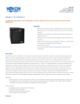
-1-
SAFETY INSTRUCTIONS
CONTENT
SAFETY INSTRUCTIONS
INTRODUCTION
FRONT AND REAR PANEL
INSTALLATION
OPERATION
UPS STATUS DISPLAY
TROUBLE SHOOTING
SERVICE
BATTERY REPLACEMENT
INPUT FUSE REPLACEMENT
STORAGE AND PRESERVATION
SOFTWARE INSTALLATION
1
4
10
16
19
21
27
30
31
33
34
34
Please read carefully and follow this ULTRA Series UPS guide.
Important : Please keep this user's guide for reference in order to use the UPS properly
and safety. This user's guide contains instructions for installation, operation
and specifications.
For product safety, please check this product annually by our service qualified personnel or if there are any symptoms of problems which are not mentioned in this guide or
an queries, please contact your LEONICS local distributors,LEONICS Service Center, send
e-mail to [email protected] or visit www.leonics.com.
For your convenience and quick reference for our service, please
fill the requested information in the blanks below.
UPS Model
: __________________________________
Serial Number : __________________________________
Purchased date : __________________________________
Purchased from : __________________________________
Caution
Risk of electric shock, DO NOT remove cover. No user serviceable part
inside, please refer servicing to qualified service personnel.
1.1 Electrical Safety
1.1.1
1.1.2
1.1.3
1.1.4
Do not work alone where there are electrically hazardous conditions.
Contact with live conductors will cause burns and dangerous electric shock.
Only qualified electricians allow to install and wiring this unit and the system.
Periodically check your cable, terminal and power source to make sure that
they are in good condition.
1.1.5 To reduce risk from electric shock if you can not find the electrical ground
(
) of the building, unplug the UPS from the AC source before plug in your
load at the rear side of the UPS. Then, plug in the UPS to AC source.
-2-
1.1.6 Do not touch any metal parts or any electrical connection when UPS is operating.
1.1.7 Use ONLY one hand when plugging and unpluging the load in order to avoid
electric shock from touching two surfaces with different potential.
1.1.8 It is recommended to connect the UPS to a three wire AC source (two live wires
and ground) which connects to a protected circuit such as employs a fuse or
circuit breaker.
-3-
1.3 Warning ! Battery Safety
1.3.1 Although the UPS is not connected to any power source, its outlets may be
energized because it has a battery inside.
1.3.2 The UPS has hazardous voltages inside, do not disassemble any parts of UPS
except for the battery. Users are not allowed to repair, recondition or
disassemble the UPS. This must be done by Leonics qualified technicians only.
1.2 CAUTION ! Safety guide for installation and operation
1.2.1 Before installing or using this unit, read all instructions, caution markings on
the UPS and all connected load, and all sections of this user guide.
1.2.2 Install this unit in a temperature and humidity controlled indoor area with
adequate air flow and away from chemical particles or flammable substances .
Avoid installing the unit near radio transmission station, heat dissipation equipment and direct sunlight.
1.2.3 This unit has ventilation grills. Ensure that sufficient ventilation is provided.
DO NOT block the ventilation grills.
1.2.4 Use insulated tools to reduce your risk of electric shock.
1.2.5 Remove all jewelry or other metal objects such as rings, necklace, bracelets
and watches when installing this product.
1.2.6 Properly wiring the cables as shown in the wiring diagram.
1.2.7 Before connecting the communication interface signal cable, Turn off the UPS
by pressing the front panel button until the Utility Line OK/Fail (
) and
Overload Alarm (
) lamps are lit at the same time and the alarm sounds
once. Then, release the button.
1.2.8 Turn on the UPS before turn on the load to prevent surge from the loads.
1.2.9 DO NOT connect utility power to the UPS OUTPUT. This may cause the UPS
damaged.
1.2.10When heavy rain, avoid using electronic equipments including UPS to prevent
it from lightning.
1.2.11Use soft cloth to clean the UPS when it is turned OFF. DO NOT clean it with
solvent.
1.2.12DO NOT use the UPS with life recovery instruments. The failure of UPS may
cause life recovery instruments failure or effect to their performance or effect
to the safety system of those instruments.
This product contains sealed lead acid battery and must be recycled
properly. For recycling please return it to a LEONICS local distributor or
LEONICS Service Center or contact your local recycling center for proper
disposal information.
1.3.3 Do not dispose of batteries in a fire. They may be exploded.
1.3.4 Do not disassemble batteries. They contains poisonous electrolyte which is
harmful to your skin and eyes.
1.3.5 Replace batteries with the same type and rating and follow the proper battery
replacement procedure.
1.3.6 When replacing a battery, use tools with insulated handles and remove any
watch, rings or other metal objects that you wear in order to avoid electric
shock.
1.3.7 If user has to keep the UPS or does not use if for long time, recharge the battery
every 3 months in order to preserve the battery. To recharge the battery,
connect it to the AC utility and turn on the UPS for 8 hours.
Load
:
UPS
VA
Option
:
:
:
Vocabulary
Any electrical equipment which is connected to the UPS and gets power
from the UPS such as a computer, printer, fax machine or modem.
ULTRA Series UPS
The unit of UPS power rating showing its capacity.
The additional function or device that is not supply with standard
product.
-4 -
-5-
INTRODUCTION
The ULTRA Series UPS can be started when there is no power source. It is convenient for you to have spare power when the source fails or in an emergency. It
also can communicate with a computer through the Easy-Mon X Monitoring and
Management Software (sold separately) via USB or RS-232 (for some model) port .
This software can monitor the UPS and AC source status on PC that connected
directly to UPS. It allow user to schedule on-off the UPS, schedule self-test and data
log. It also can monitor the UPS and AC source status of the UPS in the network through
Easy-Mon Netview Manager (sold seperately) and alarm the blackout status on
computer server to client computer in the network through Easy-Mon Alert (sold
seperately).
2.2.1 Operating in the normal mode
The ULTRA Series UPS is a compact, light weight and attractively designed
uninterruptible power supply for office automation equipment (computers and
peripherals such as monitors, modem, printers, fax machines, etc.). Its major function
is to eliminate any power problem such as a black out, brown out, sag, surge, spike,
noise, etc. that might cause malfuction of the load causing work interruption. With its
Advanced Microprocessor Control, when the UPS detects any abnormal conditions, it
will respond instantaneously. It also has special features: Power Watcher, a full time
load measuring system, Battery Watcher, the battery capacity checking system, Ultra
Fast Charger, providing less than 3 hours charging time without shortening battery
life and Perfect Ultra Display, which shows the current status of the UPS ( load level,
input voltage level, battery level, battery replacement condition and overload
condition) and Advanced Load Outlet Management (ALOM), which the user can
program to turn off a low priority outlet when there is a low battery or overload
condition (for 1050VA or higher only). For the UPS with LED display and EASY display,
LED lamps represent the messages or status. For the UPS with LCD display, the
messages or symbols show on LCD screen.
2.2 ULTRA Series UPS Operation
2.1 General
-7-
2.2.2 Operating under backup mode
-6-
2.2.1 Operating in the normal mode
Normally, UPS is working under line interactive mode in which the path of
current is as follows : When the current first flows into the UPS, it has to pass
through a surge protection circuit to filter surges and spikes which may occur
from a nearby lightning discharge or load switching by the local power
company. Here, the high voltage power will go to the line grounding system
and let only the acceptable current pass to the EMI/RFI filter to eliminate EMI
and RFI. Then it flows to the automatic voltage regulator (AVR) to regulate the
voltage level to approximately your country's standard nominal mains voltage
(see product specification, 100, 110, 120, 220, 230 or 240 Volts). If the voltage is
too high or too low compared to the standard nominal voltage, it will be
adjusted to the safety level for your loads (please refer to the specifications).
After that the current will flow to two destinations. The first part goes to the
EMI/RFI attenuation then to the Power Watcher and to your connected loads.
The Power Watcher provides information about load conditions, whether or
not you are overloading your ULTRA Series UPS. (Power Watcher is continuously
monitoring in real time both for the stabilizer and inverter modes.) The
remaining power flows to the battery charger circuit to charge the batteries
and maintain them fully charged.
2.2.2 Operating under backup mode
The UPS will transfer to backup mode (inverter mode) when it detects
abnormal situations such as blackouts, brownouts, surges, sags or abnormal
frequency. These situations may harm your loads and may be too risky for the
UPS to operate in the interactive mode. When an abnormal power mode is
detected, the UPS will Immediately transfer to the backup mode with no loss of
power to the loads. At this moment, the backup power will begin to be drawn
from battery. The current from the battery will flow to the inverter (changing
direct current to alternating current). Then, the power flows to the EMI/RFI
attenuation, Power Watcher and on to your loads.
You can also monitor the UPS from a PC by using Easy-Mon X Monitoring and
Management Software through a connection between the PC and the UPS
communication port. For instance, you can set the UPS shutdown time and restart time,
this status will be displayed on your PC monitor.
-8-
2.3 Features
Advanced LEONICS Microprocessor control: A specially programmed
microprocessor produced only for LEONICS is used as the CPU for the UPS.
This makes the ULTRA Series UPS perform faster and more accurately to
protect valuable equipment and its peripherals and provides advanced
control features.
Power Watcher: Full time load power monitoring and battery charge
warnings are provided to make sure that your UPS will be able to properly
backup power to the PC protected by UPS. "Power Watcher" helps users
know in real time that they are not overloading their UPS. With this useful
feature you can increase loads as much as you want until the UPS overload
warning is shown. (LEONICS suggests that for highest reliability and safety
that you should connect loads at no more than 75 % of rated UPS power.
This allows for loads that change power level during use and provides for
some reserve backup power for some loads.)
Battery Watcher (Battery Replacement Indicator): Every time ULTRA
Series UPS performs a self-test and when the battery has been fully
charged, it will perform a battery condition evaluation to determine
whether the battery used by the ULTRA Series UPS is still good or should
be replaced. The battery replacement indicator will show when the
battery should be replaced.
Ultra Fast Charger: This UPS features an advanced, 3 stage charger (Bulk Boost - Float) to shorten charging time without harming the battery.
Besides fast charging, UPS also maintains the proper charging voltage to
preserve the battery from self-discharge and to make sure that it is always
fully charged and ready to provide backup power to your PC.
Intelligent Battery Management (IBM): The intelligent battery
management system will manage charging and discharging to get
longer backup times and prolong battery life.
Advanced Load Outlet Management (ALOM): This feature allows the
user to preset operation of the "Intelligent Channel" via Easy-Mon X
Software. The user can preset the intelligent output channel to cut off
power to low priority loads when the UPS is overloaded, over temperature
or has a low battery (available on 1050 VA or higher model only).
-9-
Hot Swappable Battery: The user can replace the battery even when the
UPS is running and without turning off the computer as long as mains
power is available.
Surge Protection for Telephone Line: Surge protection protects
equipment data from surges that come from telephone line (RJ11).
Surge Protection for LAN Line (option): Surge protection protects
equipment data from surges that come from LAN line. These special
sockets can accept either telephone plugs (RJ11) or LAN plugs (RJ45).
Perfect LED Display (depend on model): Attractive outlook with full
function LED display. It shows load level, input voltage level, battery level,
battery replacement condition and overload condition.
Perfect LCD Display (depend on model): Attractive outlook with full
function LCD display. It shows load level, input voltage level, battery level,
battery replacement condition and overload condition.
Easy Display (depend on model): Simple outlook with easy function
display. It shows utility line status, battery status and load status.
Multi-function switch : Single switch with 4 functions, very convenient to users :
1. Turn on / Turn off UPS
2. Mute audible alarm
3. Self-test switch
4. Switch display mode (For the UPS with LED display only.)
Extend Backup Time (option): It extends the battery unit to increase the
duration of UPS backup time. It can protect data with extra effectiveness.
Inverter temperature sensor (option): When the UPS is operating under backup
mode, the inverter temperature sensor will check the temperature inside inverter and
warning when the temperature is too high. You should reduce the load immediately.
Automatic voltage regulator -37% to +30%. buck and double boost (option) :
With it’s especially wide range automatic input voltage regulator, from –37% to +30%,
UPS can lessen backup mode transferred transaction, which helps you save the
battery‘s energy for emergencies, it also prolongs your battery life. (This optional is
special for specific models, please see your features on the side of the carton).
- 10 -
- 11 -
FRONT AND REAR PANEL
3.1 Front panel
EASY DISPLAY
LED DISPLAY
LCD DISPLAY
3.1.1 Multi-function Switch: The switch to turn on, turn off, test the UPS and mute
the audible alarm. For LED Display UPS, you can press it to change the display
mode from input voltage - load level mode to battery voltage level mode and
vice versa.
3.1.2 Utility Line OK / Fail (Lamp no. 1: green): Shows the utility power status.
Lit
: UPS is operating under its normal mode.
Blink : UPS is operating in the backup mode.
Note: 1. For the UPS with inverter temperature sensor (option) ; It will be blink
fastly when the temperature in inverter is very high.
2. For 1050 VA or higher model, if the Intelligent channel is turned off,
it will blink slowly (on 1.3 seconds, off 0.2 second).
3. In backup mode, the lamp no.1 and no.8 will be blink twice every
1.5 second.
3.1.3 Low Battery / Replace Battery (Lamp no. 2: yellow)
Lit
: Battery need to be replaced.
Blink : Battery low, UPS is about to run out of power (in case of working in
- 12 -
3.1.4
3.1.5
3.1.6
3.1.7
3.1.8
backup mode).
Overload Alarm (Lamp no. 3: red): Shows load status. It will be lit when your
connecting loads are exceeding the UPS capacity.
Load Level: Shows how much power your loads are consuming compared
to the UPS capacity from low to high level.
3.1.5.1 For the UPS with LED display (Lamp no. 4-7:green): Each lamp
represents 25% of full load capacity and starts from Lamp no. 4 to 7.
Please refer to section 6.2 The meaning of LED display.
3.1.5.2 For the UPS with LCD display: Each bar represents 25% of full load
capacity and starts from the thin bar to the thick bar. Please refer to
section 6.3 The meaning of LCD display.
Input Voltage: Shows the normal mode or stabilizer mode status.
3.1.6.1 For the UPS with LED display (Lamp no. 8-11: green): One of 4 lamps
lights or blinks only at a time. Please refer to section 6.2 The meaning
of LED display.
3.1.6.2 For the UPS with LCD display: One of 4 symbols lights or blinks only at
a time. Please refer to section 6.3 The meaning of LCD display.
Battery Level: Shows the battery voltage from low to high level.
3.1.7.1 For the UPS with LED display (Lamp no. 4-11: green): Shows battery
voltage presents by lamp no. 4 to 11 from low to high level. In normal
mode, these lamps show load level and input voltage. The display
changes to battery level display only when switch display mode or
the UPS is supplying backup power from battery. To switch to battery
level display, please refer to section 5.5 Switch display from input
voltage - load level to battery voltage level or vice versa.
(Please refer to section 6.2 The meaning of LED display.)
3.1.7.2 For the UPS with LCD display: Each bar represents backup power in
the battery which from the thin bar to the thick bar. Thin bar stands
for low battery and 5 following bars represent 20% of full power each.
(Please refer to section 6.3 The meaning of LCD display.)
Replace battery: Indicates replace battery status (for UPS with LCD display).
Replace the battery when this messages and Low Battery/Replace Battery lamp
lights.
- 13 -
3.2 Rear panel description
- 14 -
3.2.1 Surge protection for telephone line / LAN line (option): A port for fax / modem
line surge protection. Its function is to protect load against voltage spikes
coming from the telephone or LAN line (option).
3.2.2 No Load Shutdown Switch: Allows you to select whether the UPS will shutdown
itself when power line fail if there is no load or not (no load are defined as all
loads that connected to the UPS are less than 8 percent of UPS capacity).
3.2.3 USB Port or RS-232 port (option): The communication port for connecting the
UPS to PC. The signal from the UPS will send information to the PC through this
port via USB cable or RS-232 cable (option) and display data on Easy-Mon X
Monitoring Software.
3.2.4 Full time surge protection output for laser printer: The outlet that connects
surge protection circuit. This socket is for Laser Printer or other high power
consumption devices such as scanner. There is no backup power from this
outlet.
3.2.5 UPS output : Loads supplied from these outlets are full time monitored under
Power Watcher. They are provided for the loads that the user wants to protect
and provide a back up power supply when there is a power failure. Loads may
be added until Power Watcher warns of an overload. (LEONICS suggest to
connect load at no more than 75 % of UPS rated power for safety and enough
backup power for those loads that need irregular power.) For 1050 VA or higher
model, the UPS output has two channels as follows.
3.2.5.1 Main Channel: The main outets that is always connected to the UPS
backup system. It is provided for high priority electrical equipments
such as a computer or server.
3.2.5.2 Intelligent Channel: A supplemental outlets that the user can manage
and control by Easy-Mon X Software (See item 12.2). The Intelligent
Channel can be set to permanently turn on or can be set to perform in
intelligent mode to :
1. Turn on with a delay of 0 - 4,000 seconds after the Main Channel
turn on.
2. On commercial power :
2.1 Turn off when there is UPS overload.
2.2 Automatic re-supply after an overload has been removed.
- 15 -
3. On Battery Operation :
3.1 Turn off when UPS gets over temperature.
3.2 Turn off when battery is low.
3.3 Turn off when there Is UPS overload.
Note: 1. Intelligent Channel is set to permanently 'ON' from the factory.
2. If set the Intelligent Channel to On battery operation mode and
disabled, the UPS will re-supply automatically when the utility
power returns to normal.
3. Loads which are connected to the Intelligent Channel should
be low prioirty such as a printer or scanner.
3.2.6 AC input: The power socket for plug in the input power cord. In Ultra Series
UPS 650 VA or smaller, it is the power socket with buit-in fuse holder and spare
fuse holder socket.
3.2.7 Fault wiring: A indicator light shows the fault wiring of the utiliy line which
connects to the UPS. The fault wiring can be either the wiring of line or neutral
are crossed or no electric ground. If this indicator light is extinguished, it means
the wiring is correct.
3.2.8 Battery extension port (option): The port for connecting with an extension
battery unit to increase the duration of UPS backup time.
3.2.9 Dip switch: The switch for setting the no load shutdown system. The switch
no.1 use for enable/disable no load shutdown system.
Note: SW 2 - SW 4 are not available at the present.
3.2.10 Magnetic breaker: A circuit breaker that protects the UPS from overload or
short circuit current (available on 1050 VA or higher model).
- 16 -
INSTALLATION
- 17 -
4.4.2 IEC type outlets
Plug UPS output power cord which is supplied with the UPS into the
UPS outlet and the inlet of the load.
4.1 Connect a signal cable from PC network (if available) to the
USB port (or RS-232 port (option)) of the UPS.
4.2 Connect telephone line or LAN line (option).
IN
: Connect telephone or LAN line (option) to UPS.
OUT : Connect telephone or LAN line (option) from UPS to
the input socket of fax machine, modem or LAN card.
Note: To gain proper benefit from telephone or LAN line surge protection, your
electricity system should have an electric ground. If there is no electric ground
wire, there can be data transferring problems and loss of protection of the
connecting devices.
4.3 No load shutdown switch enable / disable
ULTRA Series UPS 650VA or smaller
ULTRA Series UPS 1050VA or higher
Set the dip switch SW1 to "ON" as shown if you want the UPS to shutdown
automatically in backup mode when the load is less than 8 % of full rated power in
order to save energy and prolong battery life.
Note: No load shutdown is set at "OFF" from the factory.
4.4 Plug the UPS loads such as computers, printers, modem and etc to the UPS outlets.
4.4.1 Standard outlets
Plug the load power cord into the UPS outlets as shown in the figure below.
4.5 Plug the UPS to utility line
4.5.1 Standard outlets
Plug UPS input power cord into UPS's AC Input and wall receptacle as shown
in the figure below.
- 18 -
- 19 -
4.5.2 IEC type outlets
Get the input power cord from the load and plug into UPS AC input and
wall receptacle as shown in the figure below.
OPERATION
5.1 Switch on
5.1.1 Under normal utility power line (AC Start):
Plug in the power cord to the electrical
outlet. Press the multi-function switch for
0.5 second then release. All indicator
lights will blink, after that UPS will start up
the self-test (See details in section 5.3.1).
When the test is completed the display
panel will show the UPS status (See details
in UPS Status Display).
Note: No input power cord supplied with this UPS. The output power cord is
only supplied with this type of UPS.
4.6 In case of battery extension, plug the cable from battery extension module into the
UPS battery extension outlet.
Caution!: Use LEONICS battery extension module only.
4.7 To set Easy-Mon X software (if available), follow the software installation section.
5.1.2 Under power failure conditions (DC start):
Press the multi-function switch until
the lamp no.1 (
) and lamp no.3 (
)
are lit at the same time and the alarm beep
sounds once, then release before the
second alarm beep sounds. All indicator
lights will lit, after that the ULTRA Series UPS
will start the seft-test (See details in item
5.3.1)
Note: If you press the multi-function switch
too long (until the lamp no.1 (
)
and lamp no.3 (
) are
extinguished) and the second alarm
beep sounds, the UPS will not start
up.
LEONICS
LEONICS
- 20 -
5.2 Switch off
Under any operating conditions, there is only one proper
way to shut off the UPS. Press the multi-function switch until
the lamp no.1 (
) and lamp no. 3 (
) are lit at the same
time and alarm sound once, then release.
Note: If you press the multi-function switch too long (until
the Utility line ok/fail (
) and Overload alarm (
)
lamps are extinguished) and the second alarm beep
sounds, the UPS will not switch off.
5.3 Self-test
The ULTRA Series UPS has a self-test capability. This complete self-testing function
will perform tests of stabilizing, charging, inverter and battery circuit functions (See
section 6). There are four cases that the UPS will do self-testing :
5.3.1 Start up self-test
When turned on, the UPS will do the self-test automatically.
5.3.2 Manual self-test
During operation, if you want to test the UPS, double click the multifunction switch. Then the UPS will do a self-test.
5.3.3 Schedule self-test by Easy-Mon X software
With Easy-Mon X Monitoring and Management Software, you can command
the UPS to do a self-test instantaneously or periodically. (The user can find
more details in the Easy-Mon X software user's guide provided on the
accompanying CD-ROM.)
5.3.4 Auto-test every 2 weeks
If there is no manual or scheduled self-test during the past 2 weeks, the UPS
will do a self-test automatically. You can also set the auto-test duration through
Setup Characteristic software. (See "Setup Characteristic" in item 12.2)
Moreover, when ULTRA Series UPS do a self-test and detect that the battery has been
fully charged, it will check whether the battery need to be replaced. This is the "Battery
Watcher" function.
- 21 -
5.4 Cancel self-test
You can cancel a self-test by double click the multi-function switch. However, if the
UPS has reached the inverter testing step, the self-test can not be cancelled (before
lamp no. 2 lights.).
5.5 Switch display from input voltage level to load level and vice versa
You can switch the monitor by pressing the muti-function switch for 0.5 seconds,
then release. (available on LED display only.)
5.6 Mute alarm
When the ULTRA Series UPS alarm, you can mute by pressing the multi-function
switch for 0.5 seconds then release.
5.7 Schedule shutdown, Restart and self-test:
When using with Easy-Mon X Monitoring Software, you can program a scheduled
shutdown or restart as you wish. Furthermore, this software also assists you to log
self-test results and abnormal electrical conditions and send those data via fax.
.
UPS STATUS DISPLAY
- 22 -
- 23 -
6.1 Indicator lights No. 1, 2 and 3
Item
UPS status
6.2 The meaning of LED display
1
Lights condition
2
3
Audible alarm
Under normal operating mode
1
Normal
lit
2
Blackout
blink
3
Battery replacement warning
4
Low battery
5
Overload
6
Overload shutdown or output
no alarmsound
lit
blink
blink
lit
short circuit
During self-test
7
Stabilizer and charger test
8
Backup and battery test
blink
no alarmsound
blink
no alarmsound
(After test, if the UPS
detected something
abnormal, a long
beep indicates.
To mute the alarm,
press the multifunction switch.
Schedule shutdown and restart
9
Easy-Mon X software send
slow
command for shutdown the
blink
-
UPS.
10
UPS is shutdown and waiting
slow
for restart itself.
blink
-
6.2.1 Input voltage level and Load level display mode
6.2.1.1 lndicator lights no. 4 to no. 7 show how much power your loads are
consuming compared to the UPS capacity. Each lamps represents 25%
of UPS capacity.
- Lamp no.4 is lit when loads are above 8% and less than 25%.
- Lamp no. 4 and 5 are lit when load are between 26% to 50%.
- Lamp no. 4, 5 and 6 are lit when load are between 51% to 75%.
- Lamp no. 4, 5, 6 and 7 are lit when loads are between 76% to100%
- Lamp no. 4, 5 and 6 are lit and lamp no.7 is blink when loads are
over 100 % and you should reduce the load immediately.
6.2.1.2 Indicator lights no. 8, 9, 10 and 11 show input utility line voltage level.
- Lamp no. 8 is blink twice every 1.5 second when input voltage is
between 220 V - 30% to 220 V - 21% (154 V- 174 V).
- Lamp no. 9 is lit when input voltage is between 220 V - 20% to
220 V - 11% (175 V - 196 V)
- Lamp no. 10 is lit when input voltage is between 220 V - 10% to
220 V + 10% (197 V - 242 V)
- Lamp no. 11 is blink twice every 1.5 second when input voltage is
between 220 V + 11% to 220 V + 20% (243 V- 264 V).
Note: 1. The input voltage range above is the approximately values.
2. The lamp no.1 and no.8 are blink twice every 1.5 second
and alarm sound beep when blackout.
6.2.2 Battery level display mode
I ndicator lights no. 4 to no. 11 show battery voltage from low (lamp no. 4) to
high level (lamp no.11).
- Charging battery : the light up lamp show battery voltage at that
time. When the battery level is full, the indicator lights are all lit.
- Supplying backup power : the blinking lamp show the battery
voltage at that time. After supply power for a while, the next lamp
will blink because the power runs out.
- 24 -
6.2.3 Self-test display mode
After the ULTRA Series UPS finishes a self-test, it will display :
6.2.3.1 A short beep and the one of Input Voltage Level lamps (no.4 -7) and
Load Level lamps (no.8-11) will lit that means the UPS is normal.
6.2.3.2 A long beep indicates that the UPS has detected something abnormal.
To mute the alarm, press the multi-function switch then observe the
error from the display :
- 25 -
6.3 The meaning of LCD display
6.3.1 Input Voltage Level Display
The symbol blinks twice every 1.5 seconds
when utility line voltage is very low.
The symbol is lit when utility line voltage is
low.
The lamp no. 4 is lit when a stabilizer fault.
The symbol is lit when utility line voltage is
normal.
The lamp no. 5 is lit when a charger fault.
The symbol blinks twice every 1.5 seconds
when utility line voltage is high.
The lamp no. 6 is lit when a software failure.
6.3.2 Load Level Display
The far-left bar is lit when loads are above 8%
(No load) and less than 25%.
The lamp no. 7 is lit when CPU error.
Two bars are lit when loads are from 26% to
50%.
The lamp no. 8 is lit when an inverter fault.
Three bars are lit when loads are from 51%
to 75%.
The lamp no. 9 is lit when self-test is
cancelled because of battery power is too
low.
Four bars are lit when loads are from 76% to
100%.
The lamp no. 11 is lit when it need to replace
the battery.
All bars are lit and the far-right indicator blinks
when the connected loads are over 100%.
- 26 -
- 27 -
6.3.3 Battery Level Display
The third indicator is lit when software
failure.
The far-left bar is lit when battery level is very
low. (Low Battery)
The forth indicator is lit when CPU error.
Two bars are lit when battery level is below
20%.
The fifth indicator is lit when an inverter fault.
Three bars are lit when battery level is from
21% to 40%.
The top indicator is lit when battery power
is too low. UPS will cancel the self-test
automatically.
Four bars are lit when battery level is from
41% to 60%.
The "REPLACE BATTERY" shows on LCD display
when battery needs to be replaced.
Five bars are lit when battery level is from
61% to 80%.
TROUBLE SHOOTING
All bars are lit when battery level is from 81%
to 100%.
Symptoms
6.3.4 Self-test display
After the self-test finished, it reports as follow
6.3.4.1 The UPS creates a short beep tone and display input voltage level, load
level and battery level. These show that the UPS is normal.
6.3.4.2 The UPS creates a long beep tone. Press multi-function switch to stop
the beep tone. This means that the faults are detected as follows.
The first indicator is lit when a stabilizer fault.
The second indicator is lit when a charger
fault.
Press the multi-function
switch, indicator lights
no. 2 and 4-11 or LCD
screen are lit then,
extinguished. But the
UPS does not operate.
Possible Causes
1. Press multi-function
switch too fast.
2. UPS power cord is not
plugged into input
socket properly.
It is too loose.
3. There is no power in the
UPS mains power cord.
Solutions
Repress the switch for 0.5
to 1 second then release.
Plug in firmly.
Press the switch until the
lamp No. 1 and 3 are lit
then release ( DC start ).
If the UPS still does not
operate, please send it to
a LEONICS Service Center.
- 28 -
Symptoms
UPS operates normally
but the lamp no.3 is blink
or LCD display show over
load sign on the top bar of
load level display
UPS operates normally
but sounds a short beep
periodically or UPS switches
to backup power for a short
period and returns to
normal operating status.
When a black out occurs,
UPS supplies backup
power but it is still
supplying when the AC
source recovers.
Possible Causes
- 29 -
Solutions
4. If you follow steps 1- 3
and the symptoms still
exist, the fuse might be
blown.
Check fuse holder (for
ULTRA Series UPS 650VA or
smaller). If fuse is blown,
replace with the spare fuse.
If the UPS does not
operate, please send it to
a LEONICS Service Center.
Loads which are connected
to Power Watcher ( UPS
output ) are exceed the
UPS rated capacity.
Reduce loads to 75%.
(please keep the remain
25% available for
instantaneous power
consumption of the load
when it first starts. )
A power sag occurred in
too short a period for the
user to sense. But UPS can
detect that abnormal
condition.
Do nothing, normal
operation.
The returned AC source's
voltage is too low for
ULTRA Series UPS to run in
normal operating mode.
- Turn off loads and wait
until the AC source
returns to normal. Then
turn on loads again.
or
- Use backup power from
UPS until battery low
alarm alerts, then turn
off loads and the UPS.
Wait until the AC source
returns to normal, then
Symptoms
Possible Causes
Solutions
turn on loads and the
UPS again.
or
- If AC source is normal,
but the UPS still has the
same symptom, see
solution of the first
symptom In this list.
UPS operates normally
but sometimes the
overload alarm alerts.
UPS does not supply
backup power during a
black out and the lamp
no. 8 to no.11 are all lit
(LED display only).
1. Loads are consuming
more power than usual
at that time. Often this
is caused by a printer
when it is printing.
2. Overload may come
from a laser printer or
another load that
connected to the UPS
output outlet.
Reduce the loads.
Unplug laser printer from
the UPS output outlet and
plug into the socket for
laser printer (protected
from surge only).
1. Unplug all loads from
UPS. Shutdown the UPS
and restart again.
2. If the UPS still has the
same symptom, shutdown the UPS and
follow battery replacement instructions.
Disconnect the red wire
from battery connector
5 minutes later, then
shutdown UPS and restart.
- 30 -
Symptoms
Possible Causes
- 31 -
BATTERY REPLACEMENT
Solutions
3. If UPS can operate
normally after you follow
step 2, but this symptom
always happens, please
send the UPS to a
LEONICS Service Center
or LEONICS local
distributor.
When the UPS warns you to replace the battery (see details in item 6.2.3.2 and
6.3.4.2):
Warning!: You can replace UPS’s battery while it is operating. But for your
safety, we recommends that you turn off the UPS and unplug
the power cord before open the battery compartment to
replace the batteries.
9.1 Lay down the UPS and use a screwdriver to unscrew the fasteners as shown.
SERVICE
LEONICS
In case of any queries or concerns that are not referenced in this guide, please
contact a LEONICS Service Center, LEONICS local distributor or e-mail your queries through
[email protected].
9.2 Stand the UPS up, place it at the edge of a table. Bulge its front panel from the
edges and slide the front panel up about 0.5 centimeter and pull out as shown.
LEONIC
S
LEONIC
S
- 32 -
- 33 -
FUSE REPLACEMENT
9.3 Stand the UPS up, unscrew the screw on the battery strip.
9.4 Remove the battery terminal cover. Disconnect the black and red wires from the
battery terminals. Then pull the battery out and replace with the new one. For the
1050VA or higher model, please notice each connection carefully before replace the
new one.
Caution!:
10.1
10.2
Turn off UPS.
Unplug UPS input power cord, both from the UPS and the AC source.
10.3
Use a flat head screwdriver to release fuse holder from its compartment.
10.4
Check the fuse in whether it is blown. Replace the blown fuse with the spare fuse.
Keep the red and black wire terminals apart, they might
short circuit.
- The position 1 is the operating fuse.
- The position 2 is spare fuse.
9.5 Reconnect the black and red wires to the black and red terminals. For 1050VA or
higher model, reconnect each wires connection to each battery same as before.
Put the battery strip back in its position.
9.6 Re-screw the battery strip with the case.
9.7 Replace and screw the front panel in place and continue using the UPS normally.
10.5
After replacing the spare fuse, insert fuse holder into the fuse holder compartment.
Note: Using 7 Ampere, 20 mm. fuse.
- 34 -
STORAGE AND PRESERVATION
If you have to store UPS for a long period of time, before storing, be sure the battery is
fully charged and it need to be recharge every three months to preserve the condition of
the Internal battery;
11.1 Plug the UPS power cord into an electrical outlet.
11.2 The indicator lights no. 2 blink at once.
11.3 Leave the UPS connected to the electrical outlet for at least 8 hours.
11.4 Double click the switch for self-testing and see the result of the self-test (more
details under section 6.2.3 and 6.3.4)
SOFTWARE INSTALLATION
12.1
12.2
12.3
Turn off the computer and UPS. Then connect USB cable to computer and UPS.
Turn on the UPS and computer. Insert the Easy-Mon X Software CD into CD-ROM
drive.
LEONICS presentation will show on the computer monitor. Press ESC button to
exit the Presentation and close the window, then the Easy-Mon CD window will
show on screen.
- 35 -
12.4
Click the "Easy-Mon X Install for USB only" button, and then select "How to install
USB Driver" to read the instructions for installing USB driver.
12.5 Follow the instruction on screen to install UPS driver.
12.6 When installation is completed, restart computer.
12.7 Install Easy-Mon X Package by select the operating system of your computer.
12.8 Follow the instruction on screen.
12.9 When Easy-Mon X installation is completed, Restart the computer
1.2.10 Open the "Easy-Mon X Setup" program and click the "Detect" button to search
for UPS and communication port automatically.
1.2.11 Select the name that shown in the "UPS Communication Device Name" area,
then set other parameter as required. Finally, click "Save" to end this program
12.12 Open the "Easy-Mon X Spy" program to monitor power data.
Note : -
-
The values of input (Vin) and output (Vout) voltages read from the EasyMon X Software from many UPSs in the same network may be different,
even though connected to the same power source. Possible causes of
these happenings are the voltage over each branch circuit is not equal,
or ± 1% accuracy of input and output voltage measuring circuit, or the
UPSs are connected to different power phases of the same source.
You can find more information about Easy-Mon X in the Easy-Mon X
Software CD.
********************************