1
YOUR LIFE. OUR INSPIRATION.
Dishwasher
Installation
instructions
instructions d'instaHation du _ave-vaisseIRe
Instrucciones de insta_aci6n para _avavajiHas
Use and Care Manua_ _ocated on reverse
side
Tourner _e guide pour _ee instructions d'utiHsation
Vo_tee e_ manua_ para encontrar
_as instrucciones
et d'entretien
de uso y cuidado
9000063716
(8504)
Tabme of Contents
important
/ Important
Safety
hstructions
instructions
IMPORTANT
* The dishwasherdrain
To avoid possible injury or property damage,
OBSERVE ALL WARNINGS AND CAUTIONS.
These instructions are intended for use by
qualified installers onty.
The dishwasher must be installed by a qualified
serqce technician.
o in addition to these instructions, the dishwasher
shah be installed to meet aH eUectrbaUand
pUumbingcodes and ordinances (both nationaUand
bcaU).
Read these installation instructions completely
and follow them carefully. They will save you time
and effort and help to ensure safety and optimum
If the dishwasher is installed in a Jocation that
experiences freezing temperatures (e.g., in a
holiday home), you must drain aH the water
from the dishwasher's interior. Water system
ruptures that occur as a result of freezing are
not covered by warranty.
*
hose must be installed
with a portion of it at least 20" (508mm) off the
cabinet floor; otherwise the dishwasher may not
drain properly.
This dishwasher is intended for residential use
only, and should not be used in commercial food
service establishments.
o NEW INSTALLATION - If the dishwasher is a
new installation, most of the work must be done
before the dishwasher is moved into place.
* REPLACEMENT - If the dishwasher is replacing
another dishwasher, check the existing
dishwasher connections for compatibility with
the new dishwasher, and replace parts as
necessary.
* This appliance has been found to be in
compliance with CAN/CSA-C22.2 No. 167/UL
749. It is the responsibility of the owner and the
installer to determine if additional requirements
and standards apply in specific installations.
Inspect the Dishwasher
After unpacking the dishwasher and prior to
installation, thoroughly inspect the dishwasher for
possible freight or cosmetic damage. Report any
damage immediately. Cosmetic defects must be
reported within 5 days of installation.
NOTE: Do not discard any bags or items that come
with the original package until after the entire
installation has been completed,
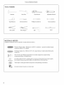
Tools and Materials
TOOLS
Needed
NEEDED
Hammer
Hob Saw
Tape Measu re
Sbt Screwdriver
Wire Cutter
Wire Stripper
MATERIALS
Adjustabb Wrench
PhHHpsScrewdriver
DrHI _-
Z
%20 Screwdriver
i
Level
NEEDED
(Additional materiab may be required to comply with bcal codes,)
Ebctrbal Supply CaNe - Minimum #14 AWG, 2 conductor, 1 ground, insulated copper
conductors rated 75°C or higher,
_>
Hot Water Supply Line - Minimum 3/8" O,D, copper tubing or metal braided dishwasher
....... supply line,
......
"_*s{_:
5
@}s
Shut-off valve and fittings appropriate for hot water supply line (copper tubing/
compression fitting, or braided hose),
90 ° elbow with 3/8" N, P,T, male threads on one leg, and sized to fit your water supply
<c_......
..... ;._"
,_>
:_;:
line (copper tubing/compression
fitting, or braided hose) on the other leg,
Teflon tape or other pipe thread compound to seal plumbing connections,
UL listed conduit connector or strain relief,
2
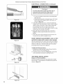
Materials Supplied
MATERIALS
SUPPUED
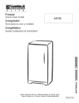
Accessory Parts Supplied
Accessory parts for your dishwasher come in one or more pUastic bags that are outlined bebw.
NOTE: Make sure you save aHthe bags until you have compbted your installation.
NOTE: Always use the suppibd or recommended hardware.
f Manual Set Bag
A ManuaU Set Bag is provided with each dishwasher and
includes:
A Use & Care instructions and installation
instructions (both manuab may be included
B
C
D
E
,nasingb"flip-styb'book
Quick
Reference Guide (sebct modeb)
ExtraTaH item SpdnHer
SHUand SHV installation Template (SHI and SHV
models only)
White Cotton Insulation Strip (SHY66C, SHX99A,
SH E66C, SH E99C, SHX57C and SHV57C models
f" Dishwasher Installation Kit
A Dishwasher Installation Kit is provided with each
dishwasher and includes:
F Toe Panel Screws (2 black machine screws)
Note: These screws are included, but not used on
models with the Toe Panel Installation Kit.
G Counter Top Mounting Brackets (2 '%" shaped metal
brackets)
H Mounting Bracket Screws (2 silver wood screws)
1 Rubber Drain Hose Adaptor (1 Mack rubber tube)
J
Hose Clamps ( 1 silver spring clamp to use to
attach the rubber adaptor to the Drain Hose and 1
gold screw clamp to attach the rubber adaptor to
K
L
M
_
;
r
@--
Wire Nuts (3 for electrical connection)
Electrical Junction Box Screws (2 silver
Leg Leveler Locking Screws (2 gold coarse
!h sadscrews!
f SHI/SHV Door Panel Installation
Kit
A Door Panel Installation Kit is provided with select
dishwashers that use a custom wood door panel and
includes:
N Plastic Caps (2)
0 Spring Tension Screws (2 larger silver machine
screws used to adjust the door springs to accommodate doors of different weights)
P Door Mounting Brackets (2 gold metal brackets
and 2 white plastic brackets used to mount the
custom door)
Q Door Mounting Bracket Screws (8 silver wood
£_5559
screws)
R
Door Mounting Screws (2 long silver screws used
@@ @,@
B
f Toe Panel Installation Kit
A Toe Panel Installation Kit is provided on models
SHY66C, SHX99A, SHE66C, SHE99C, SHX57C, and
SHV57C. These models have a special noise reducing
Toe Panel with the following mounting hardware:
S Toe Panel Screws (2 black screws used to attach
T
Black Plastic Base Access Panel Screws (2 long
silver screws used to attach the Black plastic
Base Access Pans! !o!he d!shwasher:
_J
3
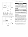
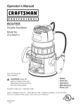
EncBosure Preparation
23-9/I 6"
I_(598mm)
I"
ElectricaJ Shock Hazard
To avoid eJectricaJ shock, make sure the water
supply and electrical suppJy are shut off before
installation or service.
ENCLOSURE
(89z}mrn)
PREPARATmON
mIR_mum
v
23-5/8"
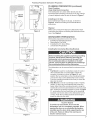
NOTE: This dishwasher is designed to be enclosed on the
top and both sides by standard residentiaU kitchen
cabinetry.
I
-
24-1/4"
(600-616
rY_f]q
Figure 1
clearance
between
dishwasher
Check
door
and wall --I
ElectricaJ Shock/Fire
Countertop
Figure 2
i\
i \
I
Figure 3
4
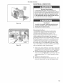
Select a location as close to the sink as possible for
easy access to water supply and drain lines.
For proper dishwasher operation and appearance, ensure
that the enclosure is square and has the dimensions
shown in Figure !.
if the dishwasher is to be installed in a corner, make sure
that there is adequate clearance to open the door. See
Figure 2,
\
\
Hazard
To avoid eJectric shock or fire, do not allow the
eJectricaJ and water supply Jines to touch.
Separate channeJs are provided under the
dishwasher (see page 10).
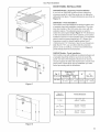
If the enclosure requires openings for the electrical supply
cable, hot water supply line, and dishwasher drain hose,
place them within the dimensions shown by the shaded
area of Figure 3 to avoid interference with the dishwasher
frame or other components. Make the openings for the
electrical supply cable and hot water supply line 1"
(25.4mm) diameter. Make the opening for the dishwasher
drain hose 1-1/4" (32mm) diameter. If the openings are
made through wood, sand them smooth. If the openings
are made through metal, make them large enough to
accommodate grommets or other protective sheaths with
inside diameters of 1" (25.4mm) for the electrical supply
cable and the hot water supply line, and 1-1/4" (32mm) for
the dishwasher drain hose.
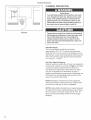
Electrical Shock Hazard
To avoid electdcaJ shock, do not work on an
energized circuit. Doing so could resuJt in serious
injury or death. Onty qualified electricians should
perform electrical work. Do not attempt any work
on the dishwasher etectric suppty circuit until you
are certain the circuit is
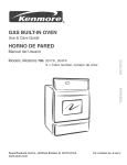
30 _E
(762mm)
21
EE
(533mm)
de-energized.
Figure 4
Fire Hazard
Dishwasher
Velts
120
E_ectrica_ Rating
Amperes
60
15
3"
Watts
1,450
(max)
A,,
1
( 75mm ° lOOmm
1.
To avoid a fire hazard, make sure electrical work
is properly installed. OnJy qualified electricians
shouJd perform eJectrical work.
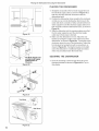
Electrica! Supply
The customer has the responsibility of ensuring that the
dishwasher electrical installation is in compliance with all
national and local electrical codes and ordinances. The
dishwasher is designed for an electrical supply of 120V,
60 Hz, AC, connected to a dishwasher-dedicated,
properly grounded electrical circuit with a fuse or breaker
rated for 15 amps. Electrical supply conductors shall be a
minimum #14 AWG copper wire rated at 75°C or higher.
Regardless of where the electrical supply cable enters the
enclosure, position the cable 21" (533mm) from the
enclosure's left side, as shown in Figure 4. Extend the
cable 30" (762mm) from the enclosure's back, as shown
in Figure 4.
3/8"-
( 8mm-
1/2"
_
13mm) I
Figure 5
.<
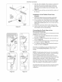
Remove 3" =4" (75mm =lOOmm) of the cable's outer
casing, as shown in Figure 5, then remove 3/8" - 1/2"
(9 - 13mm) of insulation from each wire, as shown in
Figure 5.
Plumbing
Preparation
PLUMBING
i355mm)
Hot Water
Supply
Line
Figure 6
PREPARATmON
Scald Hazard
To avoid being scaJded, do not perform any work
on a charged hot water tine. Serious injury could
result. Only qualified plumbers should perform
pJumbing work. Do not attempt any work on the
dishwasher hot water supply pJumbing until you
are certain the hot water supply is shut off.
Temperatures required for so(dedng and sweating
wil( damage the dishwasher's base and water inJet
va(ve. If plumbing lines are to be eo)dered or
sweated, keep the heat source at Jeast 6 inches
(152.4 ram) away from the dishwasher's base and
water in(et vaJve.
Hot Water Supply
The hot water heater should be set to deliver
approximately 120 ° F (49 ° C) water to the dishwasher,
Water that is too hot can cause some detergents to lose
effectiveness, Lower water temperatures will increase run
times, The hot water supply pressure must be between
15 - 145 psi (1 - 10 bars),
Hot Water Supply Plumbing
Install an easily accessible shut-off valve (not supplied) in
the hot water supply line, as shown in Figure 6, All solder
connections must be made before the water line is
connected to the dishwasher's water inlet valve, Water
may abe be supplied to the dishwasher by using a
stainless steel braided hose approved for dishwasher use,
Check with your local plumbing supply sources for the
proper hose and 90 ° elbow fitting,
NOTE: Regardless of where the hot water supply line
enters the enclosure, position the line 14" (355mm) from
the enclosure's left side, as shown in Figure 6,
NOTE: Decide whether braided hose or copper tubing wiii
be used for the hot water supply plumbing, and purchase
the correct type of hot water supply shut-off valve, 90 °
elbow, and necessary fittings for the hot water supply
6
Plumbing
Preparation/Dishwasher
AirGap
Preparation
PLUMBING
PREPARATmON
(continued)
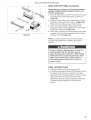
Drain Ptumbing
Under Sink Drain Connection
ff the dishwasher is to drain either directUy into the
househoUd drain pUumbing or through an air gap, install a
y-branch taHpbce under the sink as shown in Figure 7,
installing an Air Gap
if local ordinances require an air gap, as shown in
Figure 8, install it according to the manufacturer's
instructions,
Figure 8
Disposer
Make sure to remove the disposer's dishwasher drain
connection plug before connecting the dishwasher drain
hose, See Figure 9,
DISHWASHER
PREPARATmON
Dishwasher preparation involves four tasks:
Installing the Mounting Brackets
Installing the 90 ° elbow fitting
Junction Box Preparation
installing the Countertop
Mounting
Brackets
Before installing the supplied countertop mounting
brackets, decide which method of securing the
dishwasher into its enclosure wilt be used. Once
the mounting brackets are installed on the dishwasher, removing them is difficult and will damage
the mounting brackets and the dishwasher.
Figure 9
Step I
The dishwasher can be secured into its enclosure in two
Step 2
Figure 10
Step I
Figure 11
ways:
1 Top Mount is used for countertops made of wood or
other materials that can easily drilled, Orient the
mounting brackets as shown in Figure 10, and
position the two small tabs on the mounting brackets
over the two slots on the dishwasher's front corners,
Push the mounting brackets down firmly to insert the
tabs into the slots,
2 Side Mount is used for countertops made of marne,
granite, or other very hard materials that cannot be
easily drilled, Bend the mounting brackets along the
small hobs and in the same direction as the two small
tabs, Orient the mounting brackets as shown in Figure
11, and position the two small tabs on the mounting
brackets over the two slots on the dishwasher's front
corners, Push the mounting brackets down firmly to
insert the tabs into the slots,
Tip Over Hazard
To avoid a tip over hazard, do not use the
dishwasher until it is completeJy installed. When
opening the door on an uninstaHed dishwasher,
carefully open the door while supporting the rear
of the unit. Failure to fottow this warning can
resuff in serious injury.
Dishwasher
Preparation
DmSHWASHER
PREPARATmON
(continued)
Removing the Toe Pane1
FleguJar Toe PaneJ
The toe paneHis HooseHyattached with tape, Remove the
tape and puHH
the toe paneHaway from the dishwasher, Set
the toe paneHaside, HtwHHbe reinstaHHedHater,
PJastic Base Access Panel and Toe PaneJ (SHY660,
SHX99A, SHE660, SHE990, SHX570, and SHV570
modeJe only)
The pHasticbase access paneHand toe paneHare in pHace
on the dishwasher, but are not attached, Remove the toe
paneHfirst, as shown in Figure 12, then remove the
pHastic base access paneH,as shown in Figure 12,
Toe
PaneH
Figure 12
Installing the 90 ° Elbow Fitting
NOTE: The 90 ° eHbowfitting is not suppHied with the
dishwasher, and must be purchased separateHy, Hfthe
dishwasher's hot water suppHy Hineis to be copper tubing,
make certain the eHbowhas a compression fitting,
AppHyTeflon tape or other pipe seaHantwhen required,
Orient the hot water suppHyconnection Hegof the eHbow
toward the channeH opening in the dishwasher base, See
Figure 13,
Junction Box Preparation
1 Remove junction box cover (see Figure 14) by HiRing
the junction box cover up and off,
2
Remove the strain reHiefpilate by removing the screw
at the back of the junction box, as shown in Figure
15 and sHidingthe strain reHiefpilate out,
3
Set the junction box cover, strain reHiefpilate, and
screw aside, They wiHH
be re-instaHHedHater,
Figure 13
Figure 14
8
Figure 15
Door Paneminstallation
.
; ram) _
23-1/16"
(5s6
J
Figure 16
PANEL
mNSTALLATmON
SH U/SH E ModeJs - Accessory Panel lnstaJtation
Ufyou have an SHU/SHE modeUand have ordered an
accessory paneUkit, install the paneUprior to sliding the
dishwasher into pUace.The paneUdimensions are shown in
Figure 16.
1/4" max,
_
DOOR
SHI Modets - Panet Installation
SHUmodeUscome with additionaU mounting hardware and
a tempUate sheet with installation instructions. The stain°
UesssteeUmodeUs of the SHUseries aUsocome with two
extension pieces. The extension pieces are used to
match the control panel height (Figure 17, "B" dimension)
to the horizontal drawer line of the cabinets, and must be
installed as shown in on the template sheet. The standard
piece is used for drawer heights up to 6" (152mm); the
long piece is used for drawer heights greater than 6"
(152mm) but 6o7/16" (164mm) or less. If you r drawers are
taller than 6o7/16", you can either slide the extension
piece in as far as it will go, or remove it and fit the door
panel directly below the control panel.
SIll/SHY Models - Panel lnstaJlation
SHV models come with additional mounting hardware and
a template sheet that will show you how to mount the
panel. One side of the template shows how to mount a
one piece panel; the other side shows how to mount a two
piece panel. Decide which type of installation you want
before proceeding with the installation.
C
A
Extension "A"
Max, oMino
Fig. 17
Dimension
Standard
"B ....
Long
Max,=Mino
5/16- 11/16" i11/16- 1 1/8" 55/!6"
(8-18mm) i(18 - 29mm) (!35mm)
SHI Only
C"
55/8-67/16"
(143 - 164mm)
Figure 17
Fig. 18
Dimension
Panem Dimension
D (SHJ)
20 11/16" - 25"
(526turn - 635mrn)
E
27 3/!6" - 30 5/16"
(SIll & SHV)
(690mm
- 770mm)
F
(SHI & SHV)
23 [€/16" - 23 3/8"
(589mrn - 594turn)
PlacingtheDishwasher/Securing
theDishwasher
PLACmNG THE DISHWASHER
1 Straighten and position the hot water supply line and
the electrical supply cable as shown in Figure 19 so
that they wiii align with their channels under the
dishwasher base,
_L
2 Position the dishwasher close enough to the enclosure
so that you can run the dishwasher drain hose to the
under sink drain connection, Make certain that the hot
14"
355mm)
_/
J
Figure 19
SECURING
Hot Water Supply Line
and Electrical Supply
Cable Position in
Channels
J
Figure 20
Figure 21
f
Figure 22
10
water supply line and the electrical supply cable are in
their channels under the dishwasher base, as shown in
Figure 20,
3 Slide the dishwsher into the opening making sure that
the hot water supply line and the electrical supply
cane stay in their proper channels,
4 Make sure the dishwasher is level, Adjust the rear
leveler by turning the center screw at the front of the
dishwasher, as shown in Figure 21a, Turning the screw
clockwise raises the rear of the dishwasher, Adjust the
front levelers by turning them with a screwdriver, as
shown in Figure 21b, Turning the levelers to the right
raises the dishwasher, if additional height is needed,
shims may be added under the leveler feet,
THE DISHWASHER
1 Drive the mounting screws through the hobs in the
mounting brackets as shown in Figure 22 for Top or
Side Mount.
Drain Hose Connection
2 After the unit is instafled in the enclosure, bvebd and
secured, lock the two front bg bvebrs in place by
driving the enclosed bg bvebr locking screws into
each screw boss located in front of the bvebrs, See
Figure 23,
3 Tighten screws until they are flush with the surface of
the bosses,
Leg
Leveler
Locking
Screw
mnstaHation of the Rubber
Adaptor
Y
• Screw
Boss
Figure 23
Drain Hose
1 Obtain the Rubber Drain Hose Adaptor and the two
hose damps from the Dishwasher Instaflation Kit,
2 On one outside end of the Rubber Drain Hose Adapter
is a raised groove, Insert the drain hose into the end
without the raised groove. Be sure to fully insert the
drain hose,
3 Secure the connection with the Silver Spring Clamp,
4 Use the Gold Screw Clamp to attach the Rubber Drain
Hose Adaptor to the house plumbing,
Connecting
Household
the Drain
P_umbing
Hose to the
The dishwasher drain hose may be connected to the drain
plumbing in one of four ways:
1 Directly to the undersink dishwasher drain connection,
as shown in Figure 24,
2 Directly to a disposer dishwasher drain connection, as
shown in Figure 25,
3 To the undersink dishwasherdrain connection through
an air gap, as shown in Figure 26,
4 To a disposer dishwasher drain connection through an
air gap, as shown on Figure 27,
information on installing air gaps and disposers can be
found in the Ptumbing Preparation section of this
manual,
Figure 24
Figure 25
NOTE: if the dishwasher drain hose is to be connected to
a disposer dishwasher drain connection, remove the plug
from the disposer's dishwasher drain connection.
Use the supplied Rubber Drain Hose Adaptor and Drain
Hose Clamps to connect the dishwasher drain hose to the
plumbing drain connection. Use the spring clamp to
secure the Rubber Drain Hose Adaptor to the dishwasher
drain hose. Use the screw clamp to secure the Rubber
Drain Hose Adaptor to the plumbing drain connection.
The dishwasher drain hose must have one place along its
length that is securely attached 20 inches above the
cabinet floor,
Figure 26
Figure 27
11
Hot Water Connection
HOT WATER
CONNECTmON
Scald Hazard
To avoid being scaJded, do not perform any work
on a charged hot water tine. Serious injury could
result. Only qualified plumbers shouJd perform
pJumbing work. Do not attempt any work on the
dishwasher hot water supply pJumbing until you
are certain the hot water supply is shut off.
NOTE: Make certain that the correct 90 ° eUbowfitting (not
supplied) for the hot water supply line has been purchased and installed on the dishwasher as described in
the Dishwasher Preparation section of this manual,
The hot water supply line may be connected to the
dishwasher in one of two ways:
1 With braided hose,
2 With copper tubing,
Braided Dishwasher Suppty Hose
After connections are made turn on the hot water supply
to check for leaks,
NOTE: Braided dishwasher supply hoses can also be
used to extend pre-existing dishwasher water supply
lines,
Copper Tubing
Temperatures required for soJdedng and sweating
writ damage the dishwasher's water inlet vaJve. If
ptumbing Hnes are to be soldered or sweated,
keep the heat source at Jeast 6 inches (152.4 ram)
away from the dishwasher's water intet vaJve.
, if using a solder joint instead of a compression fitting,
be sure to make all solder connections before
connecting the water line to the dishwasher,
* Make certain there are no sharp bends or kinks in the
water line that might restrict water flow,
* Be sure to use pipe thread compound or Teflon tape to
seal the connection when required,
, Before connecting the copper hot water supply line to
the dishwasher, flush it with hot water to clear any
foreign material,
* Turn on the water supply to check for leaks after
NOTE: Do not use pipe sealant on compression fittings,
12
Electrical
Connection
ELECTFiICAL
CONNECTmON
Electrical Shock Hazard
To avoid ebctricaJ shock, do not work on an
energized circuit. Doing so could result in serious
injury or death. OnJy quaJified eJectricians shouJd
perform ebctrical work. Do not attempt any work
on the dishwasher electric suppJy circuit until you
are certain the circuit is de-energized.
Fire Hazard
Figure 28
To avoid a fire hazard, make sure eJectricaJ work
is properly installed. Only qualified electricians
shouJd perform electricaJ work.
Casing
Figure 29
Grounding instructions
The dishwasher must be properly grounded before
operating, This appliance must be connected to a
grounded metal permanent wiring system, or an
equipment grounding conductor must be run with the
circuit conductors and connected to the equipment
grounding terminal or lead on the dishwasher, Make sure
that the dishwasher is connected to a suitable ground in
compliance with all local codes or, in the absence of a
local code, with the NATIONAL ELECTRICAL CODE in
the United States or the CANADIAN ELECTRIC CODE
C22,1-latest edition in Canada as well as any provincial/
state or municipal or local codes that apply,
1 Retrieve the strain relief plate, and install a strain relief
(not supplied) into the opening on the strain relief plate,
NOTE: Orient the strain relief as shown in Figure 28,
2 Pass the electrical supply cable through the strain
relief, as shown in Figure 29, Make sure the outer wire
casing extends about 1/2" (13mm) through the strain
relief,
3 Tighten the strain relief screws,
4 Slide the strain relief plate into the junction box, and
secure it to the junction box with the supplied screw,
13
EmectricalConnection/Door
-_
Tension Adjustment/Base and Toe Panel
ELECTRICAL
CONNECTmON
(continued)
Fire Hazard
To avoid a fire hazard, make sure there are no
toose eJectrical connections. Make sure aH
etectricaJ connections
are properly
made.
o Do not pre-twist the wires before connecting them
with wire nuts,
o Extend the dishwasher's stranded wires 1/8" (3mm)
beyond the power supply cable's solid wires, as
shown in Figure 30,
5 Using the supplied wire nuts, connect the electrical
supply wires to the dishwasher's wires, black to black,
white to white, and green or bare, Make certain that
the insulated wires show no bare wire from the
bottoms of the wire nuts, Gently tug the wires to make
certain they are securely connected,
6 Press the wires into the junction box as shown in
Figure 31, Make certain that the wire nuts do not
loosen,
7 Place the cover on the junction box and secure it to
the junction box with the supplied screw,
DOOR
TENSION
ADJUSTMENT
(only
on SHI
and SHV mode_s with custom
door pane_s)
After the dishwasher and custom door panel are installed,
open and close the door several times to make sure that
it does so with ease, If the door falls open too quickly,
the spring tension needs to be adjusted,
Figure 31
To Adjust the Spring Tension:
1 Obtain the provided Spring Tension Screws from the
SHI/SHV Door Panel Installation Kit,
2 insert the screws as shown in Figure 32, Turning the
screw clockwise increases the spring tension,
TOE PANEL
J
Figure 32
Figure 33
14
mNSTALLATmON
Regutar Toe Panel installation
Use the toe panel screws from the Dishwasher Installa°
tion Kit and a %20 screwdriver to install the toe panel as
shown in Figure 33,
Base and Toe Pane,/Final
Instructions
BASE
AND TOE PANEL
(Continued)
PJaetic Base Access PaneJ and Toe PaneJ installation
(SHY66C, SH×99A, SH E66C, SHE99C, SH×57C, and
SHV57C modete only)
1 PUacethe PUastb Base Access PaneUunder and up the
front bottom paneUof the dishwasher, as shown in
Figure 34a,
2 insert the PUastb Base Access PaneUscrews into the
PUastb Base Access PaneU, as shown in Figure 34b,
Tighten the PUastb Base Access PaneUScrews,
3 PUace the Cotton UnsuUationStrip under the unit,
between the bottom of the Plastic Base Access Panel
and the floor, as shown in Figure 34c,
4 Attach the Toe Panel to the Plastic Base Access Panel
using the Toe Panel Screws included in the Toe Panel
Installation Kit, See Figure 34d,
NOTE: You will not use the normal Toe Panel Screws
included in the Dishwasher Installation Kit on these
models,
In some conditions, Hydrogen gas can form in a
hot water system that has not been used for
weeks. Hydrogen gas is e×pJoeive. Before filling
a dishwasher from a system that has been off for
weeks, run the water from a nearby faucet in a
wett ventilated area untit there is no sound or
evidence of gas.
FINAL
mNSTRUCTmONS
1 Energize the dishwasher power supply circuit,
2 Consult the Dishwasher Use and Care Manual, and run
the dishwasher through one complete cycle, if the
dishwasher does not operate properly, refer to the SelfHelp section of the Use and Care Manual, if the
dishwasher still does not operate properly, refer to the
Customer Service Section of the Use and Care
Manual,
15
Customer
CUSTOMER
Service
SERVmCE
Your Bosch dishwasher requires no special care other than that described in the Care and Cleaning section of the Use
and Care Manual, if you are having a problem with your dishwasher, before calling for service please refer to the SelfHelp section of the Use and Care Manual, if service is necessary, contact your dealer or installer or an authorized
service center, Do not attempt to repair the appliance yourself, Any work performed by unauthorized personnel may void
the warranty,
if you are having a problem with your Bosch dishwasher and are not pleased with the service you have received, please
take the following steps (in the order listed below) until the problem is corrected to your satisfaction,
1, Contact your installer or the Bosch Authorized Service Contractor in your area,
2, E-mail us from the customer service section of our website, www,boschappliances,com,
3, Write us at:
BSH Home Appliances, Corp,
5551 McFadden Avenue
Huntington Beach, CA 92649
4, Call us at 1°800°944°2904,
Please be sure to include (if you are writing), or have available (if you are calling), the following information:
o Model number
o Serial number
o Date of original purchase
Date the problem originated
Explanation of the problem
Also, if you are writing, please include a daytime phone number where you can be reached, You will find the model and
serial number information on the label located on the right-hand side of the inner door of your dishwasher, see Figure 1,
it will look similiar to this:
1
1
Please make a copy of your invoice and keep it with this manual,
© BSH Homo Appliances
16
Corporation
2005 • Litho U,S,A,
07/04
Notes
Notes
Notes
© BSH Home Appliances
90 00 06 37 16 (8504)
Corporation
2005 • Litho U,S,A,
07/04