1
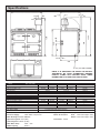
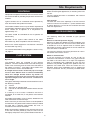
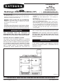
Installation
and
Servicing
Instructions
Heatranger 480AG (CF)/480AL (CF)
Consumer Protection
As responsible manufacturers we take care to make sure that our
products are designed and constructed to meet the required safety
standards when properly installed and used.
FOR USE IN GB & IE
be interpreted as being injurious to health and safety, see below for
information.
Firebricks, Fuel beds, Artificial Fuels - when handling use
disposable gloves.
Fire cement - when handling use disposable gloves.
Glues and Sealants - exercise caution - if these are still in liquid form
use face mask and disposable gloves.
Glass Yarn, Mineral Wool, Insulation Pads, Ceramic Fibre,
Kerosene/Gas Oil - may be harmful if inhaled. May be irritating to
skin, eyes, nose and throat. When handling avoid contact with skin
or eyes. Use disposable gloves, face-masks and eye protection. After
handling wash hands and other exposed parts. When disposing of
the product, reduce dust with water spray, ensure that parts are
securely wrapped.
IMPORTANT NOTICE: PLEASE READ THE ACCOMPANYING
WARRANTY. Any alteration that is not approved by AGA could
invalidate the approval of the appliance, operation of the warranty
and could affect your statutory rights.
Important
This appliance may contain some of the materials that are indicated
It is the Users/Installers responsibility to ensure that the necessary
personal protective clothing is worn when handling where applicable,
the pertinent parts that contain any of the listed materials that could
central heating boiler section, providing heating and hot
water, whilst the other burner provides heat to the cooker.
INTRODUCTION
THIS APPLIANCE MUST BE INSTALLED IN
ACCORDANCE WITH THE RULES IN FORCE AND
USED ONLY IN A SUFFICIENT VENTILATION SPACE.
REMEMBER, when replacing a part on this appliance,
use only spare parts that we require. Do not use
reconditioned or copy parts that have not been clearly
authorised by AGA.
USE ONLY ON FULLY PUMPED SYSTEMS
This Rayburn Gas combination appliance is combined
cooker and hot water boiler providing central heating and
domestic hot water in addition to special cooking facilities.
It is available in open flue form, operating on natural
draught, the boiler being designed for use in fully pumped,
open or sealed systems. Two separate independent
controlled gas burners provide heat. One burner for
REGULATIONS
In the interests of safety all gas appliances should be
installed by competent persons, in accordance with the
regulations in force.
DESN 512129
PLEASE READ THESE INSTRUCTIONS BEFORE INSTALLING THE APPLIANCE
[email protected]
1
02/13 EINS 512112
Contents
SECTION
CONTENTS
SITE REQUIREMENTS
SPECIFICATIONS
LOCATION
GAS SUPPLY
ELECTRICAL SUPPLY
CONTROLS
FLUE SYSTEM
AIR REQUIREMENTS
WATER CIRCULATION SYSTEM
INSTALLATION INSTRUCTIONS
CLEARANCES
PRELIMINARY INSTALLATION
GAS CONNECTION
WATER CONNECTIONS
SYSTEM SUITABILITY
COMBUSTION DISCHARGE SAFETY DEVICE
ELECTRICAL CONNECTIONS
ELECTRICAL CHECKS
8
8-9
10
10
10
10
11
11
COMMISSIONING
ELECTRICAL INSTALLATION
WATER CIRCULATION SYSTEM
COMMISSIONING THE COOKER AND BOILER
INSTRUCT THE USER
LIGHTING THE PILOT
BOILER OUTPUT SETTING
MAIN BURNER LIGHTING
13
13
13
13
13
13
14
SERVICING
ANNUAL SERVICING
SERVICE SCHEDULE
PRE-SERVICE CHECK
HOTPLATE CLEANING
BURNER ACCESS
BURNER CLEANING
HEAT EXCHANGER
COMBUSTION CHAMBER INSULATION
FLUE CLEANING
RE-ASSEMBLE THE APPLIANCE
15
15
16
16
16
17-18
19
19
19
20
REPLACEMENT OF PARTS - COOKER
TO FIT NEW BURNER
TO FIT NEW BURNER INJECTOR
ELECTRICAL COMPONENT ACCESS
OVEN CONTROL THERMOSTAT
COOKER OVERHEAT THERMOSTAT
21
21
22-23
24
24
REPLACEMENT OF PARTS - BOILER
GAS VALVE
PILOT INJECTOR
BURNER
BURNER INJECTOR
BOILER THERMOSTAT
BOILER OVERHEAT THERMOSTAT
COMBUSTION DISCHARGE SAFETY DEVICE
SEALED SYSTEMS
SEALED SYSTEMS
2
PAGE
3
4
4
4
6
6
6
7
25
25
26
26
26
27
27
28
29
Specifications
585
905
67
102
118
1355
1240
125
446
940
910
50
38
542
R 1/2 (1/2” BSP TAPER)
NOTE: IT IS ADVISABLE TO CHECK THE ACTUAL
SIZE/WIDTH OF YOUR CUPBOARDS BEFORE
FINALLY FIXING ANY KITCHEN UNITS SINCE
ENAMELLED CAST IRON CAN VARY IN SIZE.
480AG
TOTAL
NAT. GAS (G20)
MIN.
Max. Heat Inputs - Gross
Max. Heat Inputs - Net
Inlet Pressure
Marking - Injector Size
Max. Boiler Output
Min. Boiler Output
480AL
BOILER
MAX.
MIN.
COOKER
MAX.
23.5kW
30.5kW
21.0kW
27.5kW
2.82m3/h
1.17mm x 15
23.4kW at 13mbar burner pressure
17.6kW at 8mbar burner pressure
PROPANE (G31)
Max. Heat Inputs - Gross
Max. Heat Inputs - Net
Inlet Pressure
Marking - Injector Size
Max. Boiler Output
34kW
41.0kW
30.5kW
37.0kW
20mbar
10.7 KW
9.6 KW
1.02m3/h
BRAY CAT 28/600
TOTAL
MIN.
MAX
35.8kW
40.7kW
33.0kW
37.4kW
37mbar
COOKER
Min. Boiler Output
BOILER
MIN.
MAX.
25.6kW
30.5kW
23.5kW
28kW
1.09m3/h (2103g/h)
0.75mm x 15
23.4kW at 32.5mb burner pressure
10.2kW
9.4kW
0.37m3/h (700g/h)
4016
17.6 kW at 20.5mbar burner pressure
Gas Connection
R1/2 (1/2” BSP TAPER)
Appliance weight
Electrical Supply
230V~50Hz 3 amp Fused
Boiler Connections:
Max. Working Pressure of Boiler:
Flue Outlet - 125mm
Sealed System 2.60 bar (26.0m)
82ÞC + 3ÞC
Water Capacity
0.6 litre
Flow
22mm O/D Copper Tube
Return 22mm O/D Copper Tube
Open Vent System 3 bar (30m)
Max. Water Temp.
330Kg
3
Site Requirements
LOCATION
GAS SUPPLY
The appliance must be installed on a solid level floor or base
of incombustible material which is capable of supporting the
total weight.
Pipework from the meter to the appliance must be of
adequate size. It is recommended that ø22mm minimum
diameter copper tubing is used. Do not use pipes of a
smaller size than the appliance gas connection. The
complete installation must be tested for soundness and
purged in accordance with the regulations in force.
The location chosen for the appliance must permit installation
and the provision of a satisfactory flue and an adequate air
supply. The location must also provide space for servicing and
air circulation around the appliance.
Between wall and LH side of appliance
10mm
Between wall and RH side of appliance
10mm*
*SHOULD THE WALL PROJECT BEYOND THE FRONT OF
THE APPLIANCE, WHEN IT MUST BE INCREASED TO
50MM (SEE FIG. 1A, 1B).*
Above the raised insulating cover handle
60mm
ELECTRICAL SUPPLY
NOTE: GAS AND WATER CONNECTIONS ARE LOCATED
ON THE LH SIDE OF THE APPLIANCE. INSTALLERS
MUST MAKE PROVISION FOR ACCESS TO THESE
CONNECTIONS DURING INSTALLATION.
External wiring must be correctly earthed, polarised and in
accordance with current regulations. The main supply
required is 230V, 50Hz fused at 3A.
In addition, adequate clearance must be available at the front
of the appliance to enable it to be operated and serviced. Flue
pipes and fittings must not be closer than 25mm to
combustible materials and where passing through a
combustible partition such as a ceiling or roof, must be
enclosed in a non-combustible sleeve providing an air space
of at least 25mm.
NOTE: The method of connection to the electricity supply
must facilitate complete electrical isolation of the
appliance, preferably by the use of a fused three pin plug
and unswitched shuttered outlet. Alternatively, connection
may be made by a via a fused double-pole isolator with a
contact separation of at least 3mm in all poles and serving
the appliance and system control only.
Spaces around flue pipes passing through walls or floors
should be sealed against the passage of smoke and flame.
Where the cooker is to stand in a recess or against a wall
which is to be tiled, in no circumstances should the tiles
overlap the cooker top plate.
NOTE: SMOKE/SMELL EMITTED DURING INITIAL USAGE.
Some parts of the cooker have been coated with a light
covering of protective oil. During initial operation of the cooker,
this may cause smoke/smell to be emitted and is normal and
not a fault with the appliance, it is therefore advisable to open
doors and or windows to allow for ventilation. Lift the insulating
lids to prevent staining the linings.
4
10mm
10mm
WATER
CONNECTIONS:
INSTALLER MUST MAKE
PROVISION
TO
GAIN
ACCESS TO 22mm COPPER
FLOW AND RETURN PIPE
DURING INSTALLATION
R 1/2 (1/2” BSP) GAS
CONNECTION
MINIMUM GAP ON RIGHT HAND SIDE
MINIMUM GAP ON LEFT HAND SIDE
Fig. 1A
50mm
WALL PROJECTING
APPLIANCE
THE
FRONT
OF
THE
Fig. 1B
5
Site Requirements
CONTROLS
a baffle plate, etc is fitted in the flue it must be removed
before connecting the appliance to, or inserting a liner into
the flue.
Independent temperature controls with time switch control
are recommended for providing temperature comfort from
radiators.
The flue should terminate in accordance with relevant
recommendations.
Flue Terminal
The total free area of the openings in the flue terminal
must be a minimum of 24,546mm2 = (cross sectional area
of 125mm dia flue x 2) in the UK GC1 and GC2 terminals
meet this requirement.
Typical controls can be motorised valves operated by
room thermostat and cylinder thermostat.
Thermostatic radiator valves may be fitted if required and
consideration should be given to fitting a frost thermostat
which should set to operate at a temperature of
approximately 4ºC.
AIR REQUIREMENTS
The boiler should be controlled so that it operates on
demand only.
The following notes are intended to give general
guidance:-
Operation of the system under control of the boiler
thermostat only, does not produce the best efficiency.
Kitchen or Internal Space Air Supply
Wherever an open flue appliance is to be installed it must
have a permanent air vent. This vent must be either direct
to outside air or to an adjacent room or internal space
which itself must have a permanent air vent of at least the
same size direct to outside air.
Refer to the control equipment manufacturer’s literature
for information e.g wiring.
The internal boiler/cooker wiring diagram is shown in Fig.
10, page 12.
The minimum effective area of the permanent air vent in
the outside wall must be 147cm2.
FLUE SYSTEM
Effect of an Extract Fan
It may be necessary to increase air vent by 50% or
consult fan manufacturers. If there is any type of extract
fan fitted in the same room as an open flue appliance
there is a possibility that if adequate air inlet are from
outside is not provided, spillage of the products from the
appliance flue could occur when the extract fan is in
operation. Where such installations occur, a spillage test
must be carried out and any necessary remedial action
taken.
Open Flue
The following notes are intended to give general
guidance. The cross sectional area of the flue serving the
cooker must not be less than the area of the flue outlet of
the cooker (12,273mm2). If flue pipe is to be used it must
not be less than 125mm internal diameter.
A straight vertical section of the flue pipe of a length
not less than 600mm must be utilised immediately
above the draught diverter before any bends are
used. Bends not less than 135º must not be used. The
equivalent height of the flue must be a minimum of
3m in length.
Flue pipes and fittings should be constructed from one of
the following materials:(a)
(b)
(c)
Cement
Aluminium or stainless steel
Cast iron or mild steel acid resistant vitreous enamel
lined.
If a chimney is to be used, it should be one that is
composed, of or lined with, a non-porous acid resistant
material.
A flue pipe constructed in (a) to (c) above, should form the
initial connection to lined chimneys.
Where a chimney is to be used, which is not composed of
or lined with a non-porous acid resistant material, it should
be lined with a stainless steel flexible flue liner, in
accordance with relevant standards.
Before connecting the appliance to or inserting a liner into
a flue that has been previously used, the flue must be
thoroughly swept clean of any soot and loose materials. If
6
Site Requirements
WATER CIRCULATION SYSTEM
In a combined central heating and domestic hot water
system, the hot water storage vessel must be of the
indirect cylinder type. The hot water storage vessel should
be insulated with not less than 75mm thick mineral fibre or
its equivalent.
Cisterns and pipework should not be situated in areas
which may be exposed by freezing conditions and should
be insulated.
Draining taps must be located in accessible positions
which permit the draining of the whole system, including
the heat storage vessel.
The appliance boiler section should be connected to
cistern water supply, subject to a maximum head of 3 bar
(30m), minimum of .1 bar (1m).
300
The heating system must be designed (and adjusted if
necessary) to give temperature differential across the
boiler at full output of 10-14ºC.When horizontal runs are
used the pipes should rise upwards in the direction away
from the appliance.
600
FIG. 2 Pressure Loss Curve
Sealed System Requirements
See Page 28 and 29.
Circulating Pump
It is recommended that the selected pump be sized to suit
the boiler pressure loss (see Fig. 2) and therefore
adequate to give the required temperature differential
between the flow and return.
The pump should be able to meet the requirements of the
system design and fitted in a readily accessible position.
Isolating Valves
Isolating valves (preferably of the keyless type) must be
fitted to the inlet and outlet of the circulating pump to
facilitate service and replacement of pump without
draining the system.
Inhibitor
A corrosion inhibitor MUST be added to the heating
system to protect the heat exchanger and pipework.
Inhibitor must also be replaced if the system is drained
after installation. As a precaution the heating system
MUST also be flushed out prior to the addition of the
inhibitor to ensure any flux, debris is removed.
7
900
1200
1500
Installation Instructions
CLEARANCES
The appliance is floor mounted. The space in which the
appliance is to be fitted must have the following minimum
dimensions:Between wall and LH side of appliance - 10mm
Between wall and RH side of appliance - 10mm*
*SHOULD THE WALL PROJECT BEYOND THE FRONT
OF THE APPLIANCE, WHEN IT MUST BE INCREASED
TO 50MM (SEE FIG. 1A, 1B).
Above the raised insulating cover handle - 60mm
In addition, adequate clearance must be available at the
front of the appliance to enable it to be operated and
serviced.
FIG. 3
DESN 512141 A
PRELIMINARY INSTALLATION
The appliance is delivered assembled with the exception
of the following items which are supplied separately
packed and require assembly.
1. Draught Diverter Assembly
See Fig. 3.
2. Appliance Rear Distance Bracket
(for use when appliance is
installed (25mm) away from a
rear wall of combustible
material). See Fig. 4.
m
25m
COMBUSTIBLE
WALL LINE
BRACKETS
SCREWED TO
BACK EDGE OF
BOTH SIDE PLATES
WHEN
COMBUSTIBLE
WALL IS UTILISED
ON INSTALLATION
3. Hand Rail
The handrail brackets are held on the front ends of
the cooker top-plate casting. Remove the travel nuts
and replace with the handrail brackets ensuring the
fibre protecting washers are in position. Insert the
handrail with fitted endcaps in to the brackets,
positioning them correctly, and tighten the locating
bolts (Fig. 5).
8
FIG. 4
DESN 512142
FIG. 5
DESN 510454 ‘A’
Installation Instructions
Site Location
1. Remove the appliance assembly from the transit
wooden pallet by the temporary location of a sloping
ramp board between the pallet and the floor. With the
appliance on the floor, lift the front of the appliance
(manually or crowbar) and insert a 32mm x 1m long
tube between the front of the appliance base plate
and the floor.
9
1
Draw the tube balanced appliance forward until the
tube is at the rear of the appliance and then insert a
second similar tube at the front of the appliance,
between the base plate and the floor. The tube
supported appliance can now slowly be “rolled”
across the floor and positioned with its back against
the wall, and in its intended location for flue
connection.
2
8
3
7
Using a crowbar at the rear of the appliance base
plate, take the weight of the appliance on the
crowbar and remove the rear rolled tube, followed by
similar action on the front tube.
5
2. Assemble and locate the flue draught diverter
assembly on flue spigot as follows (See Fig. 6):-
4
1. Ensure baffle plate is located with ‘front’ stamping
towards front of cooker.
6
2. Ensure C.D.S.D. is correctly located in C.D.S.D. in
phial clip.
NOTE: IT IS RECOMMENDED THAT A “SLIP” OR
“SPLIT” ADAPTOR IS FITTED BETWEEN THE
DIVERTER FLUE SOCKET AND FLUE PIPE TO
FACILITATE POSSIBLE FLUE DISCONNECTION
AFTER COMMISSION.
NOTE: INCORRECT FITTING OF COMBUSTION
DISCHARGE SAFETY DEVICE COULD ALLOW
PRODUCTS TO LEAK INTO THE ROOM UNDER
ADVERSE CONDITIONS.
KEY
Connect the flue system in accordance with standard
practice.
1.
2.
3.
4.
5.
6.
7.
8.
-
FLUE PIPE
HOOD
TOP SPACER - SHORT
BOTTOM SPACERS - LONG
BAFFLE
SPIGOT
COMBUSTION DISCHARGE SAFETY DEVICE (C.D.S.D.)
COMBUSTION DISCHARGE SAFETY DEVICE PHIAL
CLIP
9. - CDSD PHIAL BRACKET
FIG. 6
9
DESN 512141 A
Installation Instructions
GAS CONNECTION
1. Connect the gas supply to the 1/2” BSP tapered
thread on the left hand side of the appliance (See
Specifications, page 3).
2. Test the whole of the gas installation including the
meter and purge in accordance with the relevant
recommendations.
WATER CONNECTIONS
The two flow and return (22mm O/D Copper Tube)
connections are located towards the rear edge of the
appliance left hand side panel.
CDSD RESET
BUTTON
Fig. 6A
SYSTEM SUITABILITY
THIS BOILER IS SUITABLE FOR FULLY PUMPED
SYSTEMS ONLY.
For optimum operating conditions the heating system into
which the boiler is installed, should include a control
system.
Such a system will include a time switch and a room
thermostat and/or cylinder thermostat.
The boiler should be controlled so that it is operated on
demand only.
Operation of the system under control of the boiler
thermostat only does not produce the best efficiency.
Refer to the control equipment manufacturer’s literature
for information e.g. wiring.
The internal boiler/cooker wiring is shown in Fig. 10.
COMBUSTION DISCHARGE SAFETY
DEVICE
For safety purposes a combustion discharge safety
device is fitted. This will only operate under adverse flue
conditions. If the switch has operated, it should be pushed
in to reset. If this problem persists contact your local
engineer to determine and rectify the cause. It is important
not to reset more than once as this may indicate a flue
blockage.
WARNING: The combustion discharge safety device
must not be interfered with or rendered inoperative, as
this could interfere with the safe operation of the
appliance and invalidate the appliance warranty.
10
DESN 511788
Installation Instructions
ELECTRICAL CONNECTIONS
Supply cable - PVC insulated three core 85ºC rated
300/500V .75mm .
2
To connect the electrical wiring to the appliance.
Make electrical connections to terminal strip as wiring
diagram.
Remove the plinth cover at the bottom of the appliance
(See Fig. 7 ).
Fit supply and pump cables to the terminals as shown in
Fig. 9. Ensure that the appropriate cable clamp is used.
The permanent live MUST be connected to the terminal
marked L.
FIG. 7
DESN 511767
If a time switch is fitted to the boiler then the system live
MUST be connected to the terminal marked BSL.
NOTE: The link between terminals L1 and BSL MUST be
removed to ensure correct operation of the time switch. If
the time switch is fitted to the cooker then the switched
live MUST be connected to the terminal marked CSL.
NOTE:- The link terminals L1 and CSL MUST be removed
to ensure correct operation of the time switch.
Refit the terminal cover plate.
WARNING
THIS APPLIANCE MUST BE EARTHED, EXTERNAL
CONTROLS AND THE APPLIANCE MUST BE
SUPPLIED VIA THE SAME PLUG AND SOCKET OR
ISOLATOR.
TERMINAL STRIP
FIG. 8
ELECTRICAL CHECKS
Check to ensure electrical safety should be carried out by
a qualified engineer.
FIG. 9
11
DESN 511769
Installation Instructions
FIG. 10
12
Commissioning
ELECTRICAL INSTALLATION
LIGHTING THE PILOT
Checks to ensure electrical safety should be carried out
by a competent person, ie. earth continuity, polarity and
resistance to earth.
Boiler (see Fig. 11)
This appliance is fitted with an automatic ignition unit that
will light the main burner on demand. Should button K
(see Fig. 11) be illuminated press button, this will allow the
burner ignition to continue, should the button illuminate
again this will indicate a fault on the boiler burner. Contact
your local Gas Safe Registered engineer to correct the
fault.
WATER CIRCULATION SYSTEM
The whole of the system should be thoroughly flushed out
with cold water without the pump in position. Ensure that
all valves are open. With the pump fitted, the system
should be filled.
Cooker (see Fig. 11).
Press in and hold the cooker flame failure override button
C allowing a few seconds for the gas to reach the cooker
pilot. Press the piezo ignitor button D and the pilot burner
will light.
Vent all heat emitters and check for water soundness.
COMMISSIONING THE COOKER
AND BOILER
Continue to hold the button in for 15 seconds after the
pilot has been lit so that when the button is released, the
pilot should remain alight.
Isolate electricity at the wall socket. Turn the cooker and
boiler control knob to off.
If it does not, WAIT 3 MINUTES then repeat the
procedure.
After ensuring gas is available to the appliance, loosen
joint and purge any air from the supply pipe.
BOILER OUTPUT SETTING
WARNING: NO SMOKING OR NAKED LIGHTS.
SEE FIG. 11
Tighten joint and check gas service cocks are in the ON
position. Check for gas soundness up to the gas valves.
(See Fig. 11)
480AG & 480AL
REFER TO PAGE 3 ‘SPECIFICATIONS’.
The boiler side of the appliance is preset to give a
maximum heat output of 23.4 kW.
The multifunctional burner control valve can be reset to
decrease this output to 17.6kW.
To decrease the boiler output to 17.6kW connect the
pressure gauge to the burner test nipple J and turn on the
boiler burner.
Adjust the pressure by turning the adjusting screw H
clockwise to the required boiler heat output. See table
below.
Seal adjusting screw using paint to provide
tamperproofing.
INSTRUCT THE USER
1. Advise the User of the precautions necessary to
prevent damage to the heating system and to the
building in the event of the heating system being
inoperative during frost conditions.
2. Advise the User for continued efficient and safe
operation of the appliance, it is important that
adequate servicing is carried out at regular 12 monthly
intervals.
Boiler burner setting must be indicated by ticking correct
box at top of lighting instruction plate, on the inside of the
burner door.
3. Hand the Operating Instructions to the User and
demonstrate the correct operation of the appliance
and system controls.
4. Leave the Installation, Servicing and Operating
Instructions with the User.
5. Gas Safety - Show the user the procedure for
isolating the appliance from the gas and electric
supply. As referred to in the Operating Instructions Ref Gas Leak or Appliance Fault.
13
MAX.
MIN.
HEAT OUTPUT
23.4 kW
17.6 kW
NAT. GAS
13mb
8mb
PROPANE
32.5mb
20.5mb
Commissioning
MAIN BURNER LIGHTING
SEE FIG. 11
This appliance is fitted with a combustion discharge safety
device which will switch off both main burners in adverse
flue conditions. Before turning on main burners ensure
that the manual reset button, which is located on the right
hand side of the plinth is depressed.
Ensure the electricity supply is turned ON and set any
external controls to the ON position.
Turn the boiler thermostat knob to MAX., and the boiler
will ignite.
Turn the cooker thermostat to H, and the cooker burner
will go to full rate.
Check for gas soundness of all leaks with leak detection
fluid.
Turn off both burners.
Turn the thermostat knob to the required setting.
The boiler and pump should be run until the system is hot.
Check for water leaks, then flush the system with all
manual/automatic valves open. Upon refilling check the
system for leaks. When all the air has been removed from
the water circuit, the pump and radiators should be
balanced to achieve the correct temperature to drop
across the system.
Set any timer room temperature, etc to suit the customer's
requirements.
SPILLAGE TEST
With cooker and boiler burners full on.
A spillage test must be carried out after 5 minutes, as
follows:
Light a smoke match and position into the draught diverter
as shown in Fig. 10A. If smoke does not spill back into the
room then the installation is satisfactory. If smoke is drawn
back into the room leave burners on for further 10 minutes
and check again.
WARNING: IF THE SMOKE SPILLS BACK INTO THE
ROOM, DISCONNECT THE APPLIANCE AND SEEK
EXPERT ADVICE.
KEY
C - COOKER FLAME FAILURE OVERRIDE BUTTON
D - PIEZO IGNITION BUTTON - COOKER
E - GAS COCK - COOKER
G - GAS COCK - BOILER
H - BOILER BURNER PRESSURE TEST ADJUSTING SCREW
I - PRESSURE TEST NIPPLE INLET
J - PRESSURE TEST NIPPLE - BOILER BURNER
K - BOILER BURNER RESET
FIG. 1OA
DESN 512470
FIG. 11
14
DESN 512964
Servicing
ANNUAL SERVICING
SERVICE SCHEDULE
It is important for the correct operation of the appliance
that servicing be carried out annually by a competent
person in accordance with gas safety regulations.
1. Carry out a pre-service check noting any operational
faults.
2. Clean the hotplate.
With normal use, a boiler/cooker service should be carried
out immediately after the end of the heating season. The
householder should be advised to turn off both boiler and
cooker control knobs the night preceding the day of the
service, so that the appliance will be cooled down by the
following morning, in readiness for servicing.
3. Clean the burners.
4. Clean the burner and pilot injectors.
5. Clean the heat exchanger.
Before commencing any service, isolate the electricity
supply then turn OFF the gas supply at the gas service
cocks.
6. Check the condition of the boiler combustion chamber
insulation.
7. Check that the flueway is unobstructed and that the
draught diverter unit is correctly assembled.
8. Oven Door Fit - Both doors must be checked and
adjusted if necessary to ensure the alignment with the
door catch is correct, the keep is secure and the oven
is sealed when the door is closed.
15
Servicing
PRE-SERVICE CHECK
Operate the appliance and system, noting any faults
which may need to be corrected during service.
WARNING: ISOLATE UNIT FROM ELECTRICITY
SUPPLY AND TURN OFF GAS AT SERVICE COCKS
BEFORE SERVICING. AFTER COMPLETING SERVICE
ALWAYS CHECK FOR GAS SOUNDNESS AND
CHECK THIS FUNCTION OF CONTROLS.
HOTPLATE CLEANING
SEE FIG. 12
Lift out the hotplate using lifting tools provided. Brush the
fins with a wire brush to remove any deposits.
FIG. 12
BURNER ACCESS
SEE FIG. 7
1. Open up the bottom burner access door.
2. Remove the 3 plinth securing screws and remove
plinth.
16
DESN 510145 A
Servicing
BURNER CLEANING
Boiler (See Fig. 13 and 14)
Ensure isolation of electricity and gas supply.
Remove plinth 3 screws (See Fig. 7).
Disconnect ignitor lead C from the electronic ignition unit.
Lift up electronic ignition unit J to release unit from gas
valve.
Undo union nut K.
Undo four screws L.
Allow burner assembly to drop down and slide forwards
on rails, then lift and remove burner assembly from unit.
FIG. 13
DESN 512961
See Fig. 14A
Brush the boiler burner top and check the flame ports are
clear. Any deposits may be removed with a non-metallic
brush.
Remove three screws securing burner assembly to
manifold A.
Remove two screws securing burner left handside
support B.
Slide out burner element assembly.
Check the burner injectors, check the orifices and remove
any deposits from the injectors and burner venturi using a
suitable non-metallic brush.
Remove pilot injector. Clean any deposits by rinsing in
warm water or use a suitable brush. DO NOT attempt to
push a wire through the orifice.
FIG. 14
FIG. 14A
17
DESN 512962
DESN 512137 A
Servicing
Cooker (see Fig. 15 and 16)
P
Remove solenoid connector plug M.
M
Undo union nut N.
Undo two screws P.
Remove the burner, complete with controls, from the unit
(See Fig. 16).
Brush the cooker burner top and check flame ports are
clear.
(See Fig. 16A)
Remove two screws from pilot bracket.
N
Remove two screws from burner door, securing injector
bracket and remove controls away from burner door.
FIG. 15
DESN 512132
FIG. 16
DESN 512133
FIG. 16A
DESN 512966
Brush burner venturi and remove any deposits from inside
the burner venturi and tip downwards to discharge debris.
Remove the burner injector, check the orifice and remove
any deposits from the injector using, a suitable nonmetallic brush.
Remove pilot injector. Clean any deposits by rinsing in
warm water or use a suitable non-metallic brush. DO NOT
attempt to push a wire through the orifice.
18
Servicing
Top access isHEAT
gained through
controls door-aperture.
EXCHANGER
SEE FIG. 17 & 17A
BEFORE REMOVING SERVICE ACCESS COVERS
ENSURE THAT ALL ELECTRICAL ACCESS TO THE
APPLIANCE HAS BEEN SWITCHED OFF (SWITCH
OFF AND REMOVE PLUG).
SEE FIG. 17 & 17A
1.
2.
3.
4.
5.
Remove the controls door and place in a safe position.
Remove both thermostat controls knobs.
Remove the 2 cover panel fixing screws.
Remove 4 screws securing control box.
With bracket on rear of control box, hang the controls
box on the bottom edge of control aperture.
6. Remove 4 wingnuts securing access plate. (See Fig.
17B).
FIG. 17
Remove access plate R.
DESN 512150
Using a suitable brush, clean the heat exchanger from
above and below.
NOTE: The insulation used on the inside surface of the
combustion chamber is delicate. Great care must be
taken when cleaning the heat exchanger not to abrade it.
No attempt should be made to clean the insulation.
COMBUSTION CHAMBER
INSULATION
Remove boiler burner assembly as previously described.
Check insulation for any signs of deterioration or physical
damage and replace if necessary.
REMOVE 4
SCREWS
FLUE CLEANING
FIG. 17A
Brush out cooker and boiler flueways with a suitable
brush.
DESN 512144
Check the assembly of the draught diverter.
R
FIG. 17B
19
DESN 512145
Servicing
RE-ASSEMBLE THE APPLIANCE
Re-assemble the appliance in reverse order.
Refit boiler and cooker burner assemblies.
Re-connect solenoid electrical supply to cooker burner
assembly.
Re-connect electronic ignition unit to the boiler gas valve.
Re-connect ignitor lead to ignition unit.
Replace hotplate.
Test fully for gas soundness.
Test the Appliance and Installation
Ensure that gas is turned on at both of the service cocks
and electrical supply is ON.
Following the sequence
INSTRUCTIONS.
in
COMMISSIONING
20
Replacement of Parts - Cooker
TO FIT NEW BURNER
Follow instructions in section Burner Cleaning of
Servicing Instructions and remove the cooker burner
assembly.
1.
2.
3.
4.
5.
Remove two pilot assembly screws.
Remove two screws securing injector bracket. a
Remove burner and transfer all ancillary items.
Fit new burner.
Re-assemble in reverse order.
TO FIT NEW BURNER INJECTOR
Follow instructions in section Burner Cleaning of
Servicing Instructions and remove the cooker burner
assembly.
1.
2.
3.
4.
Refer to the above and remove the burner.
Unscrew injector.
Fit replacement.
Re-assemble in reverse order.
21
Replacement of Parts (Electrical Controls)
ELECTRICAL COMPONENT ACCESS
BEFORE REMOVING SERVICE ACCESS COVERS
ENSURE THAT ALL ELECTRICAL ACCESS TO THE
APPLIANCE HAS BEEN SWITCHED OFF (SWITCH
OFF AND REMOVE PLUG).
SEE FIG. 18
1.
2.
3.
4.
Remove the controls door and place in a safe position.
Remove both thermostat control knobs.
Remove the 2 cover panel fixing screws.
Remove cover panel.
FIG. 18
DESN 512150
FIG. 19
DESN 512131
SEE FIG. 19
5. Remove the two control panel fixing screws.
6. Tilt the chassis from the top and lift out taking care
not to damage thermostat capillaries.
7. Re-assemble in reverse order.
22
Replacement of Parts (Electrical Controls)
COOKER OVERHEAT
THERMOSTAT
THERMOSTAT
CAPILLARIES
COOKER
THERMOSTAT
CABLE
CLAMP
BOILER
THERMOSTAT
CAPILLARY
EARTH POST
BOILER
THERMOSTAT
FIG. 20
DESN 512148
23
Replacement of Parts - Cooker
TO FIT NEW OVEN CONTROL
THERMOSTAT
SEE FIG. 20 AND 21
Follow
instructions
in
section
COMPONENT ACCESS, Steps 1 to 6.
ELECTRICAL
1. Undo the two screws on the front of the chassis
which holds the thermostat in place.
2. Remove the two push on connectors from back of
thermostat.
3. Open main oven door to access the thermostat
phial and capillary which pass into the oven at the top,
left hand corner.
4. Remove LH side plate.Slacken screw in front phial
mounting bracket and rotate.
5. Replace thermostat. The thermostat should be
mounted with tag P at the right hand side.
NOTE: ENSURE THERMOSTAT PHIALS ARE
LOCATED AWAY FROM THE OVEN SIDES.
Reposition the phial in same position as removed.
6. Re-connect push on connector. The RED wire to 1 and
loose RED wire to P.
7. Re-assemble in reverse order.
NOTE: ENSURE THERMOSTAT PHIALS
ARE
LOCATED AWAY FROM THE
OVEN SIDES.
TO FIT NEW COOKER OVERHEAT
THERMOSTAT
See Fig. 20 AND 21
Follow instructions in ELECTRICAL COMPONENT
ACCESS, Steps 1 to 6.
1. Undo the two screws on the front of the chassis
which holds the thermostat in place.
2. Remove the two push on connectors from back of
thermostat.
3. Open main oven door to access the thermostat
phial and capillary which pass into the oven at the top,
left hand corner.
4. Remove LH side plate. Slacken screw front phial,
mounting bracket and rotate.
Note: Both the oven control thermostat phial and the
cooker overheat thermostat phial are mounted in the
same position. (Remove the appropriate phial).
5. Replace thermostat. The thermostat should be
mounted with tag P at the right hand side.
NOTE: ENSURE THERMOSTAT PHIALS ARE
LOCATED AWAY FROM THE OVEN SIDES.
Reposition the phial in the same position as removed.
6. Re-connect push on connector. The RED wire to 1 and
loose RED wire to P.
7. Re-assemble in reverse order.
FIG. 21
24
DESN 515639
Replacement of parts - Boiler
TO FIT NEW GAS VALVE
See Fig. 22
Follow instructions in section Burner Cleaning of the
Servicing Instructions and remove the boiler burner
assembly.
1. Unscrew the pilot nut A on the gas valve and release.
2. Unscrew the four pan head screws E on the outlet
side of the gas valve. Remove gas valve and unscrew
inlet pipe assembly F.
3. Transfer pipe assembly to new gas valve, ensuring
correct positioning.
4. Refit gas valve to elbow flange ensuring correct
positioning.
5. Check for gas soundness and set burner pressure.
FIG. 22
DESN 512963
FIG. 23
DESN 512967
TO FIT NEW PILOT INJECTOR
See Fig. 23
Follow instructions in section Burner Cleaning of
Servicing Instructions and remove the boiler burner
assembly.
1.
2.
3.
4.
5.
Release both ends of the pilot supply pipe.
Remove injector.
Fit replacement.
Re-assemble in reverse order.
Check for gas soundness.
25
Replacement of parts - Boiler
TO FIT NEW BURNER
THERMOSTAT
PHIALS
Follow instructions in section Burner Cleaning of
Servicing Instructions and remove the boiler burner
assembly.
1. Remove four screws from burner mounting plate.
2. Remove four screws from flange elbow connecting
gas valve to burner and separate assembly.
3. Remove flange elbow from burner.
4. Re-assemble in reverse order.
N.B. Use new ‘O’ ring in flange elbow.
5. Check for gas soundness.
TO FIT NEW BURNER INJECTOR
Follow instructions in section Burner Cleaning of
Servicing Instructions and remove the boiler burner
assembly.
1. Remove three screws securing burner assembly to
manifold.
2. Remove two screws securing burner left handside
support.
3. Slide out burner element assembly.
4. Replace injectors.
5. Re-assemble following instructions as above.
SPLIT PIN
FIG. 24
TO FIT NEW BOILER THERMOSTAT
See Fig. 20 & 24
Follow
instructions
in
section
COMPONENT ACCESS, page 22.
ELECTRICAL
1. Remove four screws securing control box.
2. Remove split pin securing thermostat phials in
location.
3. Remove phials from heat exchanger phial pocket.
4. Remove electrical leads from thermostat noting
positions.
5. Remove spindle locknut, from control chassis and
extract thermostat.
6. Fit replacement.
7. Re-assemble in reverse order.
26
PHIAL POCKET
DESN 512143
Replacement of Parts - Boiler
TO FIT NEW BOILER OVERHEAT
THERMOSTAT
SEE FIG. 24 & 25
1. Follow instructions - TO FIT NEW BOILER
THERMOSTAT.
2. Remove phials from heat exchanger phial pocket.
3. Unscrew retaining screw I, release cover plate,
removing electrical leads from thermostat.
4. Remove spindle locknut and extract overheat
thermostat.
5. Fit replacement thermostat.
6. Re-assemble in reverse order.
TO FIT COMBUSTION DISCHARGE
SAFETY DEVICE
SEE FIG. 26 & 27
FIG. 25
1. Remove CDSD phial from spring clip.
2. Remove 3 plinth securing screws and remove plinth.
3. Remove 2 screws from CDSD retaining bracket (See
Fig. 27). and remove bracket.
4. Feed CDSD phial and capillary down tubing.
5. Remove spindle lockout and electrical leads from
CDSD, extract CDSD. (See Fig. 27)
6. Fit replacement and re-assemble in reverse order.
FLUE
PIPE
DESN 512136
TOP SPACER
- SHORT
CDSD PHIAL
BRACKET
HOOD
COMBUSTION
DISCHARGE
SAFETY
DEVICE
PHIAL CLIP
NOTE: INCORRECT FITTING OF COMBUSTION
DISCHARGE DEVICE COULD LEAD TO COMBUSTION
PRODUCTS LEAKING INTO THE ROOM.
COMBUSTION
DISCHARGE
SAFETY
DEVICE
BAFFLE
ONLY PARTS SUPPLIED BY RAYBURN MUST BE
USED.
SPIGOT
27
BOTTOM
SPACERS LONG
FIG. 26
DESN 512141 A
FIG. 27
DESN 511774
Sealed System
SEALED SYSTEM REQUIREMENTS
See Fig. 30
g. Mains Connection
There shall be no connection to mains water supply or to
the water storage cistern supplying domestic hot water,
even though a non-return valve may be fitted, without the
approval of the local water authority.
a. The installation must comply with the regulations in
force. Maximum water 82ºC temperature.
b. An approved safety valve set to operate at 3 bar (44
Ibf/In2) shall be fitted in the flow pipe close to the boiler.
There must not be any valve between the safety valve
and the boiler. The valve should be positioned on a
discharge pipe fitted to prevent any discharge or creating
a hazard to occupants or cause damage to electrical
components and wiring.
h. The Filling Point
The system shall be fitted with a filling point at a low level,
and be used in accordance with the local water authority
requirement.
i. Commissioning - General
The system shall be filled by water by a method
acceptable to the Local Water Authority.
c. An approved pressure gauge covering at least the
range 0 to 4 bar (0 to 60 Ibf/In2) shall be fitted in the
system, in a visible position.
Check the operation of the safety valve manually.
After flushing and refilling the system either:-
d. An approved diaphragm type expansion vessel, shall
be connected at a point in the flow pipe close to the boiler.
The vessel must be chosen to suit the volume of the water
in the cistern and the system charge must not be less than
the static head at the point of connection.
(a) If a make-up vessel is filled release water from the
safety valve until the level in the make-up bottle
falls visibly, then top up the make-up bottle.
(b) If there is no make-up vessel either release or
introduce water until the designed cold water
pressure level is reached.
Safety Valve Setting
Vessel charge and
initial system pressure
0.5 bar
1.0 bar
0.09
0.16
L
Vs
x
0.0833
L
Vs
x
0.109
Multiplying Factor
Expansion Vessel
volume (litres)
= System volume Vs x
factor
COMMISSIONING
3.0 bar
Follow the commissioning instructions as for open vented
systems. See section Commissioning Instructions with
the following additions:Fill the system until the pressure gauge registers 1.5 bar
(22Ibf/In2). Clear any airlocks and check for water
soundness.
e. The hot water cylinder shall be either the direct coil
type or a cylinder fitted with a calorifer which is suitable for
the system pressure.
Check the operation of the safety valve, by allowing the
water pressure to rise until the valve opens. The valve
should open within ±0.3 bar (±4.35 Ibf/In2) of the pre-set
pressure, if this is not possible conduct a manual check
and test.
f. The Make-Up Vessel
Provision shall be made for replacing the lost water from
the system by either of the following methods:
Release water from the system until the minimum system
design pressure is reached 1.0 bar if the system is to be
pre-pressurised.
a) From a make-up vessel or tank, and connected
through a non-return valve to the system on the return
side of the hot water cylinder or return side of all heat
emitters or radiators.
Any set pointer gauge should be set to coincide with the
recommended filling pressure.
Vs = System Volume Litres
b) Where access to a make-up vessel would be difficult,
by a remote automatic pressurisation and make-up unit.
28
Sealed System
Typical Sealed System
THIS BY-PASS BALANCING VALVE SHOULD BE OF AN AUTOMATIC TYPE AND MUST HAVE AT
LEAST 1.5 METRES OF 22mm PIPE EACH SIDE BETWEEN IT AND THE COOKER.
ALTERNATIVELY, THE BYPASS LOOP CAN INCORPORATE A TOWEL RAIL CONTROLLED BY A
NON-ADJUSTABLE BALANCING VALVE.
SHOULD THE PUMP BE FITTED TO THE RETURN, THEN THE PRESSURE GAUGE AND
EXPANSION VESSEL ARE FITTED ADJACENT TO THE SUCTION SIDE OF THE PUMP. THE
SAFETY VALVE REMAINS AS SHOWN ON THE FLOW PIPE.
22mm
22mm
22mm
22mm
Typical Open Vented System
THIS BY-PASS BALANCING VALVE SHOULD BE OF AN
AUTOMATIC TYPE AND MUST HAVE AT LEAST 1.5
METRES OF 22mm PIPE EACH SIDE BETWEEN IT AND
THE COOKER.
ALTERNATIVELY THE BYPASS LOOP CAN INCORPORATE
A TOWEL RAIL, CONTROLLED BY A NON-ADJUSTABLE
BALANCING VALVE.
THE BY-PASS LOOP MUST NOT BE INSULATED.
22mm
22mm
FIG. 30
29
30
31
For further advice or information contact your
local distributor/stockist
With AGA Rangemaster’s policy of continuous
product improvement, the Company reserves the
right to change specifications and make
modifications to the appliance described at any
time.
Manufactured by
AGA Rangemaster
Station Road
Ketley Telford
Shropshire TF1 5AQ
England
www.rayburn-web.co.uk
www.agacookshop.co.uk
32