1
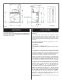
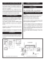
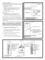
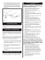
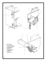
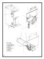
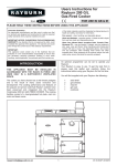
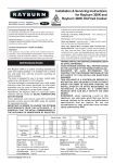
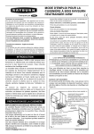
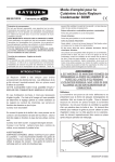
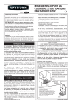
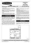
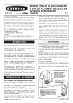
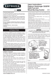
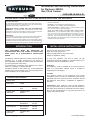
Installation and Servicing Instructions
for Rayburn 200G/L
Gas Fired Cooker
FOR USE IN GB & IE
PLEASE READ THESE INSTRUCTIONS BEFORE INSTALLING THE APPLIANCE
Consumer Protection
As responsible manufacturers we take care to make sure that our
products are designed and constructed to meet the required safety
standards when properly installed and used.
below for information.
Firebricks – when handling use disposable gloves.
Fire cement – when handling use disposable gloves.
Glues and sealants – exercise caution – if these are still in liquid
form use face mask and disposable gloves.
IMPORTANT NOTICE: PLEASE READ THE ACCOMPANYING
WARRANTY. Any alteration that is not approved by AGA, could
invalidate the approval of the appliance, the warranty and could also
infringe the current issue of the statutory requirements.
Glass Yarn, Mineral Wool, Insulation Pads, Ceramic Fibre,
Kerosene Oil – may be harmful if inhaled, may be irritating to skin,
eyes, nose and throat. When handling avoid inhaling and contact
with skin or eyes. Use disposable gloves, face masks and eye
protection. After handling wash hands and other exposed parts.
When disposing of the product reduce dust with water spray, ensure
that parts are securely wrapped.
IMPORTANT:
This appliance could contain any of the materials that are indicated
below. It is the Users/Installers responsibility to ensure that the
necessary personal protective clothing is worn when handling, where
applicable, the pertinent parts that contain any of the listed materials
that could be interpreted as being injurious to health and safety, see
INTRODUCTION
INSTALLATION INSTRUCTIONS
THIS APPLIANCE MUST BE INSTALLED IN
ACCORDANCE WITH THE RULES IN FORCE AND
USED ONLY IN A SUFFICIENTLY VENTILATED
SPACE.
Gas connection 15mm O.D. copper.
Open flue outlet 100mm min.
Electric Supply 50Hz 3 amp fused 230V.
Weight of Appliance 275Kg.
The Rayburn 200G/L Gas-Fired Cooker provides cooking
facilities only. A single atmospheric gas burner is
thermostatically controlled at cooking rates, and operates
at a low bypass rate when idling.
The exhaust flue connection of the appliance is in Open
Flue form, operating on natural draught.
Facilities included on the cooker are, a heat graduated
hotplate, main oven and lower oven. A timing programmer
is also available, as an optional extra.
In your own interests, and that of safety, all gas
appliances should be installed by competent persons, in
accordance with the regulations in force.
Appliance
The appliance must be installed on a solid level floor or
base of incombustible material which is capable of
supporting the total weight.
Location
The location chosen for the appliance must permit
installation and the provision of a satisfactory flue and an
adequate space for servicing and air circulation around
the appliance. See Section - Installation of Appliance General.
Technical Specification
Natural Gas
Heat Input
5.6kW
Pressure
G20
G25
Injector Size
Pilot Size
1.82 Bray 460
38/36A
REMEMBER, when replacing a part on this appliance,
use only spare parts that you can be assured conform to
the safety and performance specification that we require.
Do not use reconditioned or copy parts that have not
clearly authorised by AGA.
20mbar
25mbar
LP
Heat Input
6.3kW
Nominal Rate
G31 Propane
G30 Butane
489 g/h
497 g/h
Inlet Pressure
G31 Propane
G30 Butane
37mbar
28mbar
Injector Size
Pilot Size
1.27 Bray 220
4209
[email protected]
1
01/10 EINS 510974
Fig. 1
GAS SUPPLY
FLUE SYSTEM
Installation Gas pipes
Do not use pipes of a smaller size than the appliance gas
connection. The complete installation must be tested for
soundness and purged.
The following notes are intended to give general
guidance:The cross-sectional area of the flue serving the cooker
must not be less than the area of the flue outlet of the
cooker, and at least 3m high from the floor level. If flue
pipe is to be used it must not be less than 100mm internal
diameter.
Flue pipes and fittings should be constructed from one of
the following materials:
(a) Cement
(b) Aluminium or stainless steel
(c) Cast iron or mild steel acid resistant vitreous enamel
lined
If a chimney is to be used, it preferably should be one that
is composed of, or lined with, a non-porous acid resistant
material. (Chimneys lined with salt glazed earthenware
pipes are acceptable). A flue pipe constructed in (a) to (c),
should form the initial connection to lined chimneys.
Where a chimney is to be used which is not composed of
or lined with a non-porous acid resistant material it should
be lined with a stainless steel flexible flue liner. The
internal diameter of the liner must be not less than 100mm
and the number of joints must be kept to a minimum. If the
flue liner is not to be connected directly to the appliance
draught diverter, a flue pipe which is manufactured from
one of the materials in (a) to (c) should form the
connection between the draught diverter and flue liner.
Before connecting the appliance to or inserting a liner
into, a flue that has been previously used the flue MUST
be thoroughly swept clean of any soot and loose material.
If a register plate, restrictor plate, damper etc. is fitted in
the flue it MUST be removed before connecting the
appliance to, or inserting a liner into the flue.
The flue should terminate in accordance with the relevant
standards in force.
2
EFFECT OF AN EXTRACTION FAN
COMBUSTION AIR SUPPLY
If there is any type of extract fan fitted in the same room
as an appliance, there is a possibility that if adequate air
inlet area from outside is not provided, spillage of the
products from the appliance flue could occur when the
extract fan is in operation.
Where such installations occur, a spillage test must be
carried out as follows:- By holding a smoke match so that
the flame is approximately 3mm up inside the lower edge
of the draught diverter. Spillage is indicated by the smoke
being displaced outwards from the draught diverter.
Any necessary remedial action must then be taken.
13m3/h of fresh air is required.
VENTILATION
60m3/h of fresh air is required.
THIS APPLIANCE MUST BE INSTALLED
ACCORDANCE WITH REGULATIONS IN FORCE.
INSTALLATION OF APPLIANCE
General
The appliance is floor-mounted and must have the
following minimum clearances for servicing/installation:Between wall and LH side of appliance 150mm
Between wall and RH side of appliance 25mm
Above the raised insulating cover handle 60mm
ELECTRICAL SUPPLY
Wiring external to the appliance must be installed in
accordance with the current Wiring Regulations and any
local regulations which apply. The appliance is supplied
for 230V ~ 50Hz and fuse rating of 3A.
The method of connection to the mains electricity supply
must facilitate complete electrical isolation of the
appliance, preferably by the use of an unswitched
shuttered socket outlet in conjunction with a fused threepin plug.
Where the cooker is to stand in a recess or against a wall
which is to be tiled, in no circumstances should the
tiles overlap the cooker top plate.
In addition, adequate clearance must be available at the
front of the appliance to enable it to be operated and
serviced. Flue piping and fittings must not be closer than
25mm to combustible materials and where passing
through a combustible partition such as a ceiling or roof,
must be enclosed in non-combustible sleeve providing an
air space of at least 25mm.
Spaces around flue pipes passing through walls or floors
should be sealed against the passage of smoke and
flame.
Alternatively, a fused double-pole switch having contact
separation of at least 3mm in both poles serving only the
appliance may be used.
The point of connection to the mains should be readily
accessible and adjacent to the appliance. For wiring
instructions See Fig. 2.
CONTROLS
An optional external electrical programmer is available,
which will provide a timing feature to switch the main oven
to the desired temperature setting as and when required.
See Fig. 3.
COOKER STAT.
E P PROGRAMMER
MOUNTING PANEL
CDSD
MAINS INPUT
(FUSED 3 AMP)
LINK
COOKER STAT.
SOLENOID
MAINS INPUT
(FUSED 3 AMP)
CDSD
KEY
SOLENOID
Fig. 2
IN
Wiring diagram without programmer
Fig. 3
3
G/Y BL BR -
GREEN/YELLOW
BLUE
BROWN
Wiring diagram with programmer
Preliminary Installation
The appliance is delivered assembled with the exception
of the following items which are supplied separately
packed and require assembly.
1. Draught Diverter Assembly
See Fig. 4.
2. Appliance Rear Distance Bracket (For use when
appliance is Bracket installed 25mm away from a
rear wall of combustible material). See Fig. 5.
3. Insulating Covers.
4. Handrail Brackets and Handrail
Site Location
1. Remove the appliance assembly from its transit
wooden pallet by the temporary location of a
sloping ramp board between the pallet and the floor.
With the appliance on the floor carefully lift the appliance
(taking care not to damage the enamelled/painted
components of the floor covering in the room) and insert
suitable rollers beneath the base plate to aid positioning
of the appliance.
When in position remove rollers and continue assembly.
Fig. 4
NOTE: IF THE REAR WALL IS OF COMBUSTIBLE
MATERIAL, THERE MUST BE AN AIR GAP OF 25mm,
BETWEEN THE WALL AND REAR OF APPLIANCE.
FIT REAR DISTANCE BRACKET AS SHOWN IN FIG. 5.
2. Assemble and locate the flue draught diverter
assembly on the top plate. See Fig. 4.
3. Fit a 600mm minimum vertical height of flue pipe
into the draught diverter flue socket, sealing joint
with fire cement. See Fig. 6.
4. The flexible liner joint and the entire flexible liner
should be in the confines of the flue.
5. Insulating covers are placed in position and
secured in position (see instruction sheet provided)
Fig. 5
Fig. 6
4
6. The handrail brackets are held on the front ends
of the cooker top-plate casting. Remove the travel
nuts and replace with handrail brackets ensuring
the fibre protecting washers are in position. Insert
the handrail with fitted endcaps into the brackets,
positioning them correctly, tighten the locating bolts.
(See Fig. 6A).
LIGHTING THE BURNER See Fig. 7
IMPORTANT: IF THE PILOT IS EXTINGUISHED FOR
ANY REASON, ALWAYS WAIT AT LEAST 3 MINUTES
BEFORE ATTEMPTING TO RELIGHT.
1. Switch OFF the electricity supply at the wall
socket and ensure the optional programmer if
fitted is switched to the OFF position.
2. Ensure that the thermostat knob D is at the O
position Fig. 7.
3. Open the outer burner door A.
4. Turn ON the service cock E (below cooker burner
control valve) so that the screwdriver slot is in line
with pipework.
5. Turn the control knob B to the ignition symbol and
depress it fully.
6. Keeping control knob B depressed fully
simultaneously press Piezo Spark Generator C
repeatedly until the pilot flame lights. This is
visible through the sight glass F (Fig. 7) (A few
seconds must be allowed for the gas to reach the
pilot burner).
7. Continue to hold down Control Knob B for at least
15 seconds after the pilot flame has lit, then
release the knob slowly. The pilot flame will
remain if its presence has been detected by the
flame sensor unit.
8. Check with leak detection fluid for gas soundness
at the joint of the pilot supply pipe with the control
valve.
9. Check that the pilot flame is enveloping the pilot
thermocouple.
10. With the thermostat knob D still at its setting O.
TURN the Control Knob B to the large main flame
symbol.
11. Turn thermostat knob D to No. 9, turn ON the
electricity supply, and the programmer if fitted
requires setting to continuous.
12. Check that the main burner flame has lit.
13. Check that the pressure is correct.
14. Check that the gas pressure is maintained and
unaffected when other gas appliances are used.
Fig. 6A
GAS INSTALLATION
Connect the gas supply to the pre-formed 15mm O.D.
copper pipe from the integral union gas service cock on
the appliance.
ELECTRICAL CONNECTIONS
A 230V ~ 50Hz electrical is required near to the appliance.
The appliance is supplied with a 0.75mm2 (24 x 0.2mm) 3 core PVC x 2 metres long 85ºC rated replaceable power
supply cable connected as described under Electrical
Supply.
A label attached to the end of the flexible cable gives
details of the cable core colour coding and their function
which should be adhered to. When connecting to a 3 pin
plug, observe the following recommendations:-
NOTE:- THIS APPLIANCE IS FITTED WITH A
COMBUSTION DISCHARGE SAFETY DEVICE WHICH
WILL SWITCH OFF THE MAIN BURNER IN ADVERSE
FLUE CONDITIONS. BEFORE TURNING ON MAIN
BURNER ENSURE THAT THE MANUAL RESET
BUTTON IS DEPRESSED. (FIG. 7).
1. The wire which is coloured green-and-yellow must be
connected to the terminal in the plug which is marked
with the letter E or by the earth symbol or coloured
green or green and yellow.
2. The wire which is coloured blue must be connected to
the terminal which is marked with the letter N or
coloured black.
15. Check that there is no spillage of combustion
products from the appliance down-draught
diverter by carrying out a spillage test i.e. By
holding a smoke match so that the flame is
approximately 3mm up inside the lower edge of
the draught diverter. Spillage is indicated by the
smoke being displaced outward from the draught
diverter. Inspect flame pattern and appearance of
burner to establish that there is adequate air for
combustion.
16. Turn the control knob D to O and remove the
pressure gauge from the burner test nipple, then
replace the sealing screw.
17. Close outer burner door.
3. The wire which is coloured brown must be connected
to the terminal which is marked with the letter L or
coloured red.
COMMISSIONING AND TESTING
The whole gas installation, must be inspected and tested
for soundness, and purged up to the appliance gas cock.
5
Fig. 7
6
HOW TO OPERATE
COOKER CONTROL
METHOD OF APPLIANCE
CONTROL
Overnight and when not required for cooking, leave
thermostat knob D at LOW position. To increase the
temperature of the oven or hotplate, turn the thermostat
knob D to required temperature setting. See separate
programmer operating instructions to set the programmer
if fitted.
The cooker burner provides heat for two ovens and
hotplate. A main gas service cock is incorporated below
the cooker burner control valve.
Operation
The burner K has a permanent pilot light H protected by a
flame supervision valve. Turning ON the main gas service
cock E to allow gas to the gas control valve and turning
and pressing control knob B to
allow gas to pass to
the pilot light H which must be lit by means of the Piezo
(knob C).
TO TURN OFF COOKER BURNER
Press and turn control knob B clockwise to off (O symbol)
whereupon the main cooker burner and the pilot burner
will extinguish.
When the pilot heats the thermocouple probe J correctly,
gas is allowed through the flame failure device.
ADVISE USER ABOUT THE FOLLOWING ITEMS ON
COMPLETION OF INSTALLATION.
Depressing the control knob B and turning to
allows
the gas to the main burner K which crosslights from the
pilot burner.
(a) For continued efficient and safe operation of the
appliance, it is important that adequate servicing is
carried out annually.
LOW is the minimum (and idling) gas rate and turning the
Thermostat knob to D to a higher setting selects the
temperature of the ovens required for cooking.
(b) Hand these Instructions and the Operating
Instructions to the User and demonstrate the correct
operation of the appliance and system controls, See
notes under heading ‘Methods of Appliance Control’.
When not in use, reset the knob D to LOW.
Note: The cooker is designed to be alight continuously,
with the Thermostat at LOW during times of low cooking
load or idling conditions, and the thermostat set to give
the appropriate oven conditions when cooking - see the
Rayburn Cook Book for recipes.
7
Servicing Instructions
To Clean Heat Exchanger and Flueways
a. Replace the main and pilot burner assembly as
previously described.
b. Place a layer of paper on combustion chamber
baseplate.
c. Examine insulation panels for any sign of
deterioration, replace if necessary.
d. Remove layer of paper with fallen debris.
e. Check that oven top is free of deposit and brush
in between ribs on hotplate underside.
f. Examine soft rope seal located on the underside of
hotplate baffle plate, Replace if worn or frayed.
g. Examine soft rope seal located around hotplate
aperture in top plate. Replace if frayed or damaged.
h. Re-fit the main and pilot burner assembly in
reverse order of assembly. Test all disconnected
joints for gas soundness.
i. Replace hotplate ensuring that the underside ribs
lie over the combustion chamber.
j. Turn ON appliance service cock on outside of
appliance. Light pilot and turn oven control knob
to confirm the burner lights satisfactorily in
accordance with lighting instructions.
ANNUAL SERVICING
It is important that servicing is carried out by a
competent service engineer, and it is recommended
that a contract be made with a registered installer.
The householder should be advised to turn OFF the
cooker control knob B the night before, the day of the
service, so that the appliance will be cooled down by the
following morning, in readiness for servicing. Before
commencing any servicing, turn OFF the gas supply at
the appliance gas service cock (below cooker burner
control valve).
WARNING: DISCONNECT FROM ELECTRICITY
SUPPLY
AND
REMOVE
PLUG
BEFORE
COMMENCING SERVICING.
SERVICE SCHEDULE
Oven Door Fit - Both doors must be checked and
adjusted if necessary to ensure the alignment with the
door catch is correct, the keep is secure and the oven is
sealed when the door is closed.
REPLACEMENT OF PARTS
To Obtain Servicing Access - Fig. 1.
Only to be carried out by a competent Service
Engineer.
To obtain servicing access to main gas burner, gas control
and heat exchanger, proceed as follows:
a. Lift out the hotplate.
b. Open the outer burner door A and lift it off.
c. Disconnect the main burner inlet union
connection below valve.
d. Loosen the two tap fixing screws and remove the
two lower fixing screws on the burner front plate.
e. Lift up the burner front plate and draw carefully
forward.
f. Lift up the burner front plate and draw carefully
forward.
1. Oven Temperature Indicator
a. Open main oven door and remove from cooker.
Place enamelled side on a cloth to protect it, and
remove four screws securing inner lining panel to
outer door.
b. Remove inner lining panel and slagwool insulation.
c. Unscrew two hexagon nuts securing indicator to
outer door and remove indicator.
d. Fit replacement indicator in reverse order of
dismantling.
e. Seal indicator to door with heat resistant string
and seal with fireclay.
f. Reassemble as c, to a, above.
To Service Main Burner
Gently brush away any deposit on burner and examine
gas ports. Remove any lint or fluff from injector and
venturi entrance, and check pilot burner assembly for
damage, and probe bracket for correct alignment.
2. Thermocouple
a. Remove burner assembly as detailed in Servicing
Schedule.
b. Remove thermocouple from gas valve.
c. Remove thermocouple from pilot burner.
d. Replace with new thermocouple assembling in
reverse order.
e. Reassemble burner assembly into cooker.
DO NOT USE WIRE TO CLEAN INJECTOR ORIFICE.
To Service Pilot Burner
Remove pilot burner as instructed in ‘Replacement of
Parts’ in Section 5.
Remove pilot injector and check to see if it is free of
deposit with a tooth brush bristle or similar if necessary.
3. HT Spark Lead
a. Remove burner assembly as detailed in Servicing
Schedule.
b. Remove HT Spark Lead from Piezo Spark Generator.
c. Remove HT Spark Lead from Spark Electrode.
d. Replace with new HT spark lead, reassembling in
reverse order.
e. Reassemble burner assemblies into cooker.
DO NOT USE WIRE TO CLEAN INJECTOR ORIFICE.
Examine probe end of flame failure device and replace
flame failure probe if probe end is badly pitted, corroded
or malfunctioning.
8
4. Spark Electrode
a. Remove burner assembly as detailed in Servicing
Schedule.
b. Remove HT spark lead from spark electrode.
c. Remove spark electrode.
d. Replace with new spark electrode taking care not
to put any strain on the ceramic body replace
screw to secure position.
e. Reconnect the HT spark lead.
f. Reassemble burner assembly into cooker.
behind the thermostat.
n. Now reverse the order of the above to
reassemble (h-b).
7. Gas Valve
a. Remove burner assembly as detailed in Servicing
Schedule.
b. Remove thermocouple from S.I.T. valve.
c. Remove HT spark lead from Piezo.
d. Remove pilot feed pipe from gas valve.
e. Remove main burner feed pipe from outlet of
solenoid.
f. Unscrew the two fixing bolts holding gas valve to
its mounting plate.
g. Remove Piezo complete with its mounting
bracket from gas valve.
h. Remove inlet gas assembly complete.
i. Remove solenoid valve from gas valve.
j. Fit new gas valve reassembling in reverse order.
5. Pilot Assembly
a. Remove burner assembly as detailed in Servicing
Schedule.
b. Remove HT spark lead from spark electrode.
c. Remove thermocouple from pilot burner.
d. Slacken pilot feed pipe nut.
e. Remove the pilot burner fixing screw.
f. Release the pilot feed pipe and unscrew the pilot
burner injector.
g. Examine/clean or renew the injector before
replacing it in the new pilot burner.
h. Re-assemble the injector into the pilot burner
assembly.
i. Enter the pilot feed pipe nut into the pilot burner
and turn by hand a few times.
j. Replace the pilot burner on to its support bracket
and tighten the screws.
k. Tighten the pilot feed pipe nut fully with a spanner.
l. Replace thermocouple.
m. Replace spark electrode taking care as detailed
in (4) above.
n. Replace HT spark lead.
o. Reassemble burner assembly into cooker.
8. Solenoid
a. Remove burner assembly as detailed in
‘Servicing’ above.
b. Remove thermocouple from S.I.T. valve.
c. Remove HT spark lead from Piezo.
d. Remove pilot feed pipe from gas valve.
e. Remove main burner feed pipe from outlet of
solenoid.
f. Unscrew the two fixing bolts holding gas valve to
its mounting plate.
g. Remove Piezo complete with its mounting
bracket from gas valve.
h. Remove inlet gas assembly complete.
i. Remove solenoid valve from gas valve.
j. Fit new solenoid reassembling in reverse order.
6. Thermostat
a. Ensure that the cooker is ISOLATED FROM
THE POWER SUPPLY.
b. Remove thermostat control knob by grasping
firmly and pulling off the spindle.
c. Remove the four fixing screws which secure the
thermostat mounting plate to the cooker side plate.
d. Remove the earth lead and note position of
electrical connection and remove.
e. Unscrew the locknut and washer securing the
thermostat.
f. Open top oven door.
g. Slacken the rear screw securing the LH side
panel casting in the oven.
h. Remove the front screw from the LH side panel,
which allows it to swing out and give access to
the thermostat phial mounting brackets.
i. Pull the capillary out of the tube along the front of
the cooker sufficiently to enable the phial to be
removed from its clips (push the phial towards the
rear of the oven to release it from the front bracket).
j. The thermostat can now be removed.
k. Straighten an equivalent length of capillary on the
new thermostat taking care when doing so not to
kink it.
l. Feed the capillary back through the front tube into
the oven and relocate the capillary in the support
brackets.
m. Draw the spare capillary back towards the left of
the cooker and carefully coil the spare capillary
9.
a.
b.
c.
d.
Combustion Discharge Safety Device
Disconnect from mains electricity.
Remove thermostat knob.
Remove screw securing control panel.
Ease control panel away from cooker and allow panel
to hang on wires.
e. Remove spindle locknut and electric leads from
CDSD.
f. Remove CDSD phial from spring clip in downdraught
diverter hood. Fig. 4.
g. Withdraw CDSD and fit replacement in reverse order.
LEAVE SERVICING INSTRUCTIONS WITH THE USER
FOR FUTURE USE.
9
Fig. 8
10
11
For further advice or information contact
your local distributor/stockist
With AGA’s policy of continuous product
improvement, the Company reserves the right to
change specifications and make modifications to
the appliance described at any time.
Manufactured by
AGA
Station Road
Ketley Telford
Shropshire TF1 5AQ
England
www.rayburn-web.co.uk
www.agacookshop.co.uk
www.agalinks.com
12