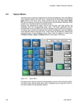
1
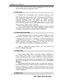
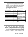
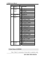
LedControlCard.com Focus On led card and led video processor
LVS5066
LED HD Seamless Switcher
USER’S MANUAL
www.ledcontrolcard.com
led control website.
LVS5066 User’s Manual
TABLE OF CONTENTS
I. Safety precautions
3
II. Connections of hardware
1. Rear view
2. Port description
3. Connection diagram
4
5
6
III. Frontal panel operations
1. Diagram of frontal panel
2. Button instructions (operation mode)
7
7
IV. Setup
1. Enter setup
2. Select language
3. Output image setup
4. Brightness / color
5. PIP and Text_Overlay setup
6. Exit setup
7. Factory district setup
13
13
14
15
15
17
18
V. Specifications
19
VI.Notes to model……………………………………………………………….20
---------------------------------------------------------------------------------------------------
LED VIDEO PROCESSOR
2
LVS5066 User’s Manual
I.
Safety Precautions
Danger!
There is high voltage in the processor, to prevent any unexpected
hazard, unless you are maintenance, please do not open the cover of the
device.
Warning!
1. This device shall not encounter water sprinkle or splash, please do not
place anything containing water on this device.
2. To prevent fire, keep this device far from any fire source.
3. If this device gives out any strange noise, smoke or smell, please
immediately unplug the power cord from receptacle, and contact local
dealer.
4. Please do not plug or unplug DVI signal cable when the device
on power.
Caution!
1. Please thoroughly read this manual before using this device, and keep
it well for future reference.
2. In the event of lighting or when you are not going to use the device for
a long time, please pull the power plug out of receptacle.
3. Nobody other than professional technicians can operate the device,
unless they have been appropriately trained or under guidance of
technicians.
4. To prevent equipment damage or electric shock, please don’t fill in
anything in the vent of the device.
5. Do not place the device near any water source or anywhere damp.
6. Do not place the device near any radiator or anywhere under high
temperature.
7. To prevent rupture or damage of power cords, please handle and keep
them properly.
8. Please immediately unplug power cord and have the device repaired,
when
1) Liquid splashes to the device.
2) The device is dropped down or cabinet is damaged.
3) Obvious malpractice is found or performance degrades.
---------------------------------------------------------------------------------------------------
LED VIDEO PROCESSOR
3
LVS5066 User’s Manual
II. Connections of hardware
1. Rear view
Figure 1
---------------------------------------------------------------------------------------------------
LED VIDEO PROCESSOR
4
LVS5066 User’s Manual
2. Port description
1) Video Input
LVS5066’s signal input employs plug & play design, the type and
number of input image signals are configurable based on user’s
demand. Each image capture card is arranged with one channel (as
shown in figure below). Now HD Seamless Switcher is configured with
4 or 6 pieces of image capture cards.
Each image capture card of LVS5066 supports the following video
signal inputs:
Port name
Description
1-channel PAL/NTSC composite video input
V1
1-channel computer analog signal input
VGA
1-channel HDMI digital HD signal input
DVI /HDMI
1-channel digital video signal input (HD /SD)
SDI/HDSDI (IN)
2) Main output ports(DVI)
2 same DVI digital video outputs. They can be connected with
external LED transmission card or LED transmission box.
3) Pre-view monitor output port
With this port, the images you currently selected in 6 channels can
be displayed in one monitor, so that user could perform real-time
monitoring over the images of each channel and switch the video
timely and accurately.
Terminal
Description
Analog RGB output. It can be connected
VGA OUT
to a local display and used as monitor.
DVI digital video output. It can be
DVI OUT
connected to a local display and used as
monitor.
4) Signals of other ports
25pin D-SUB, connected with control panel.
---------------------------------------------------------------------------------------------------
LED VIDEO PROCESSOR
5
LVS5066 User’s Manual
3. Connection diagram
---------------------------------------------------------------------------------------------------
LED VIDEO PROCESSOR
6
LVS5066 User’s Manual
III. Frontal panel operations
1. Diagram of control panel
Figure 2
2. Button instructions (operation mode):
There are 65 buttons on the control panel of LVS5066, of which 45
buttons on the left are used to switch input signals. The 20 buttons on
the right are function and setting buttons, used for mode switching or
settings.
1) Select input video source
LVS5066 has 6 channels, their buttons are Ch1, Ch2, ……Ch6
respectively. Each channel is furnished with 6 operation buttons. The
table below lists the functions of these buttons:
Port name
Description
Input signal via V1, V2 BNC port
V1~V2
Computer analog signal input
VGA
HDMI digital HD signal input
HDMI
Computer digital signal input
DVI
Digital video signal input (HDSDI)
SDI
Turn on/off PIP in each channel. When the
PIP(INx)
indicator lights up, the function is on.
Turn on/off Text or POP in each channel. When
TEXT/POP
the indicator lights up, the function is on.
---------------------------------------------------------------------------------------------------
LED VIDEO PROCESSOR
7
LVS5066 User’s Manual
Notes: LVS5066 adopts 2-level switching architecture. Level 1
switching is input pre-selection switching, namely the switching
among 4 signals in a single channel; Users can proceed to level 2
switching namely switching between channels until all inputs
pre-selection of each are completed. which is used to realize a series
special switching effects such as seamless switching, fading-in/out,
WIPE or used to select PIPs. Seamless switching can be realized
among signals in channels.
2) Select output brightness
Button names
BRT BRT +
Description
Decrease output image brightness of
LVS5066, the lowest brightness is 0.
Increase output image brightness of LVS5066,
the highest brightness is 64.
LVS5066 supports 32 levels Brightness, “0” represents the
lowest brightness, and 64 represents the highest brightness. To
ensure full gray level of output image, normally the output
brightness is set as 64!
3) VGA input auto adjustment (Auto)
With this button, LVS5066 can automatically adjust the
sampling parameters of VGA input signals to make VGA picture
clear and complete. Operating procedures: when the main output is
the VGA input signal, first press VGA input selection button of the
channel, for example, VGA button of Ch3. Press “Auto” button
before the message “Source Ch2.=VGA” disappears in the screen.
In general, this operation is made only when new VGA signal
source is to be connected in. The time spent in auto adjustment
may vary with the conditions of signal source, but it is usually
shorter than 1 minute. Sometimes user need repetitively do such
adjustment till VGA picture looks clean, complete and stable.
4) Information display (Info)
This button can be operated to display the Current settings of
LVS5066.
press Info button to display current settings and information of
LVS5066. There are total 29 entries of information. Press “Info”
--------------------------------------------------------------------------------------------------- 8
LED VIDEO PROCESSOR
LVS5066 User’s Manual
button again before the information disappears in LCD, the next
entry of information will appear in LCD.
5) CUT mode
LVS5066 will automatically enter seamless switching mode
after startup. Now the indicator is ON. If the moment LVS5066 is in
other switching modes, you can press CUT button to enter
seamless switching mode. The system will realize seamless
switching between the six channels, i.e.: Ch1, Ch2…Ch6. The
picture will change fluently and stably without flicker, tremble, stasis,
delay, tearing or black screen occurring.
PS: the switching between different signals of current channel
will lead to black screen. The above switching effects are only
realizable in the switching between different channels.
6) Fade-in/Fade-out(Fade)
Press Fade button while in operation mode, LVS5066 will enter
Fade-in/Fade-out(Fade) mode, the moment the switching time
“Fading Time= N Seconds” will appear in LCD (N represents the
number of seconds, e.g.: 1, 2, 3…). The moment, the system can
realize seamless switching between the 6 channels, i.e.: Ch1,
Ch2…Ch6 without any tremble or interference occurring.
While in Fade-in/Fade-out(Fade) mode, user can press Fade
button to change fading time.
7) Fader mode
Press Fader button while in operation mode, LVS5066 will
enter Fader mode. Now you can operate T-Fader manually to
control the fading process, or stop it halfway to make new picture
and old one overlay each other in transparent mode. LCD displays
the ratio of the signals in the recent two channels, e.g.: “CH3=100%
CH5=0%”.
Operating procedures: press a button to select the channel to
be switched, then push T-Fader forward or backward, the image will
change in fading-in/out mode. If no signal is selected, when T-Fader
is pushed, the screen will return to the picture of the channel most
recently displayed.
8) WIPE mode
---------------------------------------------------------------------------------------------------
LED VIDEO PROCESSOR
9
LVS5066 User’s Manual
LVS5066 supports 4 WIPE modes. Press WIPE1, WIPE2,
WIPE3 while in operation mode, LVS5066 will enter corresponding
wipe mode, the moment corresponding mode will appear in LCD
(e.g.: “Switch Mode= Wipe: L → R”). Table below lists the
descriptions of each switching mode and their respective operation
buttons:
Switching
direction
L→R
L←R
L←M→R
RECT
Description of mode
Buttons
Wipe from the left toward the right
Wipe from the right toward the left
WIPE1
(as
described
in note)
Wipe from the centre toward both WIPE2
sides
If it is a square, wipe from the WIPE3
centre perimeter
Note: Both L→R and L←R modes (as described in above
table) are operated using WIPE1 button. User can press this button
to switch the modes.
9) PIP / POP
LVS5066 has PIP function, that is to say, it can add a zipped
picture (PIP) to current picture (background). The PIP can be
switched between the 6 channels including the background. User
can preset the size of 4 PIPs switch between them. The switching
between PIPs is made in Fade-in/Fade-out(MIX) mode.
Operating procedures:
Enter PIP display mode: press PIP button while in any mode,
LVS5066 will enter PIP mode, in the meantime, the information on
the background channel and the position and channel of PIP to be
added will appear in LCD, e.g.: “Background=CH2,PIP_3=CH5”.
Select PIP: while in PIP mode, select 1 channel from the 6
channels, the picture in this channel will be set as PIP.
Change position of PIP window: press PIP button while in
PIP mode, the position of the PIP in LCD will become vacant, e.g.:
“Background=CH2,PIP_3=CH”. Press PIP again, PIP will move to
another position. When PIP arrives at the position you selected
(e.g.: PIP_4), reselect PIP channel (e.g.: CH1), the PIP will appear
in the new position after a Fade-in/Fade-out action (the moment
--------------------------------------------------------------------------------------------------- 10
LED VIDEO PROCESSOR
LVS5066 User’s Manual
“Background=CH2,PIP_4=CH1” will appear in LCD).
Change the background: you must first switch LVS5066 into
CUT mode, then select a channel you desire as background, and
press PIP to enter PIP mode, and next, reselect PIP.
10) Text overlay mode (Text)
LVS5066 provides text overlay function: first switch into CUT
mode, then select a channel you desire as background, then press
Text to enter text overlay mode, and next, select the channel of the
text.
Text overlay signals: to ensure good text displaying effect,
please select digital signals such as DVI/HDMI signals. The
background must be full white or black (the switcher is to be
switched into corresponding mode). The text is to be made in other
colors. See the figure below (the text is made by Powerpoint)
Main picture
Text
Text overlay effect
---------------------------------------------------------------------------------------------------
LED VIDEO PROCESSOR
11
LVS5066 User’s Manual
11) Preview multi pictures display model( Preview ?, OK)
LVS5066 not only can show the current chosen input signal of the
six channels, also its preview output can support 7 kinds multi pictures
display. These displays are from CH1-CH4 which can be realized by
connecting DVI to CH5 or CH6, then to LED screen by pressing cut
button. The operation method is as follow:
Press “Preview?” button in succession to cut display modes.
Then press “Preview ok” to make the chosen mode become effective.
Multi pictures modes
PM60:2X3=6 Pictures
PM40:2X2=LU+RU+LD+RD
showing
contents
CH1~CH6
CH1~CH4
PM34:3X1= U+M+D
CH1~CH3
PM33:1X3=L+RU+RD CH3=L
PM32:1X3= L+RU+RD CH2=L
PM31:1X3= L+RU+RD CH1=L
CH1~CH3
CH1~CH3
CH1~CH3
PM30:1X3= L+M+R
CH1~CH3
PM21:2X1= U+D
CH1、CH2
PM20:2X1= L+R
CH1、CH2
showing instruction
6 picture preview
2x2 mode four
pictures
display of 4channels
three pictures display of up,
middle and down
Three pictures display of one
main picture and two pictures
on the up and down of the right
side.
Three pictures display of left,
middle and right.
Two pictures display of up and
down.
Two pictures display of left and
right.
IV. Setup
The following setup must be made by relevant qualified
technicians. For ordinary users, unless they have received adequate
relevant training, they shall not attempt the following setup
operations!
There are 33 items in 5 categories available for you to set in LVS5066.
Technicians can set these items as necessary, for details see the table
below:
---------------------------------------------------------------------------------------------------
LED VIDEO PROCESSOR
12
LVS5066 User’s Manual
Category
1
Select
language
2
Output
Image
Setup
3
4
5
Brightness /
Color
PIP/POP
setup
Factory
district
Setup
Items
1
Language
2
3
4
5
6
7
8
9
10
11
12
13
14
15
16
17
18
19
20
21
22
23
24
25
26
27
28
29
30
31
32
33
Hori_Start
Hori_Width
Vert_Start
Vert_Height
Out_Format
Brightness
Color
Out_PIP1_H_Start
Out_PIP1_H_ Width
Out_PIP1_V_Start
Out_PIP1_V_ Heigh
Out_PIP2_H_Start
Out_PIP2_H_ Width
Out_PIP2_V_Start
Out_PIP2_V_ Heigh
Out_PIP3_H_Start
Out_PIP3_H_ Width
Out_PIP3_V_Start
Out_PIP3_V_ Heigh
Out_PIP4_H_Start
Out_PIP4_H_ Width
Out_PIP4_V_Start
Out_PIP4_V_ Heigh
Inx_PIP_H_Start
Inx_PIP _H_ Width
Inx_PIP_V_Start
Inx_PIP_V_ Heigh
Text_Overlay
PIP_Frame
Init
Auto ADC
Bias
1. Enter Setup of LVS5066
Press “Setup” for consecutive 8 times while in operation mode,
---------------------------------------------------------------------------------------------------
LED VIDEO PROCESSOR
13
LVS5066 User’s Manual
“Password: 8 Enter Setup …” will appear in LCD, LVS5066 will enter
the No.1 setup item.
After LVS5066 enters the setup mode, the 7 buttons on frontal
panel will have the functions as defined in table below:
Name
Step
↑
↓
←
→
Enter
Setup
Functions
Select step value 1 or 10
Move to last item
Move to next item
Decrease value or select last value
Increase value or select next value
Save the adjustment or selected values
Enter or exit setting mode
After LVS5066 enters setup mode, the relevant setup information
will be displayed in LCD as per the layout shown in the figure below:
2
: Hori_Start
?200 Stp=10
Figure 3
1
2
3
4
5
As shown in above figure, LCD consists of five sectors:
Sector Description
1
The No. of current setting item
2
?: ask you whether to save the adjustment; !: The
adjustment already be saved and takes effect.
3
Newly adjusted value
4
Step value
5
Name of current setting item
2. Select language
Item 1: “Language 语言 ”
After entering setup mode, LVS5066 will enter the first settup item
“Language 语言 ”. LVS5066 supports Chinese and English display,
press “←” or “→” to select either of them, then press “Enter” to save
it and make it valid.
---------------------------------------------------------------------------------------------------
LED VIDEO PROCESSOR
14
LVS5066 User’s Manual
3. Output image setup
LVS5066 outputs images from DVI OUT1 and DVI OUT2. There are 3
output formats as listed in the table below. User can enter the No.6 setup
item “Out Format” to select one of them.
Format
1024×768_60
1280×1024_60
1920×1080_60
1
2
4
Item 6: “Out Format”
Press “←” or “→” key to select 1 output format listed under this
option, then press “Enter” to save it.
If you select “1024×768_60”, the output resolution of LVS5066 will
be 1024×768; the vertical refresh rate is 60Hz.
However, the resolution of LED screen is not exactly 1024×768
pixels. When the resolution of LED screen is less than 1024×768
pixels, we can set LVS5066 to output the images exactly fitting the
resolution of LED screen, so that the LED could display a full frame of
image. See the schematic diagram below:
(0,0)
Hor_Str
Vert_Str
Hor_Width
LVS5066 Out Image Area
LED Dispaly Screen
768
Vert_Height
LVS5066 Out Format = 1024×768
1024
Figure 4
---------------------------------------------------------------------------------------------------
LED VIDEO PROCESSOR
15
LVS5066 User’s Manual
As above figure shows: the size and location of LVS5066 output
images are defined by 4 groups of parameters, which correspond to
four setting items respectively, for details of their relationship see Table
5 below:
No. of setup item
2
3
4
5
Setting Item Name
Hori_Start
Hori_Width
Vert_Start
Vert_Height
Names of parameters
Hor_Str
Hor_Width
Vert_Str
Vert_Height
The start coordinates (0, 0) of LVS5066 output image is defined in
the left top of 1024×768 pixels output area.
Set the four setting items as listed in above table as per the size of
current LED screen (pixels) and start position of the input image that
LED displays. Press “↑” or “↓” to select setting item, press “←” or “→”
to increase or decrease the values of current item. Press “Enter” to
save the settings.
4. Brightness / Color
Item 7: “Brightness”
LVS5066 supports 32 levels Brightness, “0” represents the lowest
brightness, and 64 represents the highest brightness.
Press “←” or “→” to increase or decrease the values of brightness.
Press “Enter” to save the settings.
To ensure full gray level of output image, normally the output
brightness is set as 64!
Item 8: “Color”
For V1 and HDMI video input source, LVS5066 can set color
saturation for them ranging from 22 to 38. The lower this value is, the
weaker the color looks; the higher this value is, the stronger the color
looks. Press “←” or “→” to increase or decrease the values of color
saturation. Press “Enter” to save the settings.
Normally the value of color saturation is set as 30!
---------------------------------------------------------------------------------------------------
LED VIDEO PROCESSOR
16
LVS5066 User’s Manual
5. PIP/POP setup
Items 9~24: “PIP image output setup”
As in PIP mode the PIP image is to be zoomed-in/out after being
added to background, so the following 4 values listed in the table
below don’t represent PIP’s number of pixels in LED screen, but
represent the width and height values of “Out_Format”, option 6 of the
menu. See figure below (provided output resolution “Out_Format” is
1920×1080 mode).
No. of setup item
9
10
11
12
Setting Item Name
Out_PIP_H_Start
Out_PIP_H_Width
Out_PIP_V_Start
Out_PIP_V_ eigh
Names of parameters
PIP horizontal start
PIP width
PIP vertical start
PIP height
(0,0)
PIP_H_Start
PIP _H_Width
PIP_V_Start
1080
PIP _V_Heigh
PIP Window
LVS5066 Out Format = 1920×1080
1920
---------------------------------------------------------------------------------------------------
LED VIDEO PROCESSOR
17
LVS5066 User’s Manual
Items 25~28: “Set PIP image in current channel”
The signals in each channel of LVS5066 can realize PIP function.
And users can set the PIP size and position in each channel. The size
and position of current PIP pictures are decided by 4 group parameters.
The related settings are as belows:
No. of setup item
25
26
27
28
Setting Item Name
Names of parameters
Inx_PIP_H_Start
PIP horizontal start
Inx _PIP_H_Width
PIP width
Inx _PIP_V_Start
PIP vertical start
Inx _PIP_V_ eigh
PIP height
x=1,2,3,……,6(current channel)
Notes: Users must switch to current channel under operation
model and enter into set menu to set the size and position of PIP
pictures.
Items 29: “PIP _Frame”
Users can set the width of black frame of images by themselves. If
the value is set as “0”, it means that PIP has no black frame. If it is set
as “1”, it means PIP has a black frame of 1 pixel wide. The maximum
value of the black frame width is 16.
Items 30: “Text_Overlay”
In the operations of HD text overlay, the background of text signal
can be set in black or white.
background
Text
9. Exit setup
Item 80: “Exit Setup ”
---------------------------------------------------------------------------------------------------
LED VIDEO PROCESSOR
18
LVS5066 User’s Manual
Press “↑” to move to the last item: “ Exit setup”, then press “ ←”
or “ →” to select “ YES ”, then press “ Enter” to exit setting mode.
If you press “ Setup” key while in any setup mode, the system will
skip to the item 80.
10. Factory district setup
The following settings must be made by relevant qualified
technicians or the guidance of the plant technician, otherwise the
incorrect and improper operation will result to abnormal situation.
Item 31: “Init”
While in operation mode, press SETUP for 8 times continuously,
“Password: 8 Enter Setup …” will appear in LCD, LVS5066 then
enter item 1 setup, then press SDI button of Ch1 once, LVS5066 will
then enter item 31 setup “Init”. Press “ ←” or “ →” ro select “ OK”,
then press Enter, the processor will be reset to default settings made
in factory, and the system will remind you “the device has been reset,
please power off it then restart it”, please operate following this
instructions.
Item 32: “Auto ADC”
After inputting the analog signal to the video processor who’s ADC
has not been revised, the picture on the display may appear some bad
phenomena, such as color cast, extreme-darkness. LVS5066 can
overcome all of problems by automatically revising white balance in
terms of the input analog signals (AV, YPbPr and VGA). Figure below
shows the method of “Auto ADC”.
When switched to the corresponding analog input signal, the
processor will receive and output the signal to the LED display, then,
get into the No.18 Item, press “ ←”or “ →” to select “ Yes”, at last, press
“ Enter” to carry on auto ADC.
Caution: All video processors have gone though the auto
ADC, please use this item delicately!
Item 33: “Bias”
In order to decrease the noise on gray scale display, the LED
display system usually removes the lower gray scale one of all input
signals, which will cause the lose of the video information, especially
in dark scene ,such as night view.
---------------------------------------------------------------------------------------------------
LED VIDEO PROCESSOR
19
LVS5066 User’s Manual
LVS5066 can improve problems as follow mentioned by adjusting the
“ Bias”, whose limit ranging from 0 to 32. When losing the signal of dark scene,
you can restore the drop-out information to the LED display by increasing the
value.
Normally in order to keep the completeness of output signals, the
standard value is set as 0!
---------------------------------------------------------------------------------------------------
LED VIDEO PROCESSOR
20
LVS5066 User’s Manual
V. Specifications
Inputs
Nums/Type
Video system
Composite Video
Scope/Impedance
VGA Format
VGA Scope/Impedance
DVI /HDMI Format
( HDCP )
SDI format
HDSDI format
Input Connectors
6×composite video
6×VGA(RGBHV)
6×DVI/HDMI
6×SDI(HDSDI)
PAL/NTSC
1V (p_p) / 75Ω
PC (VESA)
≤1600x1200 @60HZ
R, G, B = 0.7 V (p_p) / 75Ω
PC(VESA)
≤1600x1200 @60HZ
SD/HD(EIA-861B) ≤1920x1080P @60HZ
PC(VESA)
≤1600x1200 @60HZ
SDI-SMPTE
576i @50HZ
480i @60HZ
259M-C
HDSDI-SMPTE
1080p@50HZ/60HZ
292M
1080i @50HZ/60HZ
SMPTE
720P @60HZ
274M/296M
Component video: BNC
VGA: 15pin D_Sub(Female)
DVI: 24+1 DVI_D
SDI/ HDSDI : BNC/ 75Ω
Outputs
Main output
Pre-view monitor output
2×DVI
1×VGA(RGBHV)
1×DVI
VGA/DVI Format
1024×768@60Hz
1280×1024@60Hz
1920×1080p@60Hz
VGA Scope/Impedance
R, G, B = 0.7 V (p_p) / 75Ω
Main output connectors
VGA:15pin D_Sub(Female)
DVI OUT1:24+5 DVI_I
DVI OUT2:24+1 DVI_D
Pre-view monitor output VGA:15pin D_Sub(Female)
DVI: 24+5 DVI_I
connectors
Others
Control
Panel Button
Power
100-240VAC 60W 50/60Hz
---------------------------------------------------------------------------------------------------
LED VIDEO PROCESSOR
21
LVS5066 User’s Manual
Operating Temp
Humidity
dimensions
Weight
5-40 ℃
15-85%
178 mm (high) ×344mm (wide) ×
490mm (length)
12 Kg (N.W.)
VI. Notes to model
LVS50*6:* represents number of capture card. For example, if there
are 6 channels of capture card, the model will be LVS5066.
---------------------------------------------------------------------------------------------------
LED VIDEO PROCESSOR
22