1
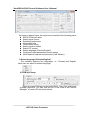
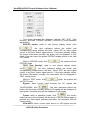
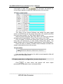
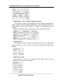
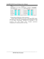
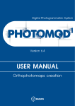
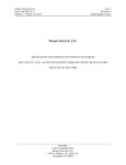
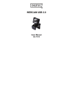
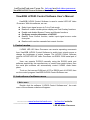
LedControlCard.com Focus On led card and led video processor ViewRGB LVP605 Control Software User’s Manual ViewRGB LVP605 Control Software User’s Manual ViewRGB LVP605 Control Software is used to control LED HD Video Processor. With this software, we can: z z z z z z Select input signal source in Cut or Fade mode. Realize 4 custom double-picture display and Text Overlay functions Enable and disable Bypass, Freeze and Mosaic functions Configure mosaic parameters of LVP605 Realize Timer Control function, switch input signal source under timer plan Realize multi-machine cascade fast mosaic function I. Control modes LVP605 LED HD Video Processor can receive operating commands from ViewRGB LVP605 Control Software to switch input signal source or change the brightness of output images. The LVP605 Control Software controls LVP605 LED HD Video Processor via RS232 COM serial port of PC. User can operate PVP605 manually using the RS232 serial port software supplied by the manufacturer, or create timer control plans, then the serial port software will automatically control LVP605 under these plans. To do so, first connect COM port of PC to RS232 port of LVP605, then run the control program ViewRGB LVP605 Control Software.exe. II. Instructions of software menu 1. Main menu Double click the software “LVP605 Control Software.exe”, the main menu of the software as below will appear: -------------------www.ledcontrolcard.com led control website. --------------------------------------------------------------------------------1 LED HD Video Processor ViewRGB LVP605 Control Software User’s Manual As shown in above figure, the main menu consists of the following parts: z RS232 COM port setup z Select signal source z Switching mode setup z Information field z Timer control setup z Select function modes z Select PIP modes z Select language (Chinese/English) z Configure output parameters (screen setup) z Multi-machine cascade mosaic setup (Fast Mosaic) 1) Select language (Chinese/English) The software supports two languages, i.e.: Chinese and English. Here user can select a desired language. 2) COM port setup Select a proper COM port in the field RS232_Com_Port, and select a proper device ID. You can view the No. of the COM in the “Device Manager” of control PC as shown below: --------------------------------------------------------------------------------------------------LED HD Video Processor 2 ViewRGB LVP605 Control Software User’s Manual The device ID you selected (from user setup item 21 “Device ID”) must be identical to the device ID of LVP605 to be controlled. Click the button “Connect”, the following message will appear . After the device is successfully connected, the function keys in the main menu of the software will be activated, and the following message will appear in the information field of main menu Timer Start Setup: to set whether the machine automatically connects serial port or starts timer control or not when it is started next time. 3) Signal status and signal switching The buttons of this area respectively represent the corresponding keys and status indicators in the panel of the processor. After the device is successfully connected, the software will read the input signal source you currently selected and the blue indicator above it will turn on. If the blue indicator illuminates normally, it means the input signal source you currently selected is valid; however, if the blue indicator blinks, it means there are no valid signal input. Click the signal button to change the input source of LVP605. The software can display the information of current extended modules. 4) Switching mode setup This function is used to setup signal switching modes. The system provides 4 switching modes, i.e.: Cut, Fade in fade out 0.5s, Fade in fade out 1.0s, Fade in fade out 1.5s. --------------------------------------------------------------------------------------------------LED HD Video Processor 3 ViewRGB LVP605 Control Software User’s Manual 5) Select function modes This menu provides the following options: PIP, TEXT (Text Overlay), BYPASS, FREEZE, MOSAIC, VGA-AUTO (VGA automatic adjustment). PIP/POP modes: while in one picture display mode, click , the blue indicators before the button and corresponding mode buttons will blink, select PIP as input signal source in the field “Select signal source”. If the blue indicator before the button illuminates normally, the picture will be displayed in PIP mode. User can select the preset PIP/POP display effects in the field “PIP_Mode”. While in PIP/POP mode, click , the system will exit PIP/POP mode. TEXT (Text Overlay): while in one picture display mode, click , the blue indicators before the button and corresponding mode buttons will blink, select TEXT as input signal source in the field “Select signal source”. If the blue indicator before the button illuminates normally, the information will be displayed in TEXT overlay mode. While in TEXT mode, click again, the system will exit TEXT mode. Bypass: when current input sources are PC signals like , the blue indicators before the VGA/DVI/HDMI, click button will illuminate normally, and the PC signals will be displayed in part screen, otherwise they will be displayed in full screen. Freeze: while in operation mode, click , the current output picture in the processor will be frozen. Click the button again or perform any other signal switching operation, the processor will exit Freeze mode. VGA-AUTO: when current input source is VGA signal and the --------------------------------------------------------------------------------------------------- 4 LED HD Video Processor ViewRGB LVP605 Control Software User’s Manual input signal is valid, click , the processor will sample the current input signals to make the output pictures full and clear. 5) Timer control setup The Timer of the Control Software can switch the input signal source of LVP605 as per the preset timer plan. The system provides four cycle timer modes, i.e.: Day, Week, Month, Once. Select a preset timer plan, then click “Start”, the Timer you selected will start to work immediately. To stop Timer control, click “Stop”. Click “Program” to enter timer setup menu, where you can view the timer plan you already set, or add, modify, delete timer plans. For details, please refer to the Chapter “Instructions of Timer Setup Menu” Once the timer is started, LVP605 Control Software shouldn’t be closed, otherwise the timer will not work. 6) Information If an operation fails, the reason for which current operation fails will appear in the information field. 2. Output parameters configuration (screen setup) menu Click , in main menu, the system will enter output parameters configuration menu as shown below: --------------------------------------------------------------------------------------------------LED HD Video Processor 5 ViewRGB LVP605 Control Software User’s Manual Other parameters configuration PIP setup Mosaic setup As shown in above figure, the button “Refresh” is used to update the information of currently processing parameters after parameters configuration is finished. Any abnormal of parameter will be reminded in info field. The current output resolution of the processor is displayed in software interface, but it can’t be set by the software. In addition, among all parameters appearing in the menu, those in walhet background color are the parameters not yet entered or saved; while those in grey background color are the parameters already saved. See the figure on the right hand: . Screen output parameters configuration include the following items: 1) Image input/output parameters configuration and mosaic mode setup. The parameters of output windows should be configured to the actual pixels of the screen to be driven. Mosaic mode setup and input image parameters configuration apply --------------------------------------------------------------------------------------------------LED HD Video Processor 6 ViewRGB LVP605 Control Software User’s Manual to multi-machine parallel mosaic only. The mosaic options are provided to set whether the processor adopts synchronous or non-synchronous mosaic mode. Input image parameters are used to set the location and size of the images to be captured from input image based on the actual size of the screen. Caution: input image parameters shall not be configured unless the following conditions are met: a. The input signal of the processor is DVI. b. The resolution of DVI input signals is the same with output resolution of the processor. c. The processor is in Mosaic state (the Mosaic indicator illuminates normally). 2) POP/PIP display setup (location and size of PIP windows) This menu is used to set the four PIP/POP display modes of LVP605. First, select a PIP mode to be adjusted, then enter the parameters of background, location and size of PIP windows, then click “Save” button to save the parameters in the processor. 3) TEXT setup It is used to set the red, green and blue threshold values of valid information of the text signals to be captured by the processor, also to set whether the text is greater or less than threshold values, select appropriate threshold values, click “Save” button to save them in the --------------------------------------------------------------------------------------------------LED HD Video Processor 7 ViewRGB LVP605 Control Software User’s Manual processor. 4) Brightness, color, contrast, sharpness setup This option is used to set brightness, color, contrast, sharpness of output images, enter the desired parameters, then click “Save” button. To set sharpness, directly click “Normal” or “Sharp”, the parameters will be saved. Notes: the default values of brightness, color, contrast are all 50. 5) Audio setup This option is used to set AD1, AD2 audio port as the corresponding video input port, so as to realize synchronous switching of audio/video signals. 6) Hot spare setup This option is used to turn on/off the hot spare function of the following four groups of input signals. --------------------------------------------------------------------------------------------------LED HD Video Processor 8 ViewRGB LVP605 Control Software User’s Manual 3. Timer setup menu Click in main menu, the system will enter Timer setup menu as shown below: As shown in above figure, there are two types of plans: Cycle Plan Once Plan) Cycle Plan is sub-divided into three types: Day Plan Week Plan Month Plan User can select one type he desires The plan items of Day Plan define hours, minutes, seconds; Each week has 7 days, so the plan items of Week Plan define week day, hour, minute, second; Each month has maximum 31 days, so the plan items of Month Plan define date, hours, minutes, seconds; The plan items of Once Plan define year, date, hours, minutes, seconds; --------------------------------------------------------------------------------------------------LED HD Video Processor 9 ViewRGB LVP605 Control Software User’s Manual Cycle plan and once plan can work together. For each type of plan, the plan items can be added, modified, deleted. For example, the figure below shows how to add plan items to a day plan. Select the plan already added, then you can modify or delete it. 3. Fast Mosaic menu LVP605 can drive ultra high-definition LED display through multi-machine cascade mosaic. User can complete input/output parameters configurations of each ser of processor through fast mosaic menu. In this menu, user only need select mosaic mode (namely how a large is divided into a number of smaller pieces of LED) and the actual pixels of each LED driven by each set of processor, the program will automatically calculate the mosaic parameters of each set of processor and save them in the corresponding processor. Enter Fast Mosaic Menu: after entering main menu of LVP605, click , the menu as below will pop up. --------------------------------------------------------------------------------------------------LED HD Video Processor 10 ViewRGB LVP605 Control Software User’s Manual Caution: before making the mosaic settings, please make sure the following conditions have been met: 1) All processors are the same with each other in brightness, color, contrast and definition. 2) All processors must use the same output resolution, and make sure it the same with that of input DVI signals. 3) The current input source of all processors is DVI signals, and make sure the Mosaic function is enabled (Mosaic indicator illuminates normally). Steps of Mosaic setup: Before performing mosaic setup, make sure that each LED display and processor are working well, and that each LED display is able to display a full picture independently. Connect all the processors or the first processor to be adjusted via serial ports. 1) Connect processors using software. Select the device ID of the first processor to be adjusted (from user setup item 21 “Device ID”), click “Connect”, the processor will automatically connect the processor, the software will read and --------------------------------------------------------------------------------------------------LED HD Video Processor 11 ViewRGB LVP605 Control Software User’s Manual display the current parameters (e.g.: output resolution) of the processor. . 2) Select mosaic mode Select current mosaic mode in “Specification” field, namely set how many rows and columns the divided pieces of smaller LED will be arranged. User can also manually enter the number of rows and columns then click “OK”. For the LED of 3648x2016 pixels, it should select 2x2 mosaic mode. 3) Enter actual parameters of each LED After selecting proper mosaic mode, the field “Effects shoe” will display the actual layout of each LED in models, enter the width and height of each LED display in turn as shown in Figure below: Enter the width value of corresponding LED. Selection button Enter the height value of corresponding LED. 4) Parameters configurations of the first processor Select the No. of the LED for showing effect in the field “Effects show” (we select the first LED ), click “Auto calculate”, the processor will automatically calculate the due parameter values of current processor based on the parameters entered in “Effects show”. Select the Mosaic mode you desire, and select Sync Mosaic for the LED, the software will pop up the message “Configuration is successful”. Click “Set” button respectively in input and output field, the software will automatically save the parameters that it worked out in current processor. Caution: both input and output parameters of LVP605 must be even, but the results of auto calculation may be odd, if so, it is necessary to set an adjusted value to correct the parameters to be even, then you can click “Set” to save it. --------------------------------------------------------------------------------------------------LED HD Video Processor 12 ViewRGB LVP605 Control Software User’s Manual 5) Parameters configuration of other processors. Connect other processors to be set in turn using RS232 cable, select device ID, select No. of corresponding LED following above step 4), the system automatically calculates the parameters of the processor, then select Mosaic mode. Complete parameters configurations of other processors in this way. --------------------------------------------------------------------------------------------------LED HD Video Processor 13