1
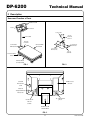
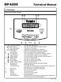
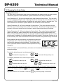
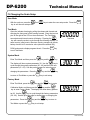
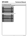
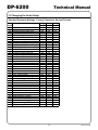
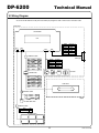
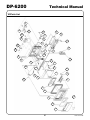
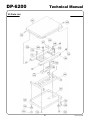
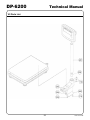
DP-6200
Technical Manual
YAMATO CORPORATION
1775 S. Murray Blvd.
Colorado Springs, CO 80916 USA
Tel (719) 591-1500 Fax (719) 591-1045
YAMATO TECH CORPORATION
#112-19425 Langley By-Pass
Surrey, B.C. V3S 6K1 Canada
Tel (604) 533-2338 Fax (604) 533-0827
YCO-1112-04-06
DP-6200
Technical Manual
Table of Contents
I.
Safety Instructions
1
II.
Description
Name and Function of Parts
Specifications
2
III.
Calibration
5
IV.
Changing the Scale Setup
Changing Parameters
User Mode
Test Mode
System Mode
Factory Mode
Standard Parameter Tables
Parameter Descriptions
6
V.
Troubleshooting
17
VI.
Wiring Diagram
19
VII. Parts List
20
YCO-1112-04-06
DP-6200
I
Technical Manual
Safety Instructions
Before using the scale, carefully read, understand, and follow the “Safety Instructions” described in this manual. Observe the
advice given in the “Directions for Use” section to ensure proper operation. Keep this operation manual handy for reference.
To prevent injury
1) DO NOT SHOCK LOAD the scale, Never step on or sit on the scale. Not only will the scale be damaged, but you may
also be injured.
2) DO NOT APPLY DIRECT WATER SPRAY to the scale if it is powered by an AC adaptor!! You could receive a shock. The
scale is not washdown unless the AC jack is plugged with a water-tight seal.
4) Do not operate the scale if there is smoke or a burnt smell coming from the scale. Remove the batteries or unplug the
AC adaptor immediately. After making sure that there is no danger, consult your dealer. Never try to repair the scale
by yourself.
5) This scale is not an explosion-proof model. Do not use the scale in an atmosphere containing flammable gases or
explosive fumes. A fire or an explosion can result.
6) Place the item to be weighed in the center of the platform. Items placed on the edge of the platform may fall off and
cause injury.
7) When weighing a heavy, large or unbalanced item, make sure the item is stable on the platform, otherwise an accident
may occur.
8) When carrying or moving the scale, be sure to hold it by the bottom of the weighing platform with both hands. If you hold
it by the column, the column may become detached causing the scale to fall. This will damage the scale and could cause
injury.
9) Do not insert your finger into the gap or holes in the scale. You may be injured.
10) The DP-6200 uses a liquid crystal display. If the LCD breaks and the liquid leaks from the LCD, do not touch it with your
fingers. The liquid is toxic if ingested. Be especially careful around small children.
To prevent damage to the scale
1) Do not push the indicator or keys with sharp objects. They may break or puncture the switch membrane panel.
2) Use the specified power supply and choose a suitable environment. If you do not, the weight readings may be inaccurate
and the scale may be damaged.
3) The scale is a sensitive weighing instrument, avoid physical shocks. If you drop something on the scale, overload the
scale, step on the platform, or drop the scale, the scale may be damaged and lose accuracy.
4) If the scale becomes dirty, wipe it with a soft cloth. For stubborn stains, apply a little neutral detergent and then wipe the
scale with a dry cloth. Do not use thinner, benzene, hot water, or chemical agents, all of which can cause deformation, discoloration, or deterioration of the scale.
5) Never remove the case. The fine adjustment section may be damaged and you may be injured by sharp edges on the
internal parts.
6) Do not place the scale upside down.
7) When the low battery indicator appears, replace all six of the batteries. When installing the batteries, install them according to the polarity markings in the case (+, -). If the scale will not be used for a long period, remove the batteries.
8) Never connect or disconnect the RS-232 cable while the DP-6200 and a connected computer are on. The DP-6200 and/or
the computer may be damaged. RS-232 ports are not hot-swappable.
To keep the scale working efficiently
1) Place the scale on a flat stable surface that will support the scale and the load.
2) Do not place the scale in an area exposed to direct sunlight or to wind currents from an air conditioner, otherwise, the measurements will not be accurate.
3) Do not place the scale near machines that create vibrations or electromagnetic disturbance, such as microwave ovens,
portable phones, or large motors. This will affect the accuracy.
4) The operating temperature range is from –5°C to +35°C (23°F to 95°F). Do not subject the scale to sudden temperature
changes; allow the scale to adjust to the new temperature before use.
5) If the scale is sealed, do not break the seal. If you break the seal, the scale will not be considered legal for trade. In this
case, contact your dealer.
6) Do not disassemble or modify the scale, you will void the warranty. Modified scales will not be legal for trade.
1
YCO-1112-04-06
DP-6200
Technical Manual
II Description
Name and Function of Parts
���������
���
����
������
����
�����
����
������
�����
�����
������
�������
��������
�����
�������
������
������
�������
����
�����
���������
����
��������
��������
FIG. 1
FIG. 2
����������
�����
�����
�������
���
�����
����������
������
����������
����
��������
������
����
���������
��������
FIG. 3
2
YCO-1112-04-06
DP-6200
Technical Manual
II Description
Name and Function of Parts
�
�
�
�
��
��
����
������
�����
�
����
��� �����
�
��������
�������������
�������������
�������
��
���
���
�
���
�����
����
�
1)
2)
3)
4)
5)
����
���
�����
6)
7)
8)
9)
Low Battery Indicator
Hold Indicator
Test Mode Indicator
Stable Indicator
LCD Display
Unit Indication
Over Indicator
Accept Indicator
Under Indicator
Mode Indicator
Net Indicator
Gross Indicator
Center of Zero Indicator
Net/Gross Key
Decrease Key
Unit Selection Key
On/Zero Key
Next Key
Off Key
Tare Key
Increase Key
Unit Selection Key
�
FIG. 4
�
�
Time to replace the batteries.
The scale is in Hold mode (not legal-for-trade).
The scale is in Test Mode.
Indicates the weight indication is stabilized.
Shows all scale indications and weight readings.
KG, LB, OZ and LB-OZ (not legal-for-trade).
The current weight is over the user’s maximum setpoint.
The current weight is within the user’s setpoints.
The current weight is below the user’s minimum setpoint.
The scale is in setup mode.
The scale is indicating net weight.
The scale is indicating gross weight.
The scale is at gross zero.
Toggles between gross and net weight readings.
Decreases setpoints.
Press both keys simultaneously to toggle between kilogram and
either pound, ounce or pound-ounce units.
Turns the power on, and zeroes the display.
Moves to the next setpoint.
Turns the power off.
Tares off the current weight.
Increases setpoints.
Press both keys simultaneously to toggle between kilogram and
either pound, ounce or pound-ounce units.
3
YCO-1112-04-06
DP-6200
Technical Manual
II Description
Specifications
Weighing system:
Platform:
Weight display:
Type:
Character size, etc.:
Optional equipment:
Power supply:
Consumption:
Battery life:
Operating temperature:
Operating humidity:
Waterproof classification:
Capacities and divisions:
Kilogram
30 kg x 0.01 kg
60 kg x 0.02 kg
150 kg x 0.05 kg
Strain-gauge load cell
13.8” x 19.7” (350 x 500 mm), stainless steel
Single face display
7 segment LCD
0.5” (12 mm) (W) x 0.9” (23 mm) (H), 5 digits
Batteries, AC adaptor, RS-232C communications (the scale is not
washdown with the RS-232C option installed.)
9V DC - six “D” size batteries or AC adaptor (the scale is not
washdown unless the AC jack is plugged with a water-tight seal).
0.12 W (max.)
600 hours of continuous use with alkaline batteries. Using the RS232C option will substantially reduce battery life.
23°F to 95°F (-5°C to 35°C)
25% to 85% RH
Complies with NEMA 4 (washdown) when the AC jack is plugged
with a water-tight seal. Is not washdown with the RS-232C option
installed.
Pound
60 lb x 0.02
150 lb x 0.05 lb
300 lb x 0.1 lb
Ounce
960 oz x 0.5 oz
2400 oz x 1 oz
4800 oz x 2 oz
Pound-Ounce*
60 lb x 0.5 oz
150 lb x 1 oz
300 lb x 2 oz
* Combined units, such as pound-ounce, are not legal-for-trade.
The DP-6200 is available in four capacities. It displays units of kilograms and one of the following
three: decimal pounds, continuous ounces, or pounds and ounces. It is important to note that various
parameter settings depend upon the mode (decimal pound, continuous ounce, or pound and ounce)
option selected when the scale was purchased. See section IV - Changing the Scale Setup for the
standard settings for each mode.
The DP-6200 is not washdown unless the AC adaptor jack is sealed, or if the RS-232 option is installed.
Remove the batteries when operating the scale with the AC adaptor. Use only the AC adaptor supplied
or an adaptor of the same output characteristics.
4
YCO-1112-04-06
DP-6200
Technical Manual
III Calibration
The DP-6200 can be setup to be calibrated with pound weights or with kilogram weights. Check
the setting of system parameter 78 (see section IV - Changing the Scale Setup). 000 sets the scale
to be calibrated with kilogram weights, 001 sets the 60 lb and 300 lb scales to be calibrated with
pound weights, and 002 sets the 150 lb scale to be calibrated with pound weights.
1) Open the indicator housing by pulling the release tab forward and
swinging the front panel of the housing forward. Short the two test
pins to the right of the CPU on the main board. The Test Mode
ennunciator and internal counts will display.
��
Test Mode
���
�����
2) Press and hold the
key and press the
key. If the
scale indicates two point calibration mode, change it to three point
���
�����
calibration mode by pressing the
Two Point Mode
key.
If it becomes necessary to abort the calibration procedure before
��
completing it, press the
key to return to the test mode.
Three Point Mode
Zero Calibration
3) Remove all items from the scale platform, wait for the stable indicator to display and press the
�
key.
4) Place 1/2 the full capacity of the scale on the platform, wait for the
stable indicator to display and press the
�
key.
1/2 Capacity Calibration
5) Place the full capacity of the scale on the platform, wait for the
stable indicator to display and press the
�
key.
6) The scale will return to Test Mode and indicate full scale counts of
30000 for all kg, 27215 for 60 lb and 300 lb, and 34025 for 150 lb
calibration. The full scale counts should be within +/- 3 counts of
���
the appropriate target. Press the
key to exit Test Mode.
If the scale indicates error 103, then reconfirm that system parameter 78 is set correctly for the weights being used and the
capacity of the scale. Verify that the correct weights, 1/2 capacity and full capacity, are being used. Make sure that nothing is
restricting the motion of the platform, pressing against the platform
or wedged between the upper and lower platform. Remove any
sources of vibration or electromagnetic radiation (i.e. - cell phones,
power cables, motors, compressors, etc.) Repeat the calibration
procedure. If the error repeats, see section V - Troubleshooting.
5
Full Capacity Calibration
Full Scale Counts
Error 103
YCO-1112-04-06
DP-6200
Technical Manual
IV Changing the Scale Setup
Changing Parameters
The scale setup is controlled by three groups of parameters that determine how the scale operates.
These three groups are User Parameters, System Parameters and Factory Parameters.
User Parameters (00 - 09) can be changed in both User Mode and System Mode. They are easily
accessed, without breaking the seal or opening the indicator housing, and control functions such as
the auto-off, RS-232 communications and whether the scale starts in metric or standard units. The
User Parameters are included in System Mode for the convenience of the technician.
System Parameters (30 - 40) can be changed in System Mode. They control functions that the
technician may need to change under unusual circumstances. Since these functions can alter the
accuracy of the scale, the seal has to be broken to access System Mode through Test Mode.
Factory Parameters (51 - 99) can be change in Factory Mode. They control functions that directly
relate to the accuracy, capacity and divisions of the scale and are rarely changed outside of the
factory. Factory Parameters are usually only changed if a different standard mode (pound, ounce or
pound-ounce) is needed or if a different capacity load cell is installed. Since these functions can alter the accuracy of the scale, the seal has to be broken to access Factory Mode through Test Mode.
Each parameter has two components, the parameter keyword and
the parameter value. The first two digits are the keyword and determine which parameter is being changed. The last three digits
are the value and determine what the selected parameter is being
changed to.
�
Keyword
Value
While each mode is accessed differently, all modes use the same keys to select and change the
parameter settings.
To select the desired keyword, use the keys as follows:
��
��
- increase the keyword by one
���
�����
+
- decrease the keyword by one
To change a parameter value, use the keys as follows:
�
�
- increase the value by one
���
�����
���
�����
+
- increase the value by ten
���
�����
- decrease the value by one
+
�
- decrease the value by ten
To save the last value changed it is necessary to advance to the next keyword before exiting the
��
setup mode. Press and hold the
���
key and press the
tory Mode and return to Test Mode. Press the
���
6
�����
key to exit System Mode or Fac-
key to exit any setup or test mode.
YCO-1112-04-06
DP-6200
Technical Manual
IV Changing the Scale Setup
User Mode
��
With the scale on, press the
key to exit the user setup mode.
�
and
keys to enter the user setup mode. Press the
���
Test Mode
Open the indicator housing by pulling the release tab forward and
swinging the front panel of the housing forward. Short the two test
pins to the right of the CPU on the main board. The Test Mode
�
ennunciator and internal counts will display. Pressing the
key will cause the scale to cycle through the following displays: internal counts, initial counts, direct raw counts, average raw counts,
battery check/A to D conversion value (should be around 220),
ROM version and a display segment check. Press the
to exit Test Mode.
System Mode
���
��
Enter Test Mode and then press the
key and the
�
��
key
key.
The display will show system parameter 30. Use the
key to
cycle through the system parameters (30 - 40) and then the user
parameters (01 - 09). See the previous page for instructions on
��
changing the parameters. Press the
to return to Test Mode or press the
Factory Mode
key and the
���
�
System Mode
key
key to exit setup.
��
Enter Test Mode, press the
�
Test Mode
���
key and the
�����
key to enter
��
�
�
Calibration Mode, and then press the
key and the
key to enter Factory Mode. The display will show factory parame��
ter 99. Use the
key to cycle through the factory parameters
(50 - 99). See the previous page for instructions on changing the
��
parameters. Press the
Test Mode or press the
key and the
���
�
Factory Mode
key to return to
key to exit setup.
7
YCO-1112-04-06
DP-6200
Technical Manual
IV Changing the Scale Setup
Standard Parameter Settings - User Parameters
Key
Word
01
02
03
04
05
06
07
08
09
User Parameter
Auto-off timer
Display hold timer
Communication
Communication data
Communication speed
Character length
Parity
Stop bit length
Default mode
All
Cap.
015
000
001
000
000
000
000
001
001
Standard Parameter Settings - System Parameters
Key
Word
30
31
32
33
34
35
36
37
38
39
40
System Parameter
System ID
Gravity compensation
Linearity compensation
Steady-state sampling count
Steady-state count
Polarity steady-state count
Steady-state collapse count
Steady-state average count
Zero tracking timing
Neglectable change count
Simple test mode
All
Cap.
018
010
000
004
012
008
020
004
004
001
003
8
YCO-1112-04-06
DP-6200
Technical Manual
IV Changing the Scale Setup
Standard Parameter Settings - Factory Parameters, Decimal Pounds
Key
Word
51
52
53
54
55
56
57
58
59
60
61
62
63
64
65
66
67
68
69
70
71
72
73
74
75
76
77
78
79
80
81
82
91
92
93
94
95
96
97
99
Factory Parameter
30 kg
60 lb
Scale Mode
004
Multi-increments
000
Weighing capacity base value
003
Weighing capacity index value
003
Increment for lighter range
000
Location of decimal point
002
Type of decimal point
000
Weighing unit
002
Display of weighing unit
001
Weighing capacity base value (lb)
006
Weighing capacity index value (lb)
003
Location of decimal point
002
Pound increment
002
Pound conversion coefficient
003
Zero point range
019
Zero point range on plus side
012
Over scale
003
Display hold function
000
Hold release against increased wght. 000
Stable mark
000
Tare function
002
Zero reset under tare operation
001
Power off with ON key
000
Special function for stability
000
Over - under function
001
Tare cancel by Zero key toggle
000
-bat- display toggle
000
Conversion coefficient for lb cal.
001
Center-of-zero ennunciator position
001
Internal resolution
010
1 timer (ms)
060
3 timer (ms)
045
Mechanical zero 1
auto
Mechanical zero 2
auto
Span coefficient 1 (small)
auto
Span coefficient 2 (small)
auto
Span coefficient 1 (large)
auto
Span coefficient 2 (large)
auto
Regional # and gravity for span adj.
auto
Factory setting - Do not change
000
60 kg
150 lb
004
000
006
003
001
002
000
002
001
015
003
002
005
002
019
012
003
000
000
000
002
001
000
000
001
000
000
002
001
010
060
045
auto
auto
auto
auto
auto
auto
auto
000
9
150 kg
300 lb
004
000
015
003
002
002
000
002
001
003
003
001
001
003
019
012
003
000
000
000
002
001
000
000
001
000
000
001
001
010
060
045
auto
auto
auto
auto
auto
auto
auto
000
YCO-1112-04-06
DP-6200
Technical Manual
IV Changing the Scale Setup
Standard Parameter Settings - Factory Parameters, Continuous Ounce
Key
Word
51
52
53
54
55
56
57
58
59
60
61
62
63
64
65
66
67
68
69
70
71
72
73
74
75
76
77
78
79
80
81
82
91
92
93
94
95
96
97
99
Factory Parameter
30 kg 60 kg 150 kg
960 oz 2400 oz 4800 oz
Scale Mode
007
007
007
Multi-increments
000
000
000
Weighing capacity base value
003
006
015
Weighing capacity index value
003
003
003
Increment for lighter range
000
001
002
Location of decimal point
002
002
002
Type of decimal point
000
000
000
Weighing unit
002
002
002
Display of weighing unit
001
001
001
Weighing capacity base value (lb)
006
015
003
Weighing capacity index value (lb)
002
001
002
Location of decimal point
001
000
000
Pound increment
005
001
002
Pound conversion coefficient
001
001
002
Zero point range
019
019
019
Zero point range on plus side
012
012
012
Over scale
003
003
003
Display hold function
000
000
000
Hold release against increased wght. 000
000
000
Stable mark
000
000
000
Tare function
002
002
002
Zero reset under tare operation
001
001
001
Power off with ON key
000
000
000
Special function for stability
000
000
000
Over - under function
001
001
001
Tare cancel by Zero key toggle
000
000
000
-bat- display toggle
000
000
000
Conversion coefficient for lb cal.
001
002
001
Center-of-zero ennunciator position
001
001
001
Internal resolution
010
010
010
1 timer (ms)
060
060
060
3 timer (ms)
045
045
045
Mechanical zero 1
auto
auto
auto
Mechanical zero 2
auto
auto
auto
Span coefficient 1 (small)
auto
auto
auto
Span coefficient 2 (small)
auto
auto
auto
Span coefficient 1 (large)
auto
auto
auto
Span coefficient 2 (large)
auto
auto
auto
Regional # and gravity for span adj.
auto
auto
auto
Factory setting - Do not change
000
000
000
10
YCO-1112-04-06
DP-6200
Technical Manual
IV Changing the Scale Setup
Standard Parameter Settings - Factory Parameters, Pound and Ounce
Key
Word
51
52
53
54
55
56
57
58
59
60
61
62
63
64
65
66
67
68
69
70
71
72
73
74
75
76
77
78
79
80
81
82
91
92
93
94
95
96
97
99
Factory Parameter
30 kg
60 lb
Scale Mode
005
Multi-increments
000
Weighing capacity base value
003
Weighing capacity index value
003
Increment for lighter range
000
Location of decimal point
002
Type of decimal point
000
Weighing unit
002
Display of weighing unit
001
Weighing capacity base value (lb)
006
Weighing capacity index value (lb)
002
Location of decimal point
001
Pound increment
005
Pound conversion coefficient
001
Zero point range
019
Zero point range on plus side
012
Over scale
003
Display hold function
000
Hold release against increased wght. 000
Stable mark
000
Tare function
002
Zero reset under tare operation
001
Power off with ON key
000
Special function for stability
000
Over - under function
001
Tare cancel by Zero key toggle
000
-bat- display toggle
000
Conversion coefficient for lb cal.
001
Center-of-zero ennunciator position
001
Internal resolution
010
1 timer (ms)
060
3 timer (ms)
045
Mechanical zero 1
auto
Mechanical zero 2
auto
Span coefficient 1 (small)
auto
Span coefficient 2 (small)
auto
Span coefficient 1 (large)
auto
Span coefficient 2 (large)
auto
Regional # and gravity for span adj.
auto
Factory setting - Do not change
000
60 kg
150 lb
005
000
006
003
001
002
000
002
001
015
001
002
001
001
019
012
003
000
000
000
002
001
000
000
001
000
000
002
001
010
060
045
auto
auto
auto
auto
auto
auto
auto
000
11
150 kg
300 lb
005
000
015
003
002
002
000
002
001
003
002
002
002
002
019
012
003
000
000
000
002
001
000
000
001
000
000
001
001
010
060
045
auto
auto
auto
auto
auto
auto
auto
000
YCO-1112-04-06
DP-6200
Technical Manual
IV Changing the Scale Setup
Parameter Descriptions - User Parameters
Key
Word
01
Std
Value
015
Function
Auto-off timer
02
000
Display hold timer
03
001
Communication
04
000
Communication data
05
000
Communication speed
06
000
Character length
07
002
Parity
08
001
Stop bit length
09
001
Default mode
Description
000 Disables auto-off.
001~240 Number of minutes unused to activate auto-off.
000 No display hold for changes less than four divisions.
001~030 Display hold duration, in seconds, for changes less
than four divisions.
031 No display hold.
000 No serial interface.
001 Specified commands acceptable.
002 Sends zero detection.
003 Sends motion detection.
004 Sends continuously.
000 Net weight (1 batch)
001 Net weight, tare weight, gross weight (1 batch)
002 Net weight, tare weight, gross weight (3 batches)
003 Display content (1 batch)
004 Serial printer format (1 batch)
000 9600 bps
001 600 bps
002 1200 bps
003 2400 bps
004 4800 bps
005 9600 bps
006 19200 bps
007 38400 bps
000 8 bits
001 7 bits
000 Non
001 Odd
002 Even
000 1 bit
001 2 bits
000 kg
001 lb/oz
12
YCO-1112-04-06
DP-6200
Technical Manual
IV Changing the Scale Setup
Parameter Descriptions - System Parameters
Key
Word
30
31
Std
Value
018
010
Function
System ID
Gravity compensation
32
000
Linearity compensation
33
34
35
36
37
38
004
012
008
020
004
010
Steady-state sampling count
Steady-state count
Polarity steady-state count
Steady-state collapse count
Steady-state average count
Zero tracking timing
39
40
001
000
Neglectable change count
Simple test mode
Description
018 Do not change.
000 No compensation.
001~016 Compensation for a specified area (Japan only.)
017~150 Acceleration due to gravity formula, (mm/s2 )-9700.
000 No compensation.
001~127 Positive compensation.
128~255 Negative compensation.
000~255
000~255
000~255
000~255
000~255
000 Disable zero tracking
001~255 Zero tracking at specified counts
000~010 Number of counts
000 User parameter valid
001 User parameter invalid
002 User parameter and simple test mode valid
003 User parameter and simple test mode invalid
13
YCO-1112-04-06
DP-6200
Technical Manual
IV Changing the Scale Setup
Parameter Descriptions - Factory Parameters
Key
Word
51
Function
Scale mode
52
Multi-increments,
complex increment mode
53
54
55
Weighing capacity base value
Weighing capacity index value
Increment for lighter range
56
Location of decimal point
57
Type of decimal point
58
Weighing unit
59
Weighing unit display
60
Weighing capacity base value
(pound mode)
Weighing capacity index value
(pound mode)
61
Description
000 Fixed single increment.
001 Multi-increments.
002 Do not use.
003 Do not use.
004 Change-over / gram mode - decimal pound mode.
005 Change-over / gram mode - lb/oz mode.
006 lb/oz mode.
007 Change-over / gram mode - continuous ounce mode.
000 Fixed single increment.
001 Fixed accuracy, 3 increments.
002 Fixed accuracy, 2 increments.
003 Increment change at 50% full scale, 2 increments.
004 Increment change at 80% full scale, 2 increments.
005 Increment change at 64% full scale, 2 increments.
006 Increment change at 40% full scale, 2 increments.
000~099
001~004
000 1
001 2
002 5
003 10
004 20
005 50
006 100
007 200
000 0 (No decimal point.)
001 0.0
002 0.00
003 0.000
004 0.0000
000 Period (.)
001 Comma (,)
000 No unit.
001 g
002 kg
003 lb.
004 oz.
000 No display.
001 Specified unit displayed.
000 Not used in pound mode.
001~099
000~004
14
YCO-1112-04-06
DP-6200
Technical Manual
IV Changing the Scale Setup
Parameter Descriptions - Factory Parameters (continued)
Key
Word
62
Function
Location of decimal point
(lb , oz or lb/oz mode)
63
64
Pound increment
Pound conversion coefficient
65
66
67
68
Zero point range
Zero point range on plus side
Over scale
Display hold function
69
70
Hold release against
increased weight
Stable mark
71
Tare function
72
Zero reset under tare operation
73
Power off with ON key
74
Special function for stability
75
Over - under feature
76
Tare cancel by zero key toggle
77
-bat- display toggle
Description
<Decimal pound and decimal ounce modes>
000 0 (No decimal point)
001 0.0
002 0.00
003 0.000
004 0.0000
<Pound/ounce mode>
000 0 : 0.00
001 0 : 0.0
002 0 : 0
003~004 Not used.
000~008
000 Conversion coefficient = 1.00000
001 Conversion coefficient = 0.705479
002 Conversion coefficient = 0.881849
003 Conversion coefficient = 1.10231
000~100
000~100
000~010
000 No hold
001 Hold for weight more than net + 10 divisions.
002 Hold for weight more than net + 10 divisions, hold key invalid.
003 Hold for weight more than net + 20 divisions.
004 Hold for weight more than net + 20 divisions, #10 invalid.
005 Hold for weight more than net + 20 divisions, hold key invalid,
#10 invalid.
000 Hold against any increased weight.
001~005 Hold release against a specified increase.
000 Display the stable mark.
001 Stable mark not displayed.
000 No tare function.
001 One-time tare.
002 Consecutive tare.
000 Zero reset enabled.
001 Zero reset disabled.
000 ON key disabled for power off.
001 Power off after pressing ON key for two seconds.
000 No function.
001 Enforcement.
002 EU mode.
000 Disabled.
001 Enabled.
000 Disabled.
001 Enabled.
000 Enabled.
001 Disabled.
15
YCO-1112-04-06
DP-6200
Technical Manual
IV Changing the Scale Setup
Parameter Descriptions - Factory Parameters (continued)
Key
Word
78
79
Function
Conversion coefficient for
pound calibration
80
Center-of-zero ennunciator
position toggle
Internal resolution
81
1 timer (ms)
82
3 timer (ms)
91
92
93
94
95
96
97
Mechanical zero 1
Mechanical zero 2
Span coefficient 1 (small)
Span coefficient 2 (small)
Span coefficient 1 (large)
Span Coefficient 2 (large)
Regional number and gravity
for span adjustment
Factory setting
99
Description
000 Kilogram calibration for all capacities.
001 Pound calibration for 60 lb and 300 lb capacity scales.
002 Pound calibration for 150 lb capacity scales.
000 Alternate.
001 NTEP.
000 Do not use.
001~255
000 Do not use.
001~255
000 Do not use.
001~255
000~255 Automatically set at span adjustment.
000~255 Automatically set at span adjustment.
000~255 Automatically set at span adjustment.
000~255 Automatically set at span adjustment.
000~255 Automatically set at span adjustment.
000~255 Automatically set at span adjustment.
000~155 Automatically set at span adjustment.
000 Always displayed. * Do Not Change *
16
YCO-1112-04-06
DP-6200
Technical Manual
V Troubleshooting
The scale can check various functions automatically. When a problem is detected, the following messages will be displayed. Solutions are listed in order of decreasing probability and increasing complexity.
The batteries are running low. When the batteries are running
low, this indicator will come on. Replace all of the batteries with
new ones.
��
The batteries are low. When the batteries are too low for accurate operation, this indication will be displayed and the scale may
automatically power off. The batteries must be replaced to use
the scale.
Weight out of range high. When the weighed value is 6 or more
divisions heavier than the scale’s capacity this message will be
displayed. Remove any excess weight from the scale platform.
Calibrate the scale. Replace the logic board and/or load cell.
Weight out of range low. When the weighed value is a few divisions below calibrated zero, this message will be displayed. It is
usually displayed when the platform is removed or has something
wedged under it. Place the platform on the platform support or remove any objects wedged under the platform. Calibrate the scale.
Replace the logic board and/or load cell.
Initial error on startup, high. When the initial weight is heavier
��
than the permissible zeroing range and the
key is pressed,
this message will be displayed. Remove whatever is on the plat��
form and press the
key again. Calibrate the scale. Replace
the logic board and/or load cell.
Initial error on startup, low. When the initial weight is lighter
��
than the permissible zeroing range and the
key is pressed,
this message will be displayed. It is usually displayed when the
platform is removed or has something wedged under it. Place the
platform on the platform support or remove any objects wedged
��
under the platform, and press the
key again. Calibrate the
scale. Replace the logic board and/or load cell.
17
YCO-1112-04-06
DP-6200
Technical Manual
V Troubleshooting
Weighing sensor error. When the weight detecting circuitry registers an error, this message will be displayed. Turn the power off
and then on again. Calibrate the scale. Replace the load cell.
Electronic circuitry error. When the operating circuitry registers
an error, this message may be displayed. Turn the power off and
then on again. Replace the logic board.
Calibration points out of range error. Occurs after the scale is
calibrated, but the value of the calibration points are outside the
range of the software. Confirm that system parameter 78 is set
correctly for the weights being used and the capacity of the scale.
Verify that the correct weights, 1/2 capacity and full capacity, are
being used. Make sure that nothing is restricting the motion of the
platform, pressing against the platform or wedged between the
upper and lower platform. Remove any sources of vibration or
electromagnetic radiation (i.e. - cell phones, power cables, motors,
compressors, etc.) Repeat the calibration procedure. Replace the
logic board and/or load cell.
Electromagnetic disturbance error. This indication is occasionally displayed due to strong static electricity and/or electromagnetic disturbance. Move the scale away from any sources
of electromagnetic radiation (motors, generators, power cables,
transmitters, etc.) Turn the power off and then on again. If an
AC adapter is being used, try using a different power circuit or AC
adapter. Replace the logic board.
18
YCO-1112-04-06
DP-6200
Technical Manual
VI Wiring Diagram
������������������������������������������������������������������������������������������������������������������
���������
���������
���
���
� �
���
�
�
���
���
�
���
���
���
���
���
���
�
�
���
���
���
���
���
������ �������
����
����
������� ���������
�������
���
������
���
�
������ ������� �
������
���� �
�������
���� �
����
���� �
�������
���� �
������
���� �
������������
����������
���
������
����
��
���
������
����
��
���
������
���
��� ���������
���
����
���
��
���
���������
�����
��� ������������� ����
��
��� ������������ ����
��
���
������
���
��
���
����
���
���
�
������
���������
������������
���
���
��
������
������
���
��
����
���������������
������������
���
���
����
������
��
���
�����������
19
YCO-1112-04-06
�
�
20
���
��
�
�
�
�
��
��
��
�
�
�
��
�
��
�
��
��
��
��
��
��
��
�
��
��
��
��
��
���
��
��
��
��
��
��
��
��
��
��
��
DP-6200
Technical Manual
VIIParts List
YCO-1112-04-06
DP-6200
Technical Manual
VII Parts List
21
YCO-1112-04-06
DP-6200
Technical Manual
VII Parts List
22
YCO-1112-04-06
DP-6200
Technical Manual
VII Parts List
ITEM
1
2
3
4
5
6
7
8
9
10
11
12
13
14
15
16
17
18
19
20
21
22
23
24
25
26
27
28
29
30
31
32
33
34
35
36
37
38
39
40
41
42
43
44
45
46
47
PART NUMBER
YAM-1235-620001
YAM-1235-620002
YAM-1235-620003
YAM-1235-620004
YAM-1235-620005
YAM-1235-620006
YAM-1235-620007
YAM-1235-620008
YAM-1235-620009
YAM-1235-620010
YAM-1235-620011
YAM-1235-620012
YAM-1235-620013
YAM-1235-620014
YAM-1235-620015
YAM-1235-620016
YAM-1235-620017
YAM-1235-620018
YAM-1235-620019
YAM-1235-620020
YAM-1235-620021
YAM-1235-620022
YAM-1235-620023
YAM-1235-620024
YAM-1235-620025
YAM-1235-620026
YAM-1235-620027
YAM-1235-620028
YAM-1235-620029
YAM-1235-620030
YAM-1235-620031
YAM-1235-620032
YAM-1235-620033
YAM-1235-620034
YAM-1235-620035
YAM-1235-620036
YAM-1235-620037
YAM-1235-620038
YAM-1235-620039
YAM-1235-620040
YAM-1235-620041
YAM-1235-620042
YAM-1235-620043
YAM-1235-620044
YAM-1235-620045
YAM-1235-620046
YAM-1235-620047
DESCRIPTION
Front Mask
Front Glass
Housing, Indicator, Front
Gasket, Front, Indicator
Logic Board Assembly
Keyboard Assembly
Key Top, Plastic
Screw, Tapping, M3x8 with Felt Washer
Screw, Tapping, M3x8
Logic Board Cover Plate
Screw, Sealing, M3x10
Plate, Cable Cover
Housing, Indicator, Rear
Fulcrum Shaft, Latch Assembly
Bracket, Indicator, Latch
Indicator Latch Spring Bracket
Fulcrum Shaft, Hinge Side
Battery Box Mounting Plate
Screw, Phillips, Pan, M3x10
Battery Holder
Screw, Tapping, M3x6, Washer
Screw, Tapping, M3x13, Washer
Screw, Tapping, M4x10
Cable, AC Adapter Jack
Nut, Hex, M2, SS
Screw, Phillips, Round, M2x10, SS
Screw, Phillips, Round, M4x10, SS
Bracket, Pole, Adjustable
Angle Adjuster
Spring, Angle Adjuster
Gasket, Pole, Cover
Cover, Pole
Screw, Tapping, M4x16, SS
Bracket, Button Support
Button, Square, Angle Adjust
Screw, Tapping, M3.5x12
Sticker, Cover, Ports
Serial Plate
Sticker, Capacity, 60 lb x 0.02 lb
Sticker, Capacity, 60 lb x 0.5 oz
Sticker, Capacity, 960 oz x 0.5 oz
Sticker, Capacity, 150 lb x 0.05 lb
Sticker, Capacity, 150 lb x 1 oz
Sticker, Capacity, 2400 oz x 1 oz
Sticker, Capacity, 300 lb x 0.1 lb
Sticker, Capacity, 300 lb x 2 oz
Sticker, Capacity, 4800 oz x 2 oz
23
QTY.
1
1
1
1
1
1
1
4
7
1
2
1
1
2
1
2
2
1
1
1
1
2
1
1
2
2
1
1
1
1
1
1
2
1
1
1
1
1
1
1
1
1
1
1
1
1
1
YCO-1112-04-06
DP-6200
Technical Manual
VII Parts List
ITEM
101
102
103
104
105
106
107
108
109
110
111
112
113
114
115
116
117
118
119
120
121
122
123
124
125
126
201
202
203
204
205
206
207
PART NUMBER
YAM-1235-620101
YAM-1235-620102
YAM-1235-620103
YAM-1235-620104
YAM-1235-620105
YAM-1235-620106
YAM-1235-620107
YAM-1235-620108
YAM-1235-620109
YAM-1235-620110
YAM-1235-620111
YAM-1235-620112
YAM-1235-620113
YAM-1235-620114
YAM-1235-620115
YAM-1235-620116
YAM-1235-620117
YAM-1235-620118
YAM-1235-620119
YAM-1235-620120
YAM-1235-620121
YAM-1235-620122
YAM-1235-620123
YAM-1235-620124
YAM-1235-620125
YAM-1235-620126
YAM-1235-620201
YAM-1235-620202
YAM-1235-620203
YAM-1235-620204
YAM-1235-620205
YAM-1235-620206
YAM-1235-621999
DESCRIPTION
Cover, Top, SS
Screw, Tapping, M4x12, SS
Plug, Spider, End Cap
Spider, Top
Plate, Grounding, Spring
Bolt, Hex, M6x12
Cushion, Rubber, Top Spider
Screw, Hex, Socket, Load Cell, M10x25
Washer, Lock, Load Cell, M10
Screw, Hex, Socket, Load Cell, M10x45
Nut, Hex, M6
Screw, Phillips, Round, M6x25
Load Cell, 75 kg for 60 lb
Load Cell, 150 kg for 150 lb
Load Cell, 300 kg for 300 lb
Spider, Bottom
Cover, Bottom, SS
Screw, Phillips, Round, M4x10, SS
Leg, Level
Nut, Hex, M10, SS
Cap, Rubber for Level Leg
Bubble Level
Bracket, Level, Bubble
Screw, Phillips, Round, M4x15, SS
Sticker, Warning, Cover, Top
Washer, Flat, M10
Pole
Collar, Pole, Internal
Bracket, Pole
Screw, Hex, Socket Head, M6x25
Clip, Cover, Bracket Pole
Cover, Bracket, Pole
Option, RS-232 (not shown)
24
QTY.
1
4
4
1
1
1
9
4
8
4
4
4
1
1
1
1
1
7
4
4
4
1
1
1
1
4
1
1
1
4
1
1
1
YCO-1112-04-06