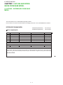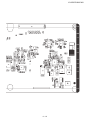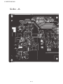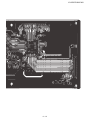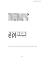
1
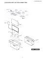
TopPage
1st Addition
SERVICE MANUAL
No.S13M1460LE631MX-WH
LCD COLOUR TELEVISION
MODEL :LC-60LE631M-WH
LC-60LE631X-WH
In the interests of user-safety (Required by safety regulations in some countries) the set should be restored to its original condition and only parts identical to those specified should be used.
CONTENTS
CHAPTER 1.OUTLINE AND DIFFERENCES
FROM BASE MODEL
OUTLINE/
DIFFERENCES FROM BASE MODEL ...1
SAFETY PRECAUTION
IMPORTANT SERVICE SAFETY
PRECAUTION.......................................1-2
PRECAUTION FOR USING LEED-FREE
SOLDER...............................................1-3
[2] MAJOR SERVICE PARTS
MAJOR SERVICE PARTS......................1-4
CHAPTER 2. SPECIFICATIONS
[1] SPECIFICATION.................................2-1
CHAPTER 3.OPERATION MANUAL
[1] OPERATION MANUAL........................3-1
CHAPTER 4.DIMENSIONS
[1] DIMENSIONS
............................. .. 4-1
CHAPTER 5. REMOVING OF MAJOR PARTS
[1] REMOVING OF MAJOR PARTS...........5-1
CHAPTER 6. TROUBLESHOOTING TABLE
[1] TROUBLESHOOTING TABLE .........................6-1
CHAPTER 7. OVERALL WIRING/BLOCK DIAGRAM
[1] OVERALL WIRING DIAGRAM ............................7-1
[2] SYSTEM BLOCK DIAGRAM............................ 7-2
CHAPTER 8. PRINTED WIRING BOARD ASSEMBLIES
[1] Main Unit ...................................................8-1
[2] T-CON Unit ..............................................8-9
[3] RC/LED Unit ......................................... ..8-13
[4] KEY Unit ...................................................8-15
CHAPTER 9. SCHEMATIC DIAGRAM
[1] DESCRIPTION OF SCHEMATIC
DIAGRAM..................................................9-1
[2] MAIN Unit.. ...............................................9-2
[3] T-CON Unit. .............................................9-5
[4] RC/LED Unit ............................................9-15
[5] KEY Unit ...................................................9-17
Parts Guide
Parts marked with "
" are important for maintaining the safety of the set. Be sure to replace these parts with specified ones for maintaining the
safety and performance of the set.
This document has been published to be used for
after sales service only.
The contents are subject to change without notice.
LC-60LE631M/X-WH
CHAPTER 1. OUTLINE AND DIFFERENCES FROM BASE MODEL
[1] OUTLINE / DIFFERENCES FROM BASE
MODEL
This model is based on the LC-60LE630M/X and partially modified.
For the contents not covered in this Service Manual, accordingly, please refer to the LC-60LE630M/X Service Manual
DIFFERENCES FROM BASE MODEL
LIST OF CHANGED PARTS
KEYMF904FM10 (60LE631M-WH)
Part code changed
KEYMF904FM12 (60LE631X-WH)
Part code changed
Ref. No.
Description
LC-60LE630M/X
PRINTED WIRING BOARD ASSEMBLIES
N
MAIN Unit
DKEYMF904FMG1
N
MAIN Unit
DKEYMF904FMG2
N
R/C LED Unit
RUNTKF799FMF7
N
KEY Unit
DUNTKF800FMF7
N
POWER Unit
RUNTKA847WJN1
N
T-CON
DUNTKF908FM06
DKEYMF904FM10
DKEYMF904FM12
DUNTKG016FMF8
DUNTKF800FMF8
RUNTKB057WJQZ
DUNTKF908FM11
Part code changed
Part code changed
Changed
Changed
Changed
Changed
LCD PANEL
N
LCD Panel Module Unit
R1LK600D3GV0DF
Changed
R1LK600D3GW8BW
LC-60LE631M/X-WH
Note
CABINET PARTS, SUPPLIED ACCESSORIES, PACKING PARTS (NOT REPLACEMENT ITEM), SERVICE JIGS (USE FOR SERVICING)
Please refer to a Parts list.
1–1
LC-60LE631M/X-WH
SAFETY PRECAUTIONSAFETY PRECAUTIONSAFETY PRECAUTIONSAFETY PRECAUTIONSAFETY PRECAUTIONSAFETY PRECAUTIONSAFETY PRECAUTIONSAFETY PRECAUTIONSAFETY PRECAUTIONSAFETY PRECAUTIONSAFETY PRECAUTIONSAFETY
LC32LE240M
5GTXKEG/CPWCN
IMPORTANT SERVICE SAFETY PRECAUTION
Service work should be performed only by qualified service technicians who are thoroughly familiar with all safety checks and the
servicing guidelines which follow:
WARNING
All checks must be repeated with the AC cord plug connection
reversed. (If necessary, a nonpolarized adaptor plug must be used
only for the purpose of completing these checks.)
1. For continued safety, no modification of any circuit should be
attempted.
Any reading of 0.74 Vrms (this corresponds to 0.5 mA rms AC.) or
more is excessive and indicates a potential shock hazard which
must be corrected before returning the monitor to the owner.
2. Disconnect AC power before servicing.
BEFORE RETURNING THE RECEIVER (Fire &
Shock Hazard)
Before returning the receiver to the user, perform the following
safety checks:
DVM
AC SCALE
3. Inspect all lead dress to make certain that leads are not pinched,
and check that hardware is not lodged between the chassis and
other metal parts in the receiver.
1.5k ohm
10W
4. Inspect all protective devices such as non-metallic control knobs,
insulation materials, cabinet backs, adjustment and compartment
covers or shields, isolation resistor-capacitor networks, mechanical
insulators, etc.
5. To be sure that no shock hazard exists, check for leakage current in
the following manner.
•
Plug the AC cord directly into a 110-240 volt AC outlet.
•
Using two clip leads, connect a 1.5k ohm, 10 watt resistor paralleled by a 0.15 F capacitor in series with all exposed metal cabinet
parts and a known earth ground, such as electrical conduit or electrical ground connected to an earth ground.
•
Use an AC voltmeter having with 5000 ohm per volt, or higher, sensitivity or measure the AC voltage drop across the resistor.
•
Connect the resistor connection to all exposed metal parts having a
return to the chassis (antenna, metal cabinet, screw heads, knobs
and control shafts, escutcheon, etc.) and measure the AC voltage
drop across the resistor.
0.15 µF
TEST PROBE
TO EXPOSED
METAL PARTS
CONNECT TO
KNOWN EARTH
GROUND
///////////////////////////////////////////////////////////////////////////////////////////////////////////////////////////////////////////////////////////////////////////////////////////////////////////////////////////////////////////
SAFETY NOTICE
Many electrical and mechanical parts in LCD colour television have
special safety-related characteristics.
For continued protection, replacement parts must be identical to those
used in the original circuit.
These characteristics are often not evident from visual inspection, nor
can protection afforded by them be necessarily increased by using
replacement components rated for higher voltage, wattage, etc.
The use of a substitute replacement parts which do not have the same
safety characteristics as the factory recommended replacement parts
shown in this service manual, may create shock, fire or other hazards.
Replacement parts which have these special safety characteristics are
identified in this manual; electrical components having such features
are identified by " " and shaded areas in the Replacement Parts List
and Schematic Diagrams.
///////////////////////////////////////////////////////////////////////////////////////////////////////////////////////////////////////////////////////////////////////////////////////////////////////////////////////////////////////////
PRECAUTIONSAFETY PRECAUTIONSAFETY PRECAUTIONSAFETY PRECAUTIONSAFETY PRECAUTION
1–2
LC-60LE631M/X-WH
PRECAUTIONS FOR USING LEAD-FREE SOLDER
Employing lead-free solder
• “PWBs” of this model employs lead-free solder. The LF symbol indicates lead-free solder, and is attached on the PWBs and service manuals. The
alphabetical character following LF shows the type of lead-free solder.
Example:
Indicates lead-free solder of tin, silver and copper.
Indicates lead-free solder of tin, silver and copper.
Using lead-free wire solder
• When fixing the PWB soldered with the lead-free solder, apply lead-free wire solder. Repairing with conventional lead wire solder may cause damage or accident due to cracks.
As the melting point of lead-free solder (Sn-Ag-Cu) is higher than the lead wire solder by 40 C, we recommend you to use a dedicated soldering
bit, if you are not familiar with how to obtain lead-free wire solder or soldering bit, contact our service station or service branch in your area.
Soldering
• As the melting point of lead-free solder (Sn-Ag-Cu) is about 220 C which is higher than the conventional lead solder by 40 C, and as it has poor
solder wettability, you may be apt to keep the soldering bit in contact with the PWB for extended period of time. However, Since the land may be
peeled off or the maximum heat-resistance temperature of parts may be exceeded, remove the bit from the PWB as soon as you confirm the
steady soldering condition.
Lead-free solder contains more tin, and the end of the soldering bit may be easily corroded. Make sure to turn on and off the power of the bit as
required.
If a different type of solder stays on the tip of the soldering bit, it is alloyed with lead-free solder. Clean the bit after every use of it.
When the tip of the soldering bit is blackened during use, file it with steel wool or fine sandpaper.
• Be careful when replacing parts with polarity indication on the PWB silk.
Lead-free wire solder for servicing
PARTS CODE
ZHNDAi123250E
ZHNDAi126500E
ZHNDAi12801KE
PRICE
RANK
BL
BK
BM
PART
DELIVERY
J
J
J
DESCRIPTION
0.3mm 250g (1roll)
0.6mm 500g (1roll)
1.0mm 1kg (1roll)
1–3
LC-60LE631M/X-WH
[2] MAJOR SERVICE PARTS
MAJOR SERVICE PARTS
LC60LE630M
MAJOR SERVICE PARTS
PWB UNIT
Ref No.
N
N
N
N
N
N
Part No.
DKEYMF904FM10
DKEYMF904FM12
DUNTKG016FMF8
DUNTKF800FMF8
RUNTKB057WJQZ
DUNTKF908FM11
Description
MAIN Unit (LC-60LE631M-WH)
MAIN Unit (LC-60LE631X-WH)
R/C LED Unit
KEY Unit
POWER Unit
T-CON Unit
OTHER UNIT
Ref No.
Part No.
N
R1LK600D3GV0DF
Description
60" LCD Panel Module Unit
SERVICE JIGS
Ref No.
Part No.
N
N
N
N
QCNW-C222WJQZ
QCNW-F676WJQZ
QCNW-G405WJQZ
QCNW-N125WJPZ
CNW-
Description
Connecting Cord,T-Con - LCD Panel
Connecting Cord, Main-T-Con (LW)
Connecting Cord, Main-T-Con (PL)
Connecting Cord, Main-Power (PD)
1–4
Q’ty
2
1
1
1
LC-60LE631M/X-WH
CHAPTER 2. SPECIFICATIONS
[1] SPECIFICATIONS
Model LC-60LE631M-WH / LC-60LE631X-WH
Item
60" (1525 mm) Active Matrix type a - Si TFT
LCD panel
Resolution
Video Colour System
TV
TV-Standard ( 60LE631M-WH )
Function TV-Standard Analogue
(60LE631X-WH) Digital
Receiving
VHF/UHF
Channel
CATV
TV-Tuning System
STEREO/BILINGUAL
Viewing angles
Audio amplifier
Speakers
Terminals
2,073,600 pixels (1920 x 1080)
PAL/SECAM/NTSC 3.58/NTSC 4.43/PAL 60
PAL: B/G, D/K, I SECAM: B/G, D/K, K/K1 NTSC: M
PAL: B/G, D/K, I SECAM: B/G, D/K, K/K1
DVB-T
44.25 — 863.25 MHz
S1 — S41ch (including Hyperband)
Auto Preset 99 ch
NICAM: B/G, I, D/K A2 stereo: B/G
H : 176º V : 176º
10 W x 2
3.2 x 15 cm 2pcs
Antenna input
HDMI 1
HDMI 2
HDMI 3
INPUT 4
INPUT 5
INPUT 6
UHF/VHF 75 DIN type
HDMI (HDMI input) (480I, 576I, 480P, 576P, 720P/50Hz, 720P/60Hz, 1080I/50Hz,
1080I/60Hz, 1080P/50Hz, 1080P/60Hz, 1080P/24Hz), AUDIO in (common use with
PC) (Ø 3.5 mm jack)
HDMI (HDMI input) (480I, 576I, 480P, 576P, 720P/50Hz, 720P/60Hz, 1080I/50Hz,
1080I/60Hz, 1080P/50Hz, 1080P/60Hz, 1080P/24Hz)
VIDEO in, AUDIO in
VIDEO in, AUDIO in
AUDIO in, COMPONENT in (480I, 576I, 480P, 576P, 720P/50Hz, 720P/60Hz,
1080I/50Hz, 1080I/60Hz)
AUDIO OUT
Audio out
AUDIO IN (R/L)
Ø 3.5 mm jack*
PC
15 pin mini D-sub, AUDIO in (common use with HDMI 1) (Ø 3.5 mm jack)
USB
USB
RS-232C
9 pin D-sub male connector
DIGITAL AUDIO OUTPUT Optical Digital Audio Output
Headphones
Ø 3.5 mm jack
OSD language (60LE631M-WH) English/Simplified Chinese/Arabic/French/Portuguese/Russian/Persian/Thai/
Vietnamese/Indonesian
OSD language (60LE631X-WH) English
Power Requirement
AC 110 — 240 V, 50/60 Hz
Power Consumption
188 W (0.5 W Standby)
without stand (mm) 1384 (W) x 839 (H) x 73 (D)
Dimensions
with stand (mm)
1384 (W) x 874 (H) x 341.5 (D)
Weight without stand (with stand) 25.5 kg (28.5 kg)
Operating Temperature
0°C — 40°C
* The HDMI1 and PC terminals can both use the same audio input terminal.
As a part of policy of continuous improvement, SHARP reserves the right to make design and specification changes for
product improvement without prior notice. The performance specification figures indicated are nominal values of production
units. There may be some deviations from these values in individual units.
2–1
LC-60LE631M/X-WH
CHAPTER 3. OPERATION MANUAL
[1] OPERATION MANUAL
4
Attaching the stand unit
Attaching the s tand cover.
1
2
Before performing work, spread cushioning over the surface
on which you will be laying the TV. This will prevent it from
being damaged.
Insert the stand cover.
Insert and tighten four short screws into the holes of
the stand cover.
CAUTION
Attach the stand in the correct direction.
Be sure to follow the instructions. Incorrect installation
of the stand may result in the TV falling over.
1
C onfirm that there are s crews with the s tand unit.
(Eight long screws and four short screws)
2
Attach the s upporting pos t for the s tand unit onto
the bas e us ing the long s crews with a s crewdriver
as s hown.
Supporting
post
Front
3
Ins ert the s tand into the openings on the bottom
of the TV (hold the s tand s o it will not drop from
the edge of the bas e area).
Soft cushion
3–1
NOTE
To detach the stand unit, perform the steps in reverse order.
A screwdriver is not supplied with this product.
LC-60LE631M/X-WH
CHAPTER 4. DIMENSIONS
[1] DIMENSIONS
Dimensional drawings
Unit: mm
1384
1333*1
1333
*1
341.5
400
386
438
178
10 ο
106
219
AN-52AG4
I
Active area
NOTE
• Dimensions do not include protrusions such as screws and some parts.
4–1
LC-60LE631M/X-WH
CHAPTER 5. REMOVING OF MAJOR
PARTS
JOR
PAR
TRE
MO
VIN
[1] REMOVING OF MAJOR PARTS
G
OF
MAJ
OR
PAR
TRE
MO
1. Removing of the Stand Unit and Rear Cabinet
VIN
G
OF
1. Remove the 4 lock screws [1] and detach the Stand Unit [2].
MAJ
OR
PAR
TRE
2. Remove the 1 lock screw [3] and detach the AC Cord Cover [4].
MO
VIN
G
3. Disconnect AC Cord [5].
OF
MAJ
OR
4. Remove the 16 lock screws [6], 1 lock screw [7], 3 lock screws [8], 2 lock screw [9],
PAR
TRE
MO
VIN
5. Remove the 10 lock screws [10], and detach the Rear Cabinet A ss’y [11].
G
OF
MAJ
OR
PAR
TRE
MO
VIN
G
OF
MAJ
OR
PAR
TRE
6
MO
VIN
G
OF
11
MAJ
OR
PAR
TRE
MO
VIN
G
OF
MAJ
OR
PAR
TRE
MO
VIN
G
OF
MAJ
OR
PAR
TRE
MO
VIN
G
OF
MAJ
OR
PAR
TRE
MO
VIN
G
OF
5
MAJ
OR
PAR
4
T
8
7
3
9
9
10
1
2
5–1
LC-60LE631M/X-WH
2. Removing of Connectors
1. Disconnect the following connectors from the MAIN Unit. (PD, LW, PL, RA)
2. Disconnect the following connectors from the POWER Unit. ( PD )
3. Disconnect the following connectors from the LCD CONTROL Unit. (LW, PL, FFC)
4. Disconnect the following connectors from the KEY Unit. (KM)
5. Disconnect the following connectors from the R/C, LED Unit. (RA)
5–2
LC-60LE631M/X-WH
3. R emoving of S peaker (L/R)
1. R emove the 4 Hooks and detach the 2 Bottom Cover (8) .
2. Detach the S peake r (L) (1) , S pea ker (R) (2) .
5–3
LC-60LE631M/X-WH
4. Removing of the PWB Units
1. Detach the Key Cover [1], remove the 2 lock screws [2], detach the Key Button [3] and detach the KEY Unit [4].
2. Detach the R/C LED Unit [5].
3. Detach the Side Cover [6].
4. Remove the 2 lock hexagon screws [7] and 2 lock hexagon screws [8].
5. Remove the 10 lock screws [9] and detach the MAIN Unit [10] and POWER Unit [11].
6. Remove the 6 lock screws [12] and detach the LCD CONTROL Unit [13].
10
7
9
Side Cover
6
8
MAIN Unit 10
POWER Unit 11
Key Button
3
2
KEY Unit
4
KEY Cover
1
R/C LED Unit 5
12
LCD CONTROL Unit 13
5–4
LC-60LE631M/X-WH
5. Removing of the LCD Panel Module Unit
1. Detach the 21 H ooks [1] and detach the LCD Panel Module Unit [2].
1
5–5
LC-60LE631M/X-WH
[ 2 ] PRECAUTIONS FOR ASSEMBLY
[Precautions when fixing the Rear Cabinet]
When fixing the Rear Cabinet, be careful not to catch the backlight LED harness, speaker harness and other harnesses in it.
•
The hooks on the external wall of the Rear Cabinet are fitted in the Front Cabinet Ass’y. After putting the Rear Cabinet in place, fit the hooks
securely; then tighten the screws.
(Work method of Rear Cabinet fixation)
Rear Cabinet
(Mat parts)
Front Cabinet Ass'y
(Luster parts)
There is a gap without the fingernail fitting in completely only when covering
with Rear Cabinet.
It becomes the factor of a gap increase of Front Cabinet Ass'y/Rear Cabinet
and the Rear Cabinet misregistration.
Please tighten the screw after Rear Cabinet is firmly pushed, and the
fingernail is confirmed.
(Front Cabinet Ass’y/Rear Cabinet fingernail fixation place)
5–6
LC-60LE631M/X-WH
[3] THE way of detaching Rear Cabinet
[Precaution when removing the rear cabinet]
If the rear cabinet is removed with the set upright, the speakers may fall; it results in connector disconnection. Therefore, never remove the rear cabinet with the set upright.
Be sure to remove the rear cabinet with the screen side down.
Screws for fixing Speaker
and Rear Cabinet
Speaker fall down.
Speaker incline.
[Precaution when mounting the rear cabinet]
Put the speakers in place with the screen side down, and attach the rear cabinet.
Since the speakers are fixed by the rear cabinet, they cannot be fixed without the rear cabinet.
5–7
LC-60LE631M/X-WH
CHAPTER 6. TROUBLESHOOTING
TABLE
[1] TROUBLESHOOTING TABLE
No power (front LED failure to light up) or no startup (front LED failure to turn from red to green)
Is the AC cord plug tightly connected to the set?
NO
Reconnect the AC cord tightly and turn on the power again.
NO
Replace the power unit.
YES
Are the wire harnesses and other cables properly connected in
the set?
NO
Reconnect the wire harnesses and other cables properly in the
set.
YES
Is there the AC_DET and PNL_ON signal input at pins (11) and
(10) of P9601?
NO
Check the AC_DET signal line PNL_ON signal line.
YES
Are the DC/DC converter outputs and the output voltages along
the control lines as specified?
NO
Check the DC/DC converters and the control lines. Replace
defective parts as required.
YES
Is the output voltage at pin (9) of P9601 (BU+5V line) as specified?
Is the output voltage at pin (17), (18), (19) and (20) of P9601
(13V line) as specified?
1)
2)
3)
4)
5)
6)
7)
8)
B1.26V (IC9604)
B5.6V (IC9602)
BU3.3V (IC9601)
D3.3V (IC9606)
B5V (IC9611)
B1.8V (IC9610)
AU3.3V (IC9603)
AU1.8V (IC9607)
With [RF] signal input
No video onscreen (1)
No video in the UHF/VHF reception
Is there IF output from the tuner pin(12) of TU1103 as specified?
Is there VIDEO output from the tuner pin(16) of TU1103 as specified?
YES
Is there VIDEO input at pin (M3) of IC3303?
YES
Are there the signal outputs at pin AC (21), (22), (23), (24), AD
(21), (22), (23), (24) and AE (21), (22), (23), (24) of IC3303?
NO
Check TU1103 and its peripheral circuits.
NO
Check the circuit between TU1103 & IC3303.
NO
Check IC3303 and its peripheral circuit.
YES
Check LVDS cable, LCD controller (incl. panel) and their peripheral circuits.
6–1
LC-60LE631M/X-WH
No audio heard (1)
No sound in the UHF/VHF reception.
Is the IF output from the tuner pin (13) of TU1103 as specified?
NO
Check TU1103 and its peripheral circuits.
YES
Is there the signal input at pins (W3) of IC3303?
NO
Check IC3303 and its peripheral circuits.
YES
Is there I2S_LRCLK signal input at pin(9) of IC2707?
NO
Check connection between IC3303 and IC2707 and its
peripheral circuits.
YES
Is there AMP_LRCLK signal input at pin(8) of IC2704?
NO
Check connection between IC2707 and IC2704 and its
peripheral circuits.
YES
Is the L-ch audio signal output at pin(28) and (30) of IC2704 normal?
Is the R-ch audio signal output at pin(12) and (14) of IC2704 normal?
NO
Check IC2704 and its peripheral circuits.
YES
Are the audio signal L-ch and R-ch output at (4)/(5) and (1)/(3) of
P2702 normal?
NO
Check circuit between IC2704 & P2702.
YES
Check speakers and their peripheral circuits.
6–2
LC-60LE631M/X-WH
No audio heard (2)
No external audio heard
<INPUT 4>
Is there the L-ch audio signal input from pin (15) of input terminal
J504 to pin (AE2) of IC3303?
Is there the R-ch audio signal input from pin (8) of input terminal
J504 to pin (AE3) of IC3303?
<INPUT 5>
Is there the L-ch audio signal input from pin (16) of input terminal
J504 to pin (AB1) of IC3303?
Is there the R-ch audio signal input from pin (10) of input terminal
J504 to pin (AA1) of IC3303?
<INPUT 6>
Is there the L-ch audio signal input from pin (2) of input terminal
J503 to pin (Y1) of IC3303?
Is there the R-ch audio signal input from pin (4) of input terminal
J503 to pin (AA3) of IC3303?
YES
Is there the I2S signal output at pin A8, C7, B7 and D8 of IC3303?
NO
Check IC3303 and its peripheral circuits.
YES
Is there I2S_LRCLK signal input at pin(9) of IC2707?
NO
Check connection between IC3303 and IC2707 and its peripheral circuits.
YES
Is there AMP_LRCLK signal input at pin(8) of IC2704?
NO
Check connection between IC2707 and IC2704 and its peripheral circuits.
NO
Check IC2704 and its peripheral circuits.
NO
Check circuit between IC2704 & P2702.
YES
Is the L-ch audio signal output at pin(28) and (30) of IC2704 normal?
Is the R-ch audio signal output at pin(12) and (14) of IC2704 normal?
YES
Are the audio signal L-ch and R-ch output at (4)/(5) and (1)/(3) of
P2702 normal?
YES
Check speakers and their peripheral circuits.
6–3
LC-60LE631M/X-WH
No audio heard (3)
No HDMI sound heard. HDMI1
(*INPUT 1 is digital audio.)
Does the HDMI image appear onscreen?
NO
Refer to “HDMI1 in No external input video onscreen (HDMI)”.
NO
Check the EDID.
NO
Check peripheral circuits of IC3303.
YES
Is there I2S_LRCLK signal input at pin(9) of IC2707?
NO
Check connection between IC3303 and IC2707 and its peripheral circuits.
YES
Is there AMP_LRCLK signal input at pin(8) of IC2704?
NO
Check connection between IC2707 and IC2704 and its peripheral circuits.
NO
Check IC2704 and its peripheral circuits.
NO
Check circuit between IC2704 & P2702.
YES
No audio output from HDMI1.
YES
Are waveforms input in to the pin F1, F2, G1, G2, G3, H1, H2 and
H3 of IC3303 normally and I2S output normally?
Are waveforms input in to the pin A8, C7, B7 and D8 of IC3303
normally and I2S output normally?
YES
Is the L-ch audio signal output at pin (28) and (30) of IC2704 normal?
Is the R-ch audio signal output at pin (12) and (14) of IC2704 normal?
YES
Are the audio signal L-ch and R-ch output at (4)/(5) and (1)/(3) of
P2702 normal?
YES
Check speakers and their peripheral circuits.
6–4
LC-60LE631M/X-WH
No audio heard (4)
No sound from the HDMI sound input terminal.
(HDMI1 analog audio)
YES
Is there the L-ch audio signal input from pin (2) of external input
terminal J506 (HDMI AUDIO IN) to pin (AC2) of IC3303?
Is there the R-ch audio signal input from pin (3) of external input
terminal J506 (HDMI AUDIO IN) to pin (AB2) of IC3303?
YES
Are I2S signal output at pin A8, C7, B7 and D8 of IC3303 normally?
NO
Check peripheral circuits of IC3303.
YES
Is there I2S_LRCLK signal input at pin(9) of IC2707?
NO
Check connection between IC3303 and IC2707 and its peripheral circuits.
YES
Is there AMP_LRCLK signal input at pin(8) of IC2704?
NO
Check connection between IC2707 and IC2704 and its peripheral circuits.
NO
Check IC2704 and its peripheral circuits.
NO
Check circuit between IC2704 & P2702.
YES
Is the L-ch audio signal output at pin(28) and (30) of IC2704 normal?
Is the R-ch audio signal output at pin(12) and (14) of IC2704 normal?
YES
Are the audio signal L-ch and R-ch output at (4)/(5) and (1)/(3) of
P2702 normal?
YES
Check speakers and their peripheral circuits.
6–5
LC-60LE631M/X-WH
No audio heard (5)
No PC audio output
YES
Pin (2) of J506: Is L-ch input into the pin (AC2) of IC3303?
Pin (3) of J506: Is R-ch input into the pin (AB2) of IC3303?
YES
Are I2S signal output at pin A8, C7, B7 and D8 of IC3303 normally?
NO
Check peripheral circuits of IC3303.
YES
Is there I2S_LRCLK signal input at pin(9) of IC2707?
NO
Check connection between IC3303 and IC2707 and its
peripheral circuits.
YES
Is there AMP_LRCLK signal input at pin(8) of IC2704?
NO
Check connection between IC2707 and IC2704 and its
peripheral circuits.
YES
Is the L-ch audio signal output at pin(28) and (30) of IC2704 normal?
Is the R-ch audio signal output at pin(12) and (14) of IC2704 normal?
NO
Check IC2704 and its peripheral circuits.
YES
Are the audio signal L-ch and R-ch output at (4)/(5) and (1)/(3) of
P2702 normal?
NO
Check circuit between IC2704 & P2702.
YES
Check speakers and their peripheral circuits.
6–6
LC-60LE631M/X-WH
CHAPTER 7. OVERALL
WIRING
/
BLOCK DIAGRAM
[1] SYSTEM BLOCK DIAGRAM
[2] SYSTEM BLOCK DIAGRAM
1. LC-60LE631M-WH
Q96
7–1
LC-60LE631M/X-WH
Right-Audio-Left
+B1
Audio
Out
VIDEO
Right-Audio-Left
INPUT 4
VIDEO INPUT5
Right-Audio-Left
INPUT6
Right-Audio-Left
HDMI2_
HDMI2_SDA/SC
Input 3
HDMI3
HDMI1_SDA/SCL
HDMI1
Input 2
HDMI2
HDMI0_SDA/SCL
HDMI0_
H/P
L/R
SPI_CK
SPI_DI
SPI_CZ
SPI_DO
SPI_WP
B1.26V
Q9602
D3.3V
UART_RX/TX
Input 1
HDMI1
INPUT7
PC_R/G/B
USB
D3.3V
IC9610
S172B18U
B1.26V
B1.8V
R/L
H/P
Input 7
Digital
Audio Out
B9V
Audio Input
Audio R/L
7–2
LC-60LE631M/X-WH
2. LC-60LE631X-WH
Q960
7–3
LC-60LE631M/X-WH
Right-Audio-Left
VIDEO
INPUT 4
ANT +5V
+B1
Audio
Out
Right-Audio-Left
VIDEO INPUT5
Right-Audio-Left
INPUT6
Right-Audio-Left
D3.3V
HDMI2_
B1.2V
HDMI2_SDA/SC
Input 3
HDMI3
HDMI1_SDA/SCL
HDMI1
Input 2
HDMI2
HDMI0_SDA/SCL
HDMI0_
D3.3V
H/P
L/R
Q9602
SPI_CK
SPI_DI
SPI_CZ
SPI_DO
SPI_WP
B1.26V
UART_RX/TX
Input 1
HDMI1
INPUT7
PC_R/G/B
USB
D3.3V
IC9610
S172B18U
B1.26V
B1.8V
R/L
H/P
Input 7
Digital
Audio Out
B9V
Audio Input
Audio R/L
7–4
LC-60LE631M/X-WH
[2] OVERALL WIRING DIAGRAM
[1] OVERALL WIRING DIAGRAM
to LED m
power RUNTKB057
[AC]
Key DUNTKF800FMF8
control(Guava)
Control DUNTKF908WE
SP-R RSP-ZA577WJZZ
7–5
[F
QCNW-N079WJQZ
LC-60LE631M/X-WH
ED module
QCNW-N110WJPZ
main DUNTKF904FM10
DUNTKF904FM12
[PD]
QCNWM140WJQZ
[PL]
60LE631M
60LE631X
[PD]
B057WJQZ
HDMI
1
Tuner
[LW]
HDMI
2
USB
HDMI
3
[SP]
[RA]
QCNWN111WJPZ
QCNWN113WJPZ
[PL]
08WE11
[LW]
QCNWN112WJQZ
[FFC]
SP-L RSP-ZA576WJZZ
R/C DUNTKG016FMF8
7–6
10
P2703
L2704
R2785
R2786 R2788
R2767
C2746 R2787
R2782
R2779
R2778
R2765
R2777 R2764
D2707
C2740
D2705
R2793
FB2709
D2704
TP2706
R2763
L2703
C2744
FB2704
FB2703
R2790
C2749
C2727
C2730
C2729
D2709
C2751
C2754
C2755
C2752
Q2706
R2754
R2753
R2752
R2750
C504
R502
D502
L2706
C2702
C501
R508 C502
Q501
Q503
D504
C2720
C2722
C2728
Q1504
Q1501
C2731
IC2707
IC2702
R2736
R2737
R2731
SG1522
SG1516
TP2705
C9606
SG1507
SG1504
R2746
R2795
R2796
SG1513
SG1510
SC1501
SG1519
TP2703
C2741
IC3501
D2708
L2702
R2794
C2738
C2743
C3501
R3522
SG1501
R3388
R3524
R3514
R3444
R3442
R3515
R3516
R3508
R3513
R3443
R3384
R3521
R3511
R3509
R3523
R3510
R3507
R3503 R3504
R3502 R3506
R3505
R3512
R3416 R3413
R3415
R3414
Q1503
R1513
R1516
R3528
R3546
R3552
IC3502
SG1524
RDA3301
SG1515
SG1512
SC1503
SG1521
SG1518
R3398
R3397
R3399
R3400
R3403
R3404
C2773
C2775
C2774
FB2711
FB2710
P2702
R3544
SG1509
SG1506
SG1503
R3380
R3545
R3551
R3547
R3548
R3445
R3537
FB2712
C2736
C2733
C2742
C2737
IC2704
C2734
C2735
D2706
C3330
R3423
R3411
R3410
R3409
R3406
R3405
R3347 R3346
R3358
R3359
L2604
L2601
C3301
R3301
L2605
L2602
L2603
R3364 R3363
R3365
C8404
L2606
SC2601
C2709
Q2701
R2724 C2712 C2704
R2708
R2723 R2719
R2712
R2721
IC2703
R2722 R2720 C2705
R2725 C2711
IC8404
R2607
R2603
R2629
R2625
R2608
C2602
C2707
L2705
C2747
L2701
X2701
R2701
R2789
C2753
C2776
C2756
FB505
C505
R2704
C2771
FB2701
FB2702
C2701
R2711
R2716
R2707
R2705
R2703
R2804
R2801
C2719
P2701
D1502
D1514
R1511
R3381
TP2704
R2748
R2749
R2742
R2741
R2740
TP2701
R2730
TP2702
C2724
C2725
R2747
R2751
R3519
R3520
R3518
R3501
R9677
R2760
R2771
R2761
R2762
R2772
R2773
R2774
R2783
R2784
R2776
R2759
X3301
R3527
C9637
R2744
R3517
R3382
C3349
C3350
IC3301
R3531
R3534
R3395
R3543
R3542
R3378
R3341
R3342
D1504
D1516
R3529
R3530
R3532
R3533
R3389
R3390
R3539
IC3303
C3302
R3352
R3396
R3540
R3535
R3536
R3441
R3440
R2717
R2729
R2732
R1514
R1508
9
Q1506
8
R1510
C3319
R3314
R3430
R3538
R3541
C3332
R2611
C2610
R2626
IC2603
R1507
C9633
C9646
C9645
R9627 C9622
D9602
L9601
C9616
SC1502
SG1514
SG1502
SG1517
SG1505
SG1523
SG1511
SG1520
SG1508
R9648
R9609
R9634
R9630 R9624
C9625
C9619
R9619
FB9603
IC9604
D9604
L9603
R9612
Q9601
C1111
C1108
D1101
Q9605
R1130
R9680
R9602
R9679
FB9606
R9678
R9625
R9641
FB9608
C2611
P2601
R9643
C9629
R9655
IC1105
IC9606
L9602
R9642
C9632
C2739
R3429
R3549
R3550
C3318
C3320
C3307
C3317
C3308
C3419
R3313
R3315
R3302
R3312
R3303
R3428
C3312
R3307
C3314
R3333
C3306
R3323
R3332
C3331
R3367
R8401
R3379
R3351
R3354
R3355
R3331
R3383
R3366
C2757
R2727
C2792
C2758
R2728
C2791
C3337
R3327
C3329
C2710
R2601
R2602
R2709
R2628
R2627
C9631
C9630
IC9602
C9628
C9610
C9618
R9670
R9671
D9610
D9601
R9601
C9647
C2601
R2718
R2713
R2726
7
R1105
C1114
8–1
C9626
6
R9651
5
L1104
4
R1116
R1110
3
P9601
C9634
2
R9656
R9649
1
C1144
R1153
A
C1145
B
FB1104
C
C1107
D
IC1101
E
R9610
F
C9620
C1109
C1113
R1128
R1129
C1118
C1121
R1131
IC1102
C1147
C9617
G
C9623
R9614
C9601
CHAPTER 8. PRINTED
R1111
R1117
R1123
C2732
LC-60LE631M/X-WH
WIRING
BOARD ASSEMBLIES
[1] MAIN Unit
Chip Parts Side -A
H
VA513
SC501
R3324
C3343
TH3301
C524
C523
Q2703
R2781
D516
R2768
FB505
C505
FB504
D503
C507
FB506
C504
R502
C501
R3374
R545 R537 R529
R546 R538 R530
VA527 VA521 VA517
R508 C502
Q501
R503
C506
R509
D501
C2761
R2810
Q503
FB3322
P3301
R3452
J503
FB529
R549
SG1522
SG1510
FB527
R547
SG1507
R3372
C3365
R3362
R3371
C3368
J509
J504
FB528
R548
SC1501
SG1519
VA532
FB3315
C3369
VA3305
D502
FB3319
R532
R527
C527
R528
VA516
R515
J505
R525
C526
R526
VA515
R540
R633
SG1524
C553
R590
R577 C548
C544 R581
R578
R614
FB515
R541
SG1512
SC1503
SG1521
FB507
R501
IC508
R625
FB512
R533
VA525
J502
R524
C531 C533 C518 C539 C537
R534 R536 R516 R544 R542
C530 C532 C517 C538 C536
FB513 FB514 FB509 FB524 FB516
VA519 VA520 VA510 VA526 VA523
Q1503
FB501
IC501
R3424
R3361
R3336
R3451
FB3321
FB3318
FB3310
FB3320
VA531
C3367
R3373
FB3307
R1
FB502
C565
C566
R616
D510
VA522
C543
VA524
FB520
D513
J501
FB503
C549
VA528
R632 R630
R631 R593
SG1509
D512
R613
R610 FB519
R621
C561
R611 VA504
R620
C560
VA503
J506
C516
C510
L501
C550
VA529
C509
R511
R507 R505 C515
R510 R506 R513
C511 C508
C514
FB526 FB525 FB508
VA508 VA507 VA509
IC503
C551
VA530
R512
SG1523
SG1505
SG1511
SG1508
SC1502
SG1520
D1101
C1111
C1108
R1116
R1110
C1117
R1112
R1114
R1130
R1136
R1132
R1138
R1139
L1102
C1142
IC1104
C1143
C1130
L1103
C1123 R1125
C1125
Q1104
C1120
R1121
R1115
R1118
R1
VA533
FB3323
FB3324
R3322
R3321
R3453
FB3325
17
FB3316
VA3304
FB3317
VA3303
C512
FB521
R582
SC502
FB522
R583
VA505
VA518
VA514
C525
R523
16
VA506
FB523
R1105
C1114
R1124
R1150
R1122
C1115
Q
R584
15
C513
R514
8–2
L1101
14
C1138
IC1103
13
D1102
C1107
R1144
C1128
C1140
IC1101
C1127
C1126
R1146
R1145
C1141
R1149
R1148
C1133
C1132
Q1102
C1122
12
R1104
11
R1120
R1111
R1117
R1123
C1136
C1135
10
C1109
C1113
R1128
R1129
C1118
C1121
R1131
R1137
X1101
R1147
FB1102
C1139
C1129
C1134
R1143
R1142
D504
LC-60LE631M/X-WH
18
19
TU1101
TU1103
R543
R535
LC-60LE631M/X-WH
Side -A
H
G
F
E
D
C
B
A
1
2
3
4
6
5
8–3
7
8
9
10
LC-60LE631M/X-WH
10
11
12
13
14
15
8–4
16
17
18
19
LC-60LE631M/X-WH
Chip Part Side - B
H
TL1114
FB1103
C1116
R1141
C1137
R1126
C1148
C1149
TL1139
TL1136
TL1134
TL1123
TL1121
TL1138
TL1137
TL1135
TL1133
TL1132
TL1131
TL1130
TL1128
TL1127
TL1126
TL1124
TL1122
TL1125
TL1505
Q1509
R1531
TL1526
C1102
TL1117
TL1116
TL1115
TL1112
TL1111
TL1110
TL560
TL501
TL552
TL550
TL546
TL544
TL553
TL528
TL555
TL521
TL541
TL556
TL558
VA502
VA501
TL549
R607
TL567
R608
R623
TL520
TL568
TL503 TL502
TL569
C564
R1504
TL1515
TL1509
TL548
TL547
TL538
TL545
TL519
TL564
TL554
TL540
TL518
TL562
TL535
TL539
TL551
TL563
TL559
TL542
TL557
TL527
TL1501
TL1504
TL504
TL565
TL3314
R1502
TL1510
TL1513
TL543
TL561
TL566
TL525
TL524
TL3317
TL3318
TL3319
TL3320
TL3321
TL3322
TL3323
TL3324
TL3313
TL570
TL3316
R2811
C2778
R2812
R2814
C2779
R2813
R2817
C2780
R2815
C2781
C2782
R2816
C2783
R2820
TL510
TL512
TL513
TL508
TL505
TL533
TL531
TL532
IC2708
C2788
C2787
C2786
C2785
TL509
TL507
TL511
TL506
A
TL1514
TL1508
R1543
F
TL1502
TL1113
TL1108
R1106 TL1109
TL1107
TL1106
TL1105
TL1104
TL1102
TL1103
TL1101
TL522
TL529
TL534
TL3326
TL3315
8–5
10
9
8
7
6
5
C1110
R1127
C1112
C1105
C1104
C1103
TL523
TL516
TL536
C2784
C2789
C2790
R2818
R2780
R2821
R2819
4
3
2
1
TL514
D
C1106
Q1101
TL1129
TL517
TL537
B
C567
TL1512
TL515
C
TL1506
TL1503
R
R624
IC507
D509
FB518
TL1118
R1108
R1119
D508
FB517
FB1101
C1146
R1151
R1134
G
C1124
C1131
R1152
R1546
C1101
E
LC-60LE631M/X-WH
TL9621
TL9611
TL9612
TL9622
TL9624
TL9625
TL9629
TL9631
TL9632
TL9604
TL9605
TL9607
TL9608
TL9609
R9663
R9650
R9607
R9606 R9652
IC9609
R9653 R9654
IC9613
IC9605
C9636
R2604
TL8414
TL8411
R3335
TL2633
TL8420
TL8421
TL3335
TL8419
TL8413
TL8415
TL2636
R2614
TL2635
TL2638
R2615
TL2632 TL2629
TL2634
TL2628
TL2647
TL2627
R2617
R2609
TL8412
C8403
R2710
C3366
C3353
R3431
R3412
Q3301
C3351
R3349
R3325
C3333
R3386
R3426
R3407
C3355
FB3303
R3408
R3344
R3447
FB3314
C3386
FB3309
C3382
C3411
C3405
C3399 C3402
C3393
C3391
C3372
FB3306
C3385
TP3301
C3336
C3335
FB3305
C3357
C3523
C3519
C3512
C3524
C3410
C3520
C3395
C3387
C3420
C3521
C3397
C3362
C3361
TL3303
TL526
TL3327
R3350
C3513
C3400
C3408
C3404 C3415
C3394
C3401
C3398
C3390
C3389
R3343
C3379
C3345
C3346
D1507
Q3303
C9607
R3305
R3526
FB3311
FL3501
R3385
R3329
R3439
TL3337
R3338
TL3310
IC3302
TL1531
D1510
R1538
R3357
R3377
R3334
R9618
R1548
TL1528
C9609
C2726
C3507
C3515 C3509
C3517
TL9606
R2766
C2745
TL9617
TL9613
C9612
C3503
C3504 C3511
IC9607
R9622
C3508
C3510
R9620
R3417
R2775
IC9603
R9621
IC1505
C1505
C1508
TL1524
TL1521
Q1510
TL1527
R1501 D1501
R1504
TL1515
IC9610
TL1529
D1508
TL1501
TL1504
C2715
TL1516
R1536
D1505
Q1508
TL1507
C2718
C2721
TL1522
Q2704
C2714
D2702
C2708
Q2707 R2803
R2802
C2713
TL1519
IC1503
C1506
C1503
R1502
TL1510
TL1513
R2738
Q2705 R2743
C2748
TL2704
FB2705
FB2706
R2791
TL2706 TL2705
FB2708
FB2707
R2792
19
18
17
R2605
TL8417
TL8408
TL8422
R2714
Q2702
C3409
TL9618
TL9616
D9607
R9647
R9646
IC9608
R9676
R9639
R9613
R9640
R9636
R2715
TL1511
R1528
C3522
C3413
TL9601
C9621
D9608
D9603
R1520
R1524
C3518
C3407
TL9610
R9674 C9615
C9624 R9629
FB9605
FB9604
TL9602
TL9603
TL9623
C9602
R9616
R1534
D1506
D1512
Q1502
R1531
TL1526
8–6
C3514
16
15
TL9626
TL9627
IC9612
C9613
D1509
Q1505
Q1509
Q3302
TL2615
TL9614
R9605
TL9615
D1503
D1515
TL1514
TL1508
TL570
R2809
R2808
R2805
14
13
C2723
Q1511
R2702
R2739
C2706
D2703
R1530
C2750
C2770
C2777
C2772
TL2703
TL9620
TL1120
TL1119
TL1505
TL1502
R1523
R1505
R1542
TL1525
R1527
R1533
R1519
R1545
R2745
C2717
R2733
R2734
R2735
C3406
C3502
R3525
C3344
C3506
C1512
C2716
R1539
C1509
D1511
12
11
10
TL1518
C9608
R1532
Q1513
R1541
C1514
C1511
R1525
R1529
R1506
R1544
C3516
C3360
C3505
R3402
R3401
FB3304
R3434
TL3301
R3348
R3356
R1535
C3342
R3328
R1521
D1513
R1547
TL1509
C3356
TL1506
TL1503
R1517
C3396
C3414
TL1512
C3412
TL3336
R3345
C3403
C3388
C3377
C3376 C3383
C3358
C3381
C3384
R3308 C3313
C3375
C3374
FB3313
C3380
C3359
C3305 R3376
C3348
FB3301
C3378 FB3308
R3353 C3304
C3347
R3394
R3393
C3392
R3392 R3391
C3373
R3304
C3309
R3320
C3334
R3375
C3303
TL3305
IC3304
R3306
TL8416
TL9630
FB9602
FB9607
TL1114
FB1103
C3338
C3315
R3310
C3316
R3311
C3354
C3352
TL3334
TL3302
C3325
C3326
IC8403
IC8402
R8407
R8406
C8402
R8403
FB2713
R3360
R3420
R3421
R3330
Q2601
TL8418
TL1523
TL8410
R2706
R2606
R8405
R3418
R2807
R9633
TL2624 TL2625
TL2630
TL2623
R2621
TL2622
R2620 TL2639
TL2631
R2630 R2610
TL2626
TL1520
TL9619
R9615
R8402
TL8409
D2701
C2703
C1504
C1507
TL1517
R3387
IC1504
TL1530
R1543
R1540
R1546
C1513
C9635
R9626
C9627
R9632
Q9602
C9614
R9623
R9611
R9608
C9642
C1510
R9645
R9644
Q1512
R1537
R1503
R1509
R1512
R1515
R3446
C9611
R9668
D9609
R9603
FB9601
C9644
C9605
TL2618
R9631
R9675
C9643
IC9601
IC9611
C1110
C9603
C9604
FB1101
TL2619
R9628
TL2614
118
R9635
R9604
TL2701 TL2702
LC-60LE631M/X-WH
Side -B
H
G
F
E
D
C
B
A
1
2
3
4
6
5
8–7
7
8
9
10
LC-60LE631M/X-WH
10
11
12
13
14
15
8–8
16
17
18
19
LC-60LE631M/X-WH
[2] T- CON Unit
Chip Parts Side -A
8–9
LC-60LE631M/X-WH
8 – 10
LC-60LE631M/X-WH
Side -A
8 – 11
LC-60LE631M/X-WH
8 – 12
LC-60LE631M/X-WH
[3] RC/LED Unit
LED Unit (Side-A)
H
G
F
E
LED Unit (Chip Part Side-A)
D
C
B
A
1
2
3
4
5
6
8 – 13
7
8
9
10
LC-60LE631M/X-WH
10
11
12
13
14
8 – 14
15
16
17
18
19
LC-60LE631M/X-WH
LED Unit (Side-B)
H
G
F
E
D
C
B
A
1
2
3
4
5
6
8 – 15
7
8
9
10
LC-60LE631M/X-WH
10
11
12
13
14
15
8 – 16
16
17
18
19
LC-60LE631M/X-WH
[4] KEY unit
KEY Unit
(Side-A)
KEY Unit
(Chip Parts Side-A)
8 – 17
LC-60LE631M/X-WH
CHAPTER 9. SCHEMATIC DIAGRAM
[1] DESCRIPTION OF SCHEMATIC DIAGRAM
1. VOLTAGE MEASUREMENT CONDITION:
1) The voltages at test points are measured on exclusive AC adaptor and the stable supply voltage of AC 110-240V. Signals are fed by a colour bar signal
generator for servicing purpose and the above voltages are measured with a 20k ohm/V tester.
2. INDICATION OF RESISTOR & CAPACITOR:
RESISTOR
1) The unit of resistance " " is omitted.
(K=k =1000 , M=M ).
2) All resistors are ± 5%, unless otherwise noted.
(K= ± 10%, F= ± 1%, D= ± 0.5%)
3) All resistors are 1/16W, unless otherwise noted.
CAPACITOR
1) All capacitors are F, unless otherwise noted.
(P=pF=
F).
2) All capacitors are 50V, unless otherwise noted.
CAUTION:
This circuit diagram is original one, therefore there may be a slight
difference from yours.
SAFETY NOTES:
1) DISCONNECT THE AC PLUG FROM THE AC OUTLET
BEFORE REPLACING PARTS.
2) SEMICONDUCTOR HEAT SINKS SHOULD BE REGARDED AS
POTENTIAL SHOCK HAZARDS WHEN THE CHASSIS IS
OPERATING.
IMPORTANT SAFETY NOTICE:
PARTS MARKED WITH " " (
) ARE IMPORTANT
FOR MAINTAINING THE SAFETY OF THE SET. BE SURE TO
REPLACE THESE PARTS WITH SPECIFIED ONES FOR MAINTAINING THE SAFETY AND PERFORMANCE OF THE SET.
9–1
LC-60LE631M/X-WH
[2] MAIN Unit
MAIN1(TUNER)
LC-60LE631M/X
1.5J(2011.4.14)
V
Analog 2in1: RTUNQA064WJQZ
DTV(Australia): RTUDAA062WJQZ
DTV(Taiwan): RTUDAA063WJQZ
TL1129
*TU1103
B
QA064WJQZ
TO MAIN10(POWER)
Analog
NC
NC
NC
NC
SIF
NC
AUDIO
VIDEO
B5.6V
VIDEO
15
16
*R1106
0
1
C1102
10u
10V
KZA616WJQZ
R1151
0
R1119
100
2
C1105
10u
10V
KZA616WJQZ
*TL1117
NC
14
*TL1113
NC
13
*TL1115
SIF
12
*TL1116
IF AGC
11
*TL1110
DIF-
10
*TL1112
DIF+
9
*TL1111
AS
8
*TL1105
SCL
7
3
C1104
10u
10V
KZA616WJQZ
SDA
6
4
C1101
0.1u
25V
GND
*TL1107
5
*TL1109
RF AGC
4
*TL1108
+B1
(5V)
3
*TL1104
GND
2
*TL1106
*TL1101
NC
*TL1102
1
*TL1103
ANT+5V
Digital
C1116
10P
R1108
75
1/8W
TQ
R1134
0
R1126
2.2K
C1137
22P
50V
R1141
0
IC1104
R1104
0
1/8W
TUNER 5V 250mA
5
C1142
4.7u
10V
KZA067WJ
4
VOUT
VIN
C1143
4.7u
10V
KZA067WJ
S170B50U
ON/OFF
VSS
NC
1
2
3
TO MAIN4(CPU)
TUNER_CVBS
R1152
33K
SIF+
SIF-
DUNTKF904FM**
(QPWBXF904WJZZ)
9–2
3
4
1
2
(A-TV)
*R1150
0
TUNER_SCL
TUNER_SDA
LC-60LE631M/X-WH
1
11
1
1
-
1
11
1
1
11
11
1
1
9–3
LC-60LE631M/X-WH
1
1
1
1
1
11
1
9–4
LC-60LE631M/X-WH
[3] R/C LED Unit
R/C.OPC,LED
OPC->RGB SENSOR
(MASTER)
LC-60LE631M/X
Io
3
*IC101
2
4
1
*R137
NB056WJ
GND
(PWBNG016WJZZ)
*P102
VCC
3.3
RC/OPC/LED UNIT
DUNTKG016FMF8
QKITPG016WJTN
GND
DS_W_SPICA/200/R
GA1S100W
OPC
0
CZB
*C105
0.01u
25V
1
BU+3.3V
R/C
R/C
2
3
OPC+3.3V
OPC
LED_OPC
4
5
6
LED_SLEEP
LED_POWG
LED_POWR
GND
7
8
LED_MSENS/OPC
LED_REC/LED_OPC
LED_MSENS/OPC
*R135
0
LED_YOYAKU/LED_SLEEP
*C104
4.7u
CKZ
10V
LED_POWG
LED_POWR
9
SLD101
PA076WJFW
*RMC101
UA053WJ
R/C
IR RECEIVER MODULE
1
2
3
*R132
22K
R101
100
*C101
10u
CKZ
9–5
LC-60LE631M/X-WH
R
DS_W_SPICA/200/RC_OPC_US_G015/SD/RC_OPC_US_G015.cir
2
3
1J (2011.9.20)
3.2
LED_POWG
0
0
*Q105
KRC407E
LED CONT
04
D107
PXA191WJPZ
R126
160
LED_POWG
D112
GREEN
PXA223WJPZ
LED_POWR
RED
R111
39K
3.2
LED_POWR
0
0
LED_YOYAKU/LED_SLEEP
*R127
820
*Q103
KRC407E
LED CONT
*D111
PXA223WJPZ
3.2
0
0
*Q102
KRC407E
LED CONT
*R130
YOYAKU_LED
RED
820
*D108
PXA191WJPZ
*R129
160
LED_OPC
GREEN
LED_REC/LED_OPC
3.2
0
0
*Q101
KRC407E
LED CONT
9–6
LC-60LE631M/X-WH
[4] KEY Unit
KEY Unit
CH-UP
CH-DOWN
S151
KA037WJ
S152
KA037WJ
3
1
4
2
3
1
4
2
P151
NA324WJ
KM
TO MAIN
*TL151
KEY1
1
KEY2
2
STBY_POW
GND
3
R151
R152
8.2K
12K
*TL152
*TL153
*TL154
3
4
D151
EX1394CE
RHEX
5.6V
9–7
D153
RHEX
EX1394CE
5.6V
D152
EX1394CE
RHEX
5.6V
4
LC-60LE631M/X-WH
KEY
INPUT
VOL-UP
S153
KA037WJ
3
1
4
2
MENU
VOL-DOWN
S156
KA037WJ
S155
KA037WJ
S154
KA037WJ
3
1
3
1
3
1
4
2
4
2
4
2
R152
12K
R153
8.2K
3
1
R154
12K
POWER
S157
KA037WJ
4
2
KEY UNIT
DUNTKF800FMF8
(QPWBNF800WJZZ )
9–8
1st Addition
PartsGuide
PARTS GUIDE
No. S13M1460LE631MX-WH
LCD COLOUR TELEVISION
MODEL
LC-60LE631M-WH
LC-60LE631X-WH
CONTENTS
[1]
PRINTED WIRING BOARD
ASSEMBLIES
[7]
CABINET AND MECHNICAL
PARTS
[2]
LCD PANEL
[8]
LCD PANEL
[3]
MAIN UNIT ( DKEYMF904FM10 /
FM12 )
[9]
SUPPLIED ACCESSORIES
[4]
T-CON UNIT ( DUNTKF908FM11 )
[10] PACKING PARTS ( NOT REPLACEMENT ITEM )
[5]
RC/LED UNIT ( DUNTKF800FMF8
)
[11] SERVICE JIGS (USE FOR SERVICING)
[6]
KEYUNIT ( DUNTKF800FMF8 )
Parts marked with " " are important for maintaining the safety of the set. Be sure to replace these
parts with specified ones for maintaining the safety and performance of the set.
This document has been published to be used
for after sales service only.
The contents are subject to change without notice.
LC-60LE631M/X-WH
NO.
PARTS CODE
PRICE NEW PART
RANK MARK RANK
DESCRIPTION
[1] PRINTED WIRING BOARD ASSEMBLIES
DKEYMF904FM10
DKEYMF904FM12
RUNTKB057WJQZ
DUNTKG016FMF8
DUNTKF800FMF8
DUNTKF908FM11
BX
BZ
BR
AZ
AY
BX
MAIN Unit (M)-WH
MAIN Unit (X)-WH
POWER Unit
LED/RC Unit
KEY Unit
T-CON Unit
CZ
MODULE ASSY
LCD PANEL
[2] LCD PANEL
B3KU60L631M
R1LK600D3GV0DF
[3] MAIN UNIT ( DKEYMF904FM10 / FM12 )
C2701
C2702
C2708
C2713
C2714
C2715
C2716
C2717
C2735
C2736
C2737
C2738
C2740
C2744
C9607
C9608
C9609
C9612
IC2707
IC9603
IC9607
L2701
L2702
L2703
L2704
R2702
R2705
R2711
R2716
R2717
R2729
R2730
R2731
R2732
R2737
R2739
R2744
R2746
R2785
R2795
R2796
R2621
R2622
R2681
X2701
VCCCCZ1HH100DY
VCCCCZ1HH120JY
VCKYCZ1AB104KY
VCKYCZ1AB104KY
VCKYCZ1AB104KY
VCKYCZ1AB104KY
VCKYCZ1AB104KY
VCKYCZ1AB104KY
RC-KZA709WJQZY
RC-KZA709WJQZY
RC-KZA709WJQZY
RC-KZA709WJQZY
VCKYCY1EB334KY
VCKYCY1EB334KY
RC-KZA067WJZZY
RC-KZA067WJZZY
RC-KZA067WJZZY
RC-KZA067WJZZY
VHIYSS951VZ-1Y
VHIS132B33M-1Y
VHIS132B18M-1Y
RCILPB106WJZZY
RCILPB106WJZZY
RCILPB106WJZZY
RCILPB106WJZZY
VRS-CZ1JF100JY
VRK-SA1JF100JY
VRS-CZ1JF102JY
VRS-CZ1JF105JY
VRS-CZ1JF000JY
VRS-CZ1JF000JY
VRS-CZ1JF472JY
VRS-CZ1JF472JY
VRS-CZ1JF000JY
VRS-CZ1JF472JY
VRS-CZ1JF103JY
VRS-CZ1JF000JY
VRS-CZ1JF000JY
VRS-CZ1JF223JY
VRS-CZ1JF000JY
VRS-CZ1JF000JY
VRS-CZ1JF102JY
VRS-CZ1JF102JY
VRS-CZ1JF000JY
RCRSCA235WJQZY
AB
AB
AB
AB
AB
AB
AB
AB
AA
AA
AA
AA
AB
AB
AB
AB
AB
AB
AN
AD
AD
AC
AC
AC
AC
AA
AB
AA
AA
AA
AA
AA
AA
AA
AA
AA
AA
AA
AA
AA
AA
AA
AA
AA
AD
V
V
V
V
V
V
V
V
V
V
V
V
V
V
V
V
V
V
V
V
V
V
V
V
V
V
V
V
V
V
V
V
V
V
V
V
V
V
V
V
V
V
V
V
V
Capacitor 10p 50V Ceramic
Capacitor 12p 50V Ceramic
Capacitor 0.1 10V Ceramic
Capacitor 0.1 10V Ceramic
Capacitor 0.1 10V Ceramic
Capacitor 0.1 10V Ceramic
Capacitor 0.1 10V Ceramic
Capacitor 0.1 10V Ceramic
Capacitor
Capacitor
Capacitor
Capacitor
Capacitor 0.33 25V Ceramic
Capacitor 0.33 25V Ceramic
Capacitor
Capacitor
Capacitor
Capacitor
IC YSS951-VZE2
S-1132B33-M5T1G
S-1132B18-M5T1G
COIL
COIL
COIL
COIL
Resistor 10 1/16W Metal Oxide
Resistor 10 1/16W Metal Composition
Resistor 1k 1/16W Metal Oxide
Resistor 1M 1/16W Metal Oxide
Resistor 0 1/16W Metal Oxide
Resistor 0 1/16W Metal Oxide
Resistor 4.7k 1/16W Metal Oxide
Resistor 4.7k 1/16W Metal Oxide
Resistor 0 1/16W Metal Oxide
Resistor 4.7k 1/16W Metal Oxide
Resistor 10k 1/16W Metal Oxide
Resistor 0 1/16W Metal Oxide
Resistor 0 1/16W Metal Oxide
Resistor 22k 1/16W Metal Oxide
Resistor 0 1/16W Metal Oxide
Resistor 0 1/16W Metal Oxide
Resistor 1k 1/16W Metal Oxide
Resistor 1k 1/16W Metal Oxide
Resistor 0 1/16W Metal Oxide
Crystal
[4] T-CON UNIT ( DUNTKF908FM11 )
FB
FB
FB
FB
FB
FB
FB
FB
FB
FB
FB
FB
FB
C
C
C
C
C
C
C
C
C
C
C
C
C
6153
6154
6171
6161
6162
6164
6165
6167
6168
6169
6170
4821
4822
6321
5427
5428
6271
6281
6309
6155
6157
6166
6168
6175
6246
6251
RBLN-0207TAZZY
RBLN-0207TAZZY
RBLN-0207TAZZY
RBLN-A438WJQZY
RBLN-A438WJQZY
RBLN-A438WJQZY
RBLN-A438WJQZY
RBLN-A438WJQZY
RBLN-A438WJQZY
RBLN-A438WJQZY
RBLN-A438WJQZY
RBLN-A459WJQZY
RBLN-A459WJQZY
RC-AZA082WJQZY
RC-KZA110WJZZY
RC-KZA110WJZZY
RC-KZA176WJZZY
RC-KZA176WJZZY
RC-KZA176WJZZY
RC-KZA218WJZZY
RC-KZA810WJQZY
RC-KZA810WJQZY
RC-KZA810WJQZY
RC-KZA810WJQZY
RC-KZA810WJQZY
RC-KZA810WJQZY
AB
AB
AB
AB
AB
AB
AB
AB
AB
AB
AB
AB
AB
AC
AC
AC
AC
AC
AC
AC
AC
AC
AC
AC
AC
AC
Ferrite Beads
Ferrite Beads
Ferrite Beads
Ferrite Beads
Ferrite Beads
Ferrite Beads
Ferrite Beads
Ferrite Beads
Ferrite Beads
Ferrite Beads
Ferrite Beads
Ferrite Beads
Ferrite Beads
Capacitor
Capacitor
Capacitor
Capacitor
Capacitor
Capacitor
Capacitor
Capacitor
Capacitor
Capacitor
Capacitor
Capacitor
Capacitor
2
LC-60LE631M/X-WH
NO.
PARTS CODE
PRICE NEW PART
RANK MARK RANK
DESCRIPTION
[4] T-CON UNIT ( DUNTKF908FM11 )
C
C
C
C
C
C
C
C
C
C
C
C
C
C
C
C
C
C
C
C
C
C
C
C
C
C
C
C
C
C
C
C
C
C
C
C
C
C
C
C
C
C
C
C
C
C
C
C
C
C
C
C
C
C
C
C
C
C
C
C
C
C
IC
IC
R
R
R
R
R
R
R
R
R
R
R
R
R
R
R
R
R
R
R
R
R
6254
6232
5422
5424
5452
5453
6164
6170
6171
6179
6180
6181
6182
6190
6203
6206
6214
6220
6221
6223
6227
6231
6239
6244
6163
6165
6167
6173
6174
6176
6177
6184
6185
6186
6188
6197
6200
6204
6207
6212
6217
6225
6226
6238
6241
6245
6247
6252
6253
6255
6313
6350
6353
6354
6183
6189
6201
6208
6209
6213
6229
6240
6276
6273
4812
5437
5438
5447
5449
6175
6241
6243
6448
6396
6333
6395
6346
6347
6322
6341
6350
6365
6366
6367
6368
RC-KZA810WJQZY
RH-VXA187WJQZY
VCKYCY1EB104KY
VCKYCY1EB104KY
VCKYCY1EB104KY
VCKYCY1EB104KY
VCKYCZ1EB103KY
VCKYCZ1EB103KY
VCKYCZ1EB103KY
VCKYCZ1EB103KY
VCKYCZ1EB103KY
VCKYCZ1EB103KY
VCKYCZ1EB103KY
VCKYCZ1EB103KY
VCKYCZ1EB103KY
VCKYCZ1EB103KY
VCKYCZ1EB103KY
VCKYCZ1EB103KY
VCKYCZ1EB103KY
VCKYCZ1EB103KY
VCKYCZ1EB103KY
VCKYCZ1EB103KY
VCKYCZ1EB103KY
VCKYCZ1EB103KY
VCKYCZ1EB104KY
VCKYCZ1EB104KY
VCKYCZ1EB104KY
VCKYCZ1EB104KY
VCKYCZ1EB104KY
VCKYCZ1EB104KY
VCKYCZ1EB104KY
VCKYCZ1EB104KY
VCKYCZ1EB104KY
VCKYCZ1EB104KY
VCKYCZ1EB104KY
VCKYCZ1EB104KY
VCKYCZ1EB104KY
VCKYCZ1EB104KY
VCKYCZ1EB104KY
VCKYCZ1EB104KY
VCKYCZ1EB104KY
VCKYCZ1EB104KY
VCKYCZ1EB104KY
VCKYCZ1EB104KY
VCKYCZ1EB104KY
VCKYCZ1EB104KY
VCKYCZ1EB104KY
VCKYCZ1EB104KY
VCKYCZ1EB104KY
VCKYCZ1EB104KY
VCKYCZ1EB104KY
VCKYCZ1EF104ZY
VCKYCZ1EF104ZY
VCKYCZ1EF104ZY
VCKYCZ1HB222KY
VCKYCZ1HB222KY
VCKYCZ1HB222KY
VCKYCZ1HB222KY
VCKYCZ1HB222KY
VCKYCZ1HB222KY
VCKYCZ1HB222KY
VCKYCZ1HB222KY
VHIBU55041+-1Y
VHIRP131K25-1Y
VRK-SB1FF000JY
VRS-CY1JF000JY
VRS-CY1JF000JY
VRS-CY1JF000JY
VRS-CY1JF000JY
VRS-CY1JF000JY
VRS-CY1JF000JY
VRS-CY1JF000JY
VRS-CY1JF000JY
VRS-CY1JF100JY
VRS-CY1JF101FY
VRS-CY1JF103JY
VRS-CY1JF184FY
VRS-CY1JF184FY
VRS-CY1JF1R0JY
VRS-CY1JF1R0JY
VRS-CY1JF1R0JY
VRS-CY1JF1R0JY
VRS-CY1JF1R0JY
VRS-CY1JF1R0JY
VRS-CY1JF1R0JY
AC
AC
AA
AA
AA
AA
AA
AA
AA
AA
AA
AA
AA
AA
AA
AA
AA
AA
AA
AA
AA
AA
AA
AA
AA
AA
AA
AA
AA
AA
AA
AA
AA
AA
AA
AA
AA
AA
AA
AA
AA
AA
AA
AA
AA
AA
AA
AA
AA
AA
AA
AA
AA
AA
AA
AA
AA
AA
AA
AA
AA
AA
AF
AF
AA
AA
AA
AA
AA
AA
AA
AA
AA
AA
AA
AA
AA
AA
AA
AA
AA
AA
AA
AA
AA
Capacitor
Capacitor
Capacitor 0.1 25V Ceramic
Capacitor 0.1 25V Ceramic
Capacitor 0.1 25V Ceramic
Capacitor 0.1 25V Ceramic
Capacitor 0.01 25V Ceramic
Capacitor 0.01 25V Ceramic
Capacitor 0.01 25V Ceramic
Capacitor 0.01 25V Ceramic
Capacitor 0.01 25V Ceramic
Capacitor 0.01 25V Ceramic
Capacitor 0.01 25V Ceramic
Capacitor 0.01 25V Ceramic
Capacitor 0.01 25V Ceramic
Capacitor 0.01 25V Ceramic
Capacitor 0.01 25V Ceramic
Capacitor 0.01 25V Ceramic
Capacitor 0.01 25V Ceramic
Capacitor 0.01 25V Ceramic
Capacitor 0.01 25V Ceramic
Capacitor 0.01 25V Ceramic
Capacitor 0.01 25V Ceramic
Capacitor 0.01 25V Ceramic
Capacitor 0.1 25V Ceramic
Capacitor 0.1 25V Ceramic
Capacitor 0.1 25V Ceramic
Capacitor 0.1 25V Ceramic
Capacitor 0.1 25V Ceramic
Capacitor 0.1 25V Ceramic
Capacitor 0.1 25V Ceramic
Capacitor 0.1 25V Ceramic
Capacitor 0.1 25V Ceramic
Capacitor 0.1 25V Ceramic
Capacitor 0.1 25V Ceramic
Capacitor 0.1 25V Ceramic
Capacitor 0.1 25V Ceramic
Capacitor 0.1 25V Ceramic
Capacitor 0.1 25V Ceramic
Capacitor 0.1 25V Ceramic
Capacitor 0.1 25V Ceramic
Capacitor 0.1 25V Ceramic
Capacitor 0.1 25V Ceramic
Capacitor 0.1 25V Ceramic
Capacitor 0.1 25V Ceramic
Capacitor 0.1 25V Ceramic
Capacitor 0.1 25V Ceramic
Capacitor 0.1 25V Ceramic
Capacitor 0.1 25V Ceramic
Capacitor 0.1 25V Ceramic
Capacitor 0.1 25V Ceramic
Capacitor 0.1 25V Ceramic
Capacitor 0.1 25V Ceramic
Capacitor 0.1 25V Ceramic
Capacitor 2200p 50V Ceramic
Capacitor 2200p 50V Ceramic
Capacitor 2200p 50V Ceramic
Capacitor 2200p 50V Ceramic
Capacitor 2200p 50V Ceramic
Capacitor 2200p 50V Ceramic
Capacitor 2200p 50V Ceramic
Capacitor 2200p 50V Ceramic
IC
IC
Resistor
Resistor
Resistor
Resistor
Resistor
Resistor
Resistor
Resistor
Resistor
Resistor
Resistor
Resistor
Resistor
Resistor
Resistor
Resistor
Resistor
Resistor
Resistor
Resistor
Resistor
3
LC-60LE631M/X-WH
NO.
PARTS CODE
PRICE NEW PART
RANK MARK RANK
DESCRIPTION
[4] T-CON UNIT ( DUNTKF908FM11 )
R
R
R
R
R
R
R
R
R
R
R
R
R
R
R
R
R
R
R
R
R
R
R
R
R
R
R
R
R
R
R
R
R
R
R
R
R
R
R
R
R
R
R
R
R
R
R
R
R
R
R
R
R
R
R
R
R
R
Q
Q
Q
Q
SC
SC
SC
P
FB
FB
FB
FB
FB
C
C
C
C
C
C
C
C
C
C
C
C
C
C
6369
6370
6371
6376
6377
6381
6382
6315
6306
6301
6338
6487
4803
4881
4885
6174
6178
6179
6187
6188
6215
6216
6217
6218
6219
6223
6224
6225
6231
6232
6233
6234
6235
6246
6247
6248
6249
6254
6259
6362
6363
6443
4878
4811
6171
6361
7200
7201
4817
6359
6151
6250
5450
5451
7210
7211
7214
7215
6284
6283
6276
6272
4801
7001
7002
4804
6151
6152
4819
4820
6163
4823
6327
6328
4826
4827
5429
6299
6301
6302
6315
6318
6272
6278
6293
VRS-CY1JF1R0JY
VRS-CY1JF1R0JY
VRS-CY1JF1R0JY
VRS-CY1JF1R0JY
VRS-CY1JF1R0JY
VRS-CY1JF1R0JY
VRS-CY1JF1R0JY
VRS-CY1JF203DY
VRS-CY1JF205JY
VRS-CY1JF474DY
VRS-CY1JF512JY
VRS-CY1JF513DY
VRS-CZ1JF000JY
VRS-CZ1JF000JY
VRS-CZ1JF000JY
VRS-CZ1JF000JY
VRS-CZ1JF000JY
VRS-CZ1JF000JY
VRS-CZ1JF000JY
VRS-CZ1JF000JY
VRS-CZ1JF000JY
VRS-CZ1JF000JY
VRS-CZ1JF000JY
VRS-CZ1JF000JY
VRS-CZ1JF000JY
VRS-CZ1JF000JY
VRS-CZ1JF000JY
VRS-CZ1JF000JY
VRS-CZ1JF000JY
VRS-CZ1JF000JY
VRS-CZ1JF000JY
VRS-CZ1JF000JY
VRS-CZ1JF000JY
VRS-CZ1JF000JY
VRS-CZ1JF000JY
VRS-CZ1JF000JY
VRS-CZ1JF000JY
VRS-CZ1JF000JY
VRS-CZ1JF000JY
VRS-CZ1JF000JY
VRS-CZ1JF000JY
VRS-CZ1JF000JY
VRS-CZ1JF100JY
VRS-CZ1JF102JY
VRS-CZ1JF103JY
VRS-CZ1JF103JY
VRS-CZ1JF221JY
VRS-CZ1JF221JY
VRS-CZ1JF332JY
VRS-CZ1JF333FY
VRS-CZ1JF472JY
VRS-CZ1JF472JY
VRS-CZ1JF473DY
VRS-CZ1JF473DY
VRS-CZ1JF680JY
VRS-CZ1JF680JY
VRS-CZ1JF680JY
VRS-CZ1JF680JY
VS2SB1132Q/-1Y
VS2SD1664Q+-1Y
VSDTC014TEB-1Y
VSRK7002B++-1Y
QCNCWA671WJQZY
QCNCWA801WJZZY
QCNCWA801WJZZY
QPLGNA905WJZZY
RBLN-0207TAZZY
RBLN-0207TAZZY
RBLN-A459WJQZY
RBLN-A459WJQZY
RBLN-A459WJQZY
RC-AZA075WJZZY
RC-AZA075WJZZY
RC-AZA075WJZZY
RC-KZA110WJZZY
RC-KZA110WJZZY
RC-KZA110WJZZY
RC-KZA110WJZZY
RC-KZA110WJZZY
RC-KZA110WJZZY
RC-KZA110WJZZY
RC-KZA110WJZZY
RC-KZA176WJZZY
RC-KZA176WJZZY
RC-KZA176WJZZY
AA
AA
AA
AA
AA
AA
AA
AA
AA
AA
AA
AA
AA
AA
AA
AA
AA
AA
AA
AA
AA
AA
AA
AA
AA
AA
AA
AA
AA
AA
AA
AA
AA
AA
AA
AA
AA
AA
AA
AA
AA
AA
AA
AA
AA
AA
AA
AA
AA
AA
AA
AA
AA
AA
AA
AA
AA
AA
AC
AC
AA
AB
AH
AG
AG
AD
AB
AB
AB
AB
AB
AB
AB
AB
AB
AB
AB
AB
AB
AB
AB
AB
AB
AB
AB
Resistor
Resistor
Resistor
Resistor
Resistor
Resistor
Resistor
Resistor
Resistor
Resistor
Resistor
Resistor
Resistor 0 1/16w Metal Oxide
Resistor 0 1/16w Metal Oxide
Resistor 0 1/16w Metal Oxide
Resistor 0 1/16w Metal Oxide
Resistor 0 1/16w Metal Oxide
Resistor 0 1/16w Metal Oxide
Resistor 0 1/16w Metal Oxide
Resistor 0 1/16w Metal Oxide
Resistor 0 1/16w Metal Oxide
Resistor 0 1/16w Metal Oxide
Resistor 0 1/16w Metal Oxide
Resistor 0 1/16w Metal Oxide
Resistor 0 1/16w Metal Oxide
Resistor 0 1/16w Metal Oxide
Resistor 0 1/16w Metal Oxide
Resistor 0 1/16w Metal Oxide
Resistor 0 1/16w Metal Oxide
Resistor 0 1/16w Metal Oxide
Resistor 0 1/16w Metal Oxide
Resistor 0 1/16w Metal Oxide
Resistor 0 1/16w Metal Oxide
Resistor 0 1/16w Metal Oxide
Resistor 0 1/16w Metal Oxide
Resistor 0 1/16w Metal Oxide
Resistor 0 1/16w Metal Oxide
Resistor 0 1/16w Metal Oxide
Resistor 0 1/16w Metal Oxide
Resistor 0 1/16w Metal Oxide
Resistor 0 1/16w Metal Oxide
Resistor 0 1/16w Metal Oxide
Resistor 10 1/16w Metal Composition
Resistor 1k 1/16w Metal Oxide
Resistor 10k 1/16w Metal Oxide
Resistor 10k 1/16w Metal Oxide
Resistor
Resistor
Resistor
Resistor
Resistor
Resistor
Resistor
Resistor
Resistor
Resistor
Resistor
Resistor
Transistor
Transistor
Transistor
Transistor
Connector
Connector
Connector
Pitch Plug
Ferrite Beads
Ferrite Beads
Ferrite Beads
Ferrite Beads
Ferrite Beads
Capacitor
Capacitor
Capacitor
Capacitor
Capacitor
Capacitor
Capacitor
Capacitor
Capacitor
Capacitor
Capacitor
Capacitor
Capacitor
Capacitor
4
LC-60LE631M/X-WH
NO.
PARTS CODE
PRICE NEW PART
RANK MARK RANK
DESCRIPTION
[4] T-CON UNIT ( DUNTKF908FM11 )
C
C
C
C
C
C
C
C
C
C
C
C
C
C
C
C
C
C
C
C
C
C
C
C
C
C
L
L
L
X
FL
FL
D
IC
IC
C
C
C
C
C
C
C
C
C
C
C
C
C
C
C
C
C
C
C
C
C
C
C
C
C
C
C
C
C
C
C
C
C
C
C
C
C
C
C
C
D
D
D
D
D
D
D
D
IC
IC
6296
6361
6288
6341
6323
5431
5404
5405
5406
5408
5409
5410
5412
5419
6159
6332
6333
6346
6369
6284
6325
6326
6329
5432
5433
5434
6273
6271
6272
6151
4801
6271
6277
6154
6151
6233
6234
6310
6338
6297
6277
6298
4824
4825
6158
6280
6285
6286
6287
6290
6292
6295
6306
6312
6340
6359
6289
6357
6381
6303
6162
6274
6282
6283
6300
6304
6161
4801
6330
6331
5421
5423
5425
5426
6394
6271
6273
6278
6280
6285
6272
6274
6275
5403
6283
RC-KZA176WJZZY
RC-KZA176WJZZY
RC-KZA213WJZZY
RC-KZA213WJZZY
RC-KZA216WJZZY
RC-KZA387WJZZY
RC-KZA510WJPZY
RC-KZA510WJPZY
RC-KZA510WJPZY
RC-KZA510WJPZY
RC-KZA510WJPZY
RC-KZA510WJPZY
RC-KZA510WJPZY
RC-KZA510WJPZY
RC-KZA510WJPZY
RC-KZA510WJPZY
RC-KZA510WJPZY
RC-KZA510WJPZY
RC-KZA510WJPZY
RC-KZA736WJZZY
RC-KZA832WJZZY
RC-KZA832WJZZY
RC-KZA832WJZZY
RC-KZA848WJZZY
RC-KZA848WJZZY
RC-KZA848WJZZY
RCILPB255WJQZY
RCILPB298WJQZY
RCILPB298WJQZY
RCRSCA243WJZZY
RFILN0128CEZZY
RFILNA200WJZZY
RH-EXA613WJZZY
RH-IXD037WJZZQ
RH-IXD084WJZZY
VCCCCZ1HH100DY
VCCCCZ1HH100DY
VCCCCZ1HH471JY
VCKYCY1CB154KY
VCKYCY1CB224KY
VCKYCY1EB103KY
VCKYCY1EB103KY
VCKYCY1EB104KY
VCKYCY1EB104KY
VCKYCY1EB104KY
VCKYCY1EB104KY
VCKYCY1EB104KY
VCKYCY1EB104KY
VCKYCY1EB104KY
VCKYCY1EB104KY
VCKYCY1EB104KY
VCKYCY1EB104KY
VCKYCY1EB104KY
VCKYCY1EB104KY
VCKYCY1EB104KY
VCKYCY1EB104KY
VCKYCY1EB105KY
VCKYCY1EB105KY
VCKYCY1EB223KY
VCKYCY1HB103KY
VCKYCY1HB104KY
VCKYCY1HB104KY
VCKYCY1HB104KY
VCKYCY1HB104KY
VCKYCY1HB152KY
VCKYCY1HB332KY
VCKYCY1HB333KY
VCKYCZ1EB104KY
VCKYCZ1EB104KY
VCKYCZ1EB104KY
VCKYCZ1EF104ZY
VCKYCZ1EF104ZY
VCKYCZ1EF104ZY
VCKYCZ1EF104ZY
VCKYCZ1HB471KY
VHDRB055L30-1Y
VHDRB055L30-1Y
VHDRB520S30-1Y
VHDRB520S30-1Y
VHDRB520S30-1Y
VHDRB552EA+-1Y
VHDRB552EA+-1Y
VHDRB552EA+-1Y
VHIBD8124MU-1Y
VHIBD9328EF-1Y
AB
AB
AB
AB
AB
AB
AB
AB
AB
AB
AB
AB
AB
AB
AB
AB
AB
AB
AB
AB
AB
AB
AB
AB
AB
AB
AD
AD
AD
AE
AE
AB
AD
BG
AF
AB
AB
AA
AA
AB
AA
AA
AB
AB
AB
AB
AB
AB
AB
AB
AB
AB
AB
AB
AB
AB
AA
AA
AA
AA
AA
AA
AA
AA
AA
AA
AA
AA
AA
AA
AA
AA
AA
AA
AB
AC
AC
AC
AC
AC
AC
AC
AC
AM
AF
Capacitor
Capacitor
Capacitor
Capacitor
Capacitor
Capacitor
Capacitor
Capacitor
Capacitor
Capacitor
Capacitor
Capacitor
Capacitor
Capacitor
Capacitor
Capacitor
Capacitor
Capacitor
Capacitor
Capacitor
Capacitor
Capacitor
Capacitor
Capacitor
Capacitor
Capacitor
Inductor
Inductor
Inductor
Glass Sealing
Filter
Filter
Diode
GUAVA
2M Flash
Capacitor
Capacitor
Capacitor
Capacitor
Capacitor
Capacitor 0.01 25V Ceramic
Capacitor 0.01 25V Ceramic
Capacitor 0.1 25V Ceramic
Capacitor 0.1 25V Ceramic
Capacitor 0.1 25V Ceramic
Capacitor 0.1 25V Ceramic
Capacitor 0.1 25V Ceramic
Capacitor 0.1 25V Ceramic
Capacitor 0.1 25V Ceramic
Capacitor 0.1 25V Ceramic
Capacitor 0.1 25V Ceramic
Capacitor 0.1 25V Ceramic
Capacitor 0.1 25V Ceramic
Capacitor 0.1 25V Ceramic
Capacitor 0.1 25V Ceramic
Capacitor 0.1 25V Ceramic
Capacitor
Capacitor
Capacitor
Capacitor 1000p 50V Ceramic
Capacitor 10000p 50V Ceramic
Capacitor 10000p 50V Ceramic
Capacitor 10000p 50V Ceramic
Capacitor 10000p 50V Ceramic
Capacitor
Capacitor
Capacitor
Capacitor 0.1 25V Ceramic
Capacitor 0.1 25V Ceramic
Capacitor 0.1 25V Ceramic
Capacitor
Capacitor
Capacitor
Capacitor
Capacitor
Diode
Diode
Diode
Diode
Diode
Diode
Diode
Diode
IC
IC
5
LC-60LE631M/X-WH
NO.
PARTS CODE
PRICE NEW PART
RANK MARK RANK
DESCRIPTION
[4] T-CON UNIT ( DUNTKF908FM11 )
IC
IC
IC
IC
R
R
R
R
R
R
R
R
R
R
R
R
R
R
R
R
R
R
R
R
R
R
R
R
R
R
R
R
R
R
R
R
R
R
R
R
R
R
R
R
R
R
R
R
R
R
R
R
R
R
R
R
R
R
R
R
R
R
R
R
R
R
R
R
R
R
R
R
R
R
R
R
R
R
R
R
R
R
R
R
R
6288
6286
6278
6153
4813
6383
5422
5423
5424
6384
6385
6388
5412
5413
5414
5415
5417
5421
6167
6168
6242
6278
6279
6282
6283
6288
6293
6335
6401
6292
6445
6446
6176
6245
6444
6342
6244
6311
6319
6336
6387
6309
6424
6314
6337
6297
6340
6294
6318
6298
5432
5433
6271
6402
6272
6447
6489
6313
6308
5429
5443
6180
6190
6220
6238
6240
6252
6310
6355
6372
6375
6393
6394
6418
7023
7026
7041
7042
7049
7050
7053
7054
7058
7060
4842
VHIMAX9673+-1Y
VHIMX17126A-1Y
VHIPQ200WNA-1Y
VHIPST3629N-1Y
VRK-SA1JF000JY
VRK-SA1JF100JY
VRK-SB1FF100JY
VRK-SB1FF100JY
VRK-SB1FF100JY
VRK-SB1FF100JY
VRK-SB1FF100JY
VRK-SB1FF100JY
VRS-CB1JF000JY
VRS-CB1JF000JY
VRS-CB1JF000JY
VRS-CB1JF000JY
VRS-CB1JF000JY
VRS-CB1JF000JY
VRS-CY1JF000JY
VRS-CY1JF000JY
VRS-CY1JF000JY
VRS-CY1JF000JY
VRS-CY1JF000JY
VRS-CY1JF000JY
VRS-CY1JF000JY
VRS-CY1JF000JY
VRS-CY1JF000JY
VRS-CY1JF000JY
VRS-CY1JF000JY
VRS-CY1JF103DY
VRS-CY1JF103DY
VRS-CY1JF103DY
VRS-CY1JF103JY
VRS-CY1JF103JY
VRS-CY1JF104DY
VRS-CY1JF123DY
VRS-CY1JF151JY
VRS-CY1JF153DY
VRS-CY1JF153DY
VRS-CY1JF154DY
VRS-CY1JF154DY
VRS-CY1JF164DY
VRS-CY1JF183DY
VRS-CY1JF223DY
VRS-CY1JF243DY
VRS-CY1JF272DY
VRS-CY1JF274DY
VRS-CY1JF303DY
VRS-CY1JF303DY
VRS-CY1JF472DY
VRS-CY1JF473DY
VRS-CY1JF473DY
VRS-CY1JF473DY
VRS-CY1JF473DY
VRS-CY1JF473FY
VRS-CY1JF473FY
VRS-CY1JF4R7JY
VRS-CY1JF562JY
VRS-CY1JF752DY
VRS-CZ1JF000JY
VRS-CZ1JF000JY
VRS-CZ1JF000JY
VRS-CZ1JF000JY
VRS-CZ1JF000JY
VRS-CZ1JF000JY
VRS-CZ1JF000JY
VRS-CZ1JF000JY
VRS-CZ1JF000JY
VRS-CZ1JF000JY
VRS-CZ1JF000JY
VRS-CZ1JF000JY
VRS-CZ1JF000JY
VRS-CZ1JF000JY
VRS-CZ1JF000JY
VRS-CZ1JF000JY
VRS-CZ1JF000JY
VRS-CZ1JF000JY
VRS-CZ1JF000JY
VRS-CZ1JF000JY
VRS-CZ1JF000JY
VRS-CZ1JF000JY
VRS-CZ1JF000JY
VRS-CZ1JF000JY
VRS-CZ1JF000JY
VRS-CZ1JF100JY
AK
AK
AG
AD
AB
AB
AA
AA
AA
AA
AA
AA
AC
AC
AC
AC
AC
AC
AA
AA
AA
AA
AA
AA
AA
AA
AA
AA
AA
AA
AA
AA
AA
AA
AA
AA
AA
AA
AA
AB
AB
AB
AA
AA
AB
AA
AA
AB
AB
AA
AA
AA
AA
AA
AA
AA
AA
AA
AB
AA
AA
AA
AA
AA
AA
AA
AA
AA
AA
AA
AA
AA
AA
AA
AA
AA
AA
AA
AA
AA
AA
AA
AA
AA
AA
IC
IC
IC
IC
Resistor
Resistor
Resistor
Resistor
Resistor
Resistor
Resistor
Resistor
Resistor
Resistor
Resistor
Resistor
Resistor
Resistor
Resistor 0 1/16w Metal Oxide
Resistor 0 1/16w Metal Oxide
Resistor 0 1/16w Metal Oxide
Resistor 0 1/16w Metal Oxide
Resistor 0 1/16w Metal Oxide
Resistor 0 1/16w Metal Oxide
Resistor 0 1/16w Metal Oxide
Resistor 0 1/16w Metal Oxide
Resistor 0 1/16w Metal Oxide
Resistor 0 1/16w Metal Oxide
Resistor 0 1/16w Metal Oxide
Resistor
Resistor
Resistor
Resistor
Resistor
Resistor
Resistor
Resistor
Resistor
Resistor
Resistor
Resistor
Resistor
Resistor
Resistor
Resistor
Resistor
Resistor
Resistor
Resistor
Resistor
Resistor
Resistor
Resistor
Resistor
Resistor
Resistor
Resistor
Resistor
Resistor
Resistor 0 1/16w Metal Oxide
Resistor 0 1/16w Metal Oxide
Resistor 0 1/16w Metal Oxide
Resistor 0 1/16w Metal Oxide
Resistor 0 1/16w Metal Oxide
Resistor 0 1/16w Metal Oxide
Resistor 0 1/16w Metal Oxide
Resistor 0 1/16w Metal Oxide
Resistor 0 1/16w Metal Oxide
Resistor 0 1/16w Metal Oxide
Resistor 0 1/16w Metal Oxide
Resistor 0 1/16w Metal Oxide
Resistor 0 1/16w Metal Oxide
Resistor 0 1/16w Metal Oxide
Resistor 0 1/16w Metal Oxide
Resistor 0 1/16w Metal Oxide
Resistor 0 1/16w Metal Oxide
Resistor 0 1/16w Metal Oxide
Resistor 0 1/16w Metal Oxide
Resistor 0 1/16w Metal Oxide
Resistor 0 1/16w Metal Oxide
Resistor 0 1/16w Metal Oxide
Resistor 0 1/16w Metal Oxide
Resistor 0 1/16w Metal Oxide
Resistor 0 1/16w Metal Oxide
Resistor
6
LC-60LE631M/X-WH
NO.
PARTS CODE
PRICE NEW PART
RANK MARK RANK
DESCRIPTION
[4] T-CON UNIT ( DUNTKF908FM11 )
R
R
R
R
R
R
R
R
R
R
R
R
R
R
R
R
R
R
R
R
R
R
R
R
R
R
R
R
R
R
R
R
R
R
R
R
R
R
R
R
Q
Q
Q
Q
Q
4843
4884
6255
6357
4802
6160
6162
6163
6166
6169
6486
4807
4808
4820
4824
4891
6157
6181
6182
4810
6270
6358
6153
6154
6155
6156
6236
6213
6214
6268
6269
4801
6356
7202
7203
6379
6339
6419
5434
5435
6281
6282
6273
6280
6274
VRS-CZ1JF100JY
VRS-CZ1JF101JY
VRS-CZ1JF102DY
VRS-CZ1JF102DY
VRS-CZ1JF102JY
VRS-CZ1JF103FY
VRS-CZ1JF103FY
VRS-CZ1JF103FY
VRS-CZ1JF103FY
VRS-CZ1JF103FY
VRS-CZ1JF103FY
VRS-CZ1JF103JY
VRS-CZ1JF103JY
VRS-CZ1JF103JY
VRS-CZ1JF103JY
VRS-CZ1JF103JY
VRS-CZ1JF103JY
VRS-CZ1JF103JY
VRS-CZ1JF103JY
VRS-CZ1JF104JY
VRS-CZ1JF105FY
VRS-CZ1JF222DY
VRS-CZ1JF330JY
VRS-CZ1JF330JY
VRS-CZ1JF330JY
VRS-CZ1JF330JY
VRS-CZ1JF330JY
VRS-CZ1JF331JY
VRS-CZ1JF331JY
VRS-CZ1JF432FY
VRS-CZ1JF432FY
VRS-CZ1JF473JY
VRS-CZ1JF562DY
VRS-CZ1JF680JY
VRS-CZ1JF680JY
VRS-TQ2BD332FY
VRS-TV1JD000JY
VRS-TV2BD150JY
VRS-TW2HF3R3JY
VRS-TW2HF3R3JY
VS2SC4081//-1Y
VSLTC044EEB-1Y
VSLTC044TEB-1Y
VSLTC044TEB-1Y
VSTPC6110++-1Y
Resistor
Resistor
Resistor
Resistor
Resistor
Resistor
Resistor
Resistor
Resistor
Resistor
Resistor
Resistor 10k 1/16w Metal Oxide
Resistor 10k 1/16w Metal Oxide
Resistor 10k 1/16w Metal Oxide
Resistor 10k 1/16w Metal Oxide
Resistor 10k 1/16w Metal Oxide
Resistor 10k 1/16w Metal Oxide
Resistor 10k 1/16w Metal Oxide
Resistor 10k 1/16w Metal Oxide
Resistor
Resistor
Resistor
Resistor
Resistor
Resistor
Resistor
Resistor
Resistor
Resistor
Resistor
Resistor
Resistor
Resistor
Resistor
Resistor
Resistor
Resistor
Resistor
Resistor
Resistor
Transistor
Transistor
Transistor
Transistor
Transistor
AA
AA
AA
AA
AA
AB
AB
AB
AB
AB
AB
AA
AA
AA
AA
AA
AA
AA
AA
AA
AA
AA
AA
AA
AA
AA
AA
AA
AA
AA
AA
AA
AA
AB
AB
AA
AA
AA
AA
AA
AB
AB
AB
AB
AC
[5] RC/LED UNIT ( DUNTKF800FMF8 )
P 0102
C 0104
C 0101
D 0107
D 0108
D 0111
D 0112
C 0105
IC 0101
R 0135
R 0137
R 0101
R 0126
R 0129
R 0132
R 0111
R 0127
R 0130
Q 0101
Q 0102
Q 0103
Q 0105
RMC0101
QPLGNB056WJZZY
RC-KZA761WJQZY
RC-KZA837WJQZY
RH-PXA191WJPZY
RH-PXA191WJPZY
RH-PXA223WJPZY
RH-PXA223WJPZY
VCKYCZ1EB103KY
VHIGA1S100W-1Y
VRS-CZ1JF000JY
VRS-CZ1JF000JY
VRS-CZ1JF101JY
VRS-CZ1JF161JY
VRS-CZ1JF161JY
VRS-CZ1JF223JY
VRS-CZ1JF393JY
VRS-CZ1JF821JY
VRS-CZ1JF821JY
VSKRC407E++-1Y
VSKRC407E++-1Y
VSKRC407E++-1Y
VSKRC407E++-1Y
RRMCUA053WJZZ
Pitch Plug
Capacitor
Capacitor
Diode
Diode
Diode
Diode
Capacitor
IC
Resistor
Resistor
Resistor
Resistor
Resistor
Resistor
Resistor
Resistor
Resistor
Transistor
Transistor
Transistor
Transistor
Infra Red Receiver
AD
AB
AB
AB
AB
AC
AC
AA
AE
AA
AA
AA
AA
AA
AA
AA
AA
AA
AB
AB
AB
AB
AE
[6] KEYUNIT ( DUNTKF800FMF8 )
P151
R151
R152
R153
R154
S151
S152
S153
S154
S155
S156
S157
QPLGNA324WJZZY
VRS-CY1JF822JY
VRS-CY1JF123JY
VRS-CY1JF822JY
VRS-CY1JF123JY
QSW-KA037WJZZY
QSW-KA037WJZZY
QSW-KA037WJZZY
QSW-KA037WJZZY
QSW-KA037WJZZY
QSW-KA037WJZZY
QSW-KA037WJZZY
AC
AA
AA
AA
AA
AC
AC
AC
AC
AC
AC
AC
V
V
V
V
V
V
V
V
V
V
V
V
Plug
Resistor
Resistor
Resistor
Resistor
Switch
Switch
Switch
Switch
Switch
Switch
Switch
7
8.2k 1/16W Metal Oxide
12k 1/16W Metal Oxide
8.2k 1/16W Metal Oxide
12k 1/16W Metal Oxide
LC-60LE631M/X-WH
[7] CABINET AND MECHNICAL PARTS
1
1-4
1-1
1-5
R/C LED UNIT
1-3
MAIN UNIT
7
28
11
14
11
1-2
17
3
15
21
POWER UNIT
3-1
3-2
3
21
21
3
3-1
21
6-1
6-2
6
6
3-1
21
6-1
3-2
4
6-2
19
3-2
3
21
4
3-1
3-2
16
21
22
E
2-7
2
20
2-6
D
f
2-2
24
2-3
9
LCD CONTROL UNIT
18
8
21
2-5
10
2-1
KEY UNIT
5-1
21
26
60" LCD PANEL MODULE UNIT
5-3
5-2
23
13
12
2-4
13
8
LC-60LE631M/X-WH
NO.
PARTS CODE
PRICE NEW PART
RANK MARK RANK
DESCRIPTION
[7] CABINET AND MECHNICAL PARTS
1
1-1
1-2
1-3
1-4
1-5
2
2
2-1
2-2
2-3
2-4
2-5
2-6
2-7
3
3-1
3-2
4
5
5-1
5-2
5-3
6
6-1
6-2
7
8
9
10
11
12
13
14
15
16
17
18
19
20
20
20
21
22
23
24
26
28
CCABAC973WJ42
GCABAC973WJ4B
GCOVAE526WJ4B
HDECQB767WJ4A
HINDPE883WJZZ
PSPAHC681WJ00
CCABBC163WJ41
CCABBC163WJ42
GCABBC163WJ4A
HINDPE350WJ4A
HINDPE364WJ4A
LHLDWA318WJKZ
HINDPE737WJZZ
LHLDZB705WJZZ
XEBS840P14000
CANGKD484WJ41
LANGKD484WJ4W
NSFYZA471WJF7
GCOVAE320WJ4A
CCOVAE060WE01
GCOVAE060WJ4A
JBTN-A977WJ4A
XEBS830P08000
CANGKD611WJ41
LANGKD611WJ4W
PSPAHC502WJ4Z
GCOVAE205WJ4A
GCOVAE474WJ4A
LHLDWA124WJKZ
LX-BZA170WJF8
LX-BZA207WJF7
LX-BZA330WJF8
LX-BZA473WJN1
NSFTZA280WJFW
NSFTZA281WJFW
NSFTZA459WJF7
PSPANA044WJKZ
PSPAZC897WJKZ
PZETKA595WJ4Z
TLABME640WJZZ
TLABME642WJZZ
TLABME650WJZZ
XBPS830P06WS0
XEBS830P10000
XEBS830P12000
HINDPD955WJ4A
PSPAZC777WJZZ
TLABZD573WJZZ
AB
AD
AE
AC
AC
AA
AB
AC
AB
AC
AC
AB
AN
AE
AD
AD
AD
AA
AE
AA
AD
AK
AF
FRONT CABINET ASSEMBLY
FRONT CABINET
COVER
R/C LED DECORATION
SHEET COVER
HIMELON 12 x 12 x 0.7, x3
REAR CABINET ASSEMBLY (I/M/N/Z)
REAR CABINET ASSEMBLY (X)
REAR CABINET
TERMINAL LABEL RIGHT
TERMINAL LABEL LEFT
AC CORD HOLDER, x2
COUTION LABEL (X)
TENT BOSHI CLAMP,x2 (X)
SCREW FOR CLAMP, x2 (X)
VESA ANGLE ASSEMBLY, x4
VESA ANGLE
SEL SPACER
BOTTOM COVER,x2
CONTROL BUTTON ASSEMBLY
CONTROL BUTTON COVER
CONTROL BUTTON
SCREW FOR BUTTON, x2
STAND FIX ANGLE ASSEMBLY, x2
STAND FIX ANGLE
HIMELON 25x7x0.55, x2
SIDE AV COVER
AC CORD COVER
WIRE HOLDER
SCREW FOR VESA ANGLE, x4
SCREW FOR MAIN PWB, x10
SCREW, x3
PLASTIC SCREW, x2
HEX SCREW, x2
HEX SCREW, x2
TRAY SHAFT, x6
POWER PWB SPACER, x7
MAIN PWB SPACER 25x25x7
BARRIER SHEET
MODEL LABEL (I/M/Z)
MODEL LABEL (N)
MODEL LABEL (X)
SCREW FOR MATEL, x45
SCREW FOR TERMINAL
SCREW FOR CAB-B, x10
REGULATION LABEL (I)
SPACER,x2 (X)
ENERGY RATING LABEL (X)
CZ
AA
AK
AN
LCD PANEL
SCREW TCON PWB, x6
TCON CPU COOLER
MAIN CPU COOLER
BM
BR
BR
AD
AE
AB
AC
AF
AH
AU
AF
AE
AA
AL
[8] LCD PANEL
1
2
3
4
R1LK600D3GV0DF
LX-BZA207WJF7
PSPAZC854WJKZ
PSPAZC897WJKZ
9
LC-60LE631M/X-WH
[9] SUPPLIED ACCESSORIES
SUPPLIED ACCESSORIES
AA size battery (x 2)
X1 Remote control unit
LC-60LE631M-WH
LC-60LE631X-WH
X4 Stand base ass'y
NO.
PARTS CODE
X5 Stand angle ass'y
PRICE NEW PART
RANK MARK RANK
RRMCGA970WJSA
RRMCGA971WJSA
UBATUA039WJZZ
UBATAA023WJZZ
TINS-F659WJZZ
TINS-F665WJZZ
TINS-F663WJZZ
TINS-F660WJZZ
CDAI-A778WJ28
CANGKD276WJ03
CSAKHA050WE05
AQ
AQ
AD
AE
AQ
AK
AQ
BD
AQ
AL
X6 Stand screw ass'y
DESCRIPTION
[9] SUPPLIED ACCESSORIES
x1
x1
x2
x2
x3
x3
x3
x3
x4
x5
x6
X3 Operation manual
Remote Contol (I/M/N/Z)
Remote Contol (X)
AA Size Battery (I/M/N/Z)
AA Size Battery (X)
Operation Manual (N/Z)
Operation Manual (X)
Operation Manual (I)
Operation Manual (M)
STAND BASE ASSEMBLY
STAND ANGLE ASSEMBLY, x2
PACK FOR SCREW
10
LC-60LE631M/X-WH
[10] PACKING PARTS ( NOT REPLACEMENT ITEM )
S4
X4
S3
S7
S7
S7
S2
S1
11
S10
LC-60LE631M/X-WH
NO.
PARTS CODE
PRICE NEW PART
RANK MARK RANK
DESCRIPTION
[10] PACKING PARTS ( NOT REPLACEMENT ITEM )
S1
S1
S1
S2
S3
S4
S5
S6
S7
S8
S9
S10
SPAKCH098WJZZ
SPAKCH099WJZZ
SPAKCH120WJZZ
SPAKCG898WJZZ
SPAKPB596WJZZ
SPAKPB722WJ2Z
SPAKPB723WJ2Z
SPAKXD752WJZZ
SPAKXD753WJZZ
SSAKA0005PEZZ
SSAKHA050WJZZ
TLABV0182AJZZ
PACKING CASE (M/N/Z)
PACKING CASE (I)
PACKING CASE (X)
BOTTOM CASE
HOSO PP
STAND MIRROR MAT BASE
STAND MAT SUPPORT
PACKING FOAM TOP
PACKING FOAM BOTTOM
SACK FOR MANUAL
SACK FOR SCREW
NO CARD
-
[11] SERVICE JIGS (USE FOR SERVICING)
N
N
N
N
QCNW-C222WJQZ
QCNW-F676WJQZ
QCNW-G405WJQZ
QCNW-N125WJPZ
AW
BH
AP
BC
V
V
V
V
L=1000mm 80pin LCD Control to LCD Panel, x2
L=1000mm 41pin Main to LCD Control (LW)
L=1000mm 4pin Main to LCD Control (PL)
L=1000mm 24pin Main TO Power (PD)
12
LC-60LE631M/X-WH
13
LC-60LE631M/X-WH
14
LC-60LE631M/X-WH
15
LC-60LE631M/X-WH
16
EndPage
COPYRIGHT
SHARP CORPORATION
COPYRIGHT © 2012
XXXXBY
BYSHARP
CORPORATION
ALL RIGHTS RESERVED.
No part of this publication may be reproduced,
stored in a retrieval system, or transmitted in
any form
or by any
means, electronic,
mechanical,
COPYRIGHT
© XXXX
BYSHARP
CORPORATION
photocopying, recording, or otherwise, without
priorALL
written
permission
of the publisher.
RIGHTS
RESERVED.
No part of this publication may be reproduced,
stored in a retrieval system, or transmitted in
any form or by any means, electronic, mechanical,
photocopying, recording, or otherwise, without
prior written permission of the publisher.
RQ203
JAN2013 Printed in Malaysia
Design and Production Information
Design
:SEM
Production :SMM
SELVA SMM
SHARP MANUFACTURING
CORPORATION (M) SDN. BHD
PQA DEPARTMENT
Batu Pahat, Johor,
Malaysia
–1