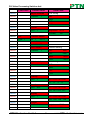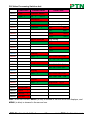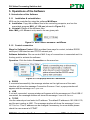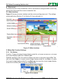
1
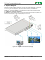
DVI Video Processing Switcher 4x4 USER MANUAL MV4 PTN DVI Video Processing Switcher 4x4 PTN Electronics Limited Version: MV42013V1.4 www.PTN-electronics.com DVI Video Processing Switcher 4x4 NOTICE: Please read this user manual carefully before using this product. This is a manual for video processor MV4. This manual is for operation instruction only, not for any maintenance usage. The functions described in this version are updated till May, 2013. Any changes of functions and parameters since then will be informed separately. Please refer to the dealers for the latest details. This manual is copyright PTN Electronics Limited. All rights reserved. No part of this publication may be copied or reproduced without the prior written consent of PTN Electronics Limited. All product function is valid till 2013-05-20. Update History Version Date Update Content 1.0 1.1 2013.01.08 2013.02.19 First version. Modified some introductions about MV4. 1.2 2013.03.07 Modified the diagram of 3x zoom-in displaying and some parameters. 1.3 2013.03.18 Modified the diagram of multi-viewer displaying, 3x zoom-in displaying. 1.4 2013.05.20 Modified the diagrams. PTN Electronics Limited www.PTN-electronics.com DVI Video Processing Switcher 4x4 Table of Contents 1. Introduction.............................................................................................................1 1.1. Introduction to MV4 ........................................................................................1 1.2. Package Contents..........................................................................................1 2. Specification ...........................................................................................................1 3. Rear Panel and Connection ...................................................................................2 4. 5. 3.1. Rear panel introduction ..................................................................................2 3.2. Connection with RS232 Communication Port ................................................3 3.3. Connection with USB Interface ......................................................................4 3.4. Twist Pair Connection ....................................................................................4 Operations of the Front Control Panel ....................................................................5 4.1. Front Panel Introduction.................................................................................5 4.2. Operations of the Menu Buttons ....................................................................6 4.3. Operations of the Input/output Selection Buttons ...........................................6 4.4. Operations of the Function Buttons................................................................7 4.5. Operations of the Customized Buttons and the Numeric keys .......................8 4.6. Menu Levels Introduction ...............................................................................8 Operations of the Software ................................................................................... 11 5.1. Introduction of the Software ......................................................................... 11 5.1.1. Installation & uninstallation .................................................................. 11 5.1.2. Control connection............................................................................... 11 5.2. Main Interface .............................................................................................. 12 5.3. Menu Bar Function Settings ......................................................................... 12 5.3.1. File Button ........................................................................................... 12 5.3.2. Connection Button ............................................................................... 13 5.3.3. View Button ......................................................................................... 13 5.3.4. Help Button.......................................................................................... 13 5.4. Main Function Settings ................................................................................ 13 5.4.1. 4x Zoom-in Function ............................................................................ 14 5.4.2. 3x Zoom-in Function ............................................................................ 14 PTN Electronics Limited www.PTN-electronics.com DVI Video Processing Switcher 4x4 5.4.3. Matrix Switching Function (Full Displaying) ......................................... 15 5.4.4. Picture in Picture (PIP) Displaying ....................................................... 15 5.4.5. Picture outside Picture (POP) Displaying ............................................ 17 5.5. Additional Function Settings ........................................................................19 5.5.1. Settings in the Auxiliary Function Area ................................................ 19 5.5.2. Settings in the Function Area on the Main Panel .................................23 5.6. Advanced Function Settings ........................................................................25 5.6.1. Display Mode Setting........................................................................... 25 5.6.2. Shortcut Button Customization ............................................................ 27 6. System Diagram ...................................................................................................28 6.1. Diagram of Video Wall Displaying ................................................................ 28 6.2. Diagram of Multi-Viewer Displaying ............................................................. 30 6.3. Diagram of Full Images Displaying .............................................................. 31 7. Firmware Upgrade ................................................................................................ 33 8. Troubleshooting & Maintenance ........................................................................... 34 9. Safety Operation Guide ........................................................................................ 35 10. After-sales Service ............................................................................................... 36 PTN Electronics Limited www.PTN-electronics.com DVI Video Processing Switcher 4x4 1. Introduction 1.1 Introduction to MV4 MV4 is a powerful, universal and user-friendly image analyzing processor with 4 DVI input ports and 4 output ports. It is not only a matrix switcher, but also a Multi-viewer or video wall processor. As a video wall processor, MV4 is able to zoom in one input image three/ four times to the outputs. And as a Multi-viewer processor, MV4 can mix inputs with any combos to one image, and then transfer to all the outputs. It also supports output resolution change, contrast & brightness adjusting, H&V zooming and moving, and bezel adjustment. MV4 provides with various ways for system control through its control ports, such as the RS232 serial port, USB interface, and the TCP/IP network port. It can be controlled easily by using the control software MV4Demo. It has a good application in various occasions, such as TV broadcasting, multi-media meeting room, network operations center, medical institutions, command & control center etc. 1.2 Package Contents 1 x MV4 1 x RS232 cable (1.35m in length) 1 x Power Cord 4 x Plastic cushions 1 x User Manual Notes: Please confirm if the product and the accessories are all included, if not, please contact with the dealers. 2. Specification Video Input Video Output Input 4 DVI Output 4 DVI Input Connector Female DB 24+5 Output Connector Female DB 24+5 Input Level T.M.D.S. 2.9V/3.3V Output Level T.M.D.S. 2.9V/3.3V Input Impedence 50Ω Output Impedence 50Ω DVI (or T.M.D.S) Switching Speed 200ns (Max.) Video General Video Signal PTN Electronics Limited 1 www.PTN-electronics.com DVI Video Processing Switcher 4x4 Bandwidth 340 MHz (6.75Gbit/s) Crosstalk <-50dB@5MHz Transport Delay 5nS (±1nS) Control Parts Control Buttons, RS232 (9-pin female D connector) Pin Configurations 2 = TX, 3 = RX, 5 = GND Control Software MV4Demo, trough USB port. Options TCP/IP control by PTNET Power Supply 100VAC ~ 240VAC, 50/60Hz Temperature -20 ~ +70℃ Humidity 10% ~ 90% Power Consumption 25W Case Dimension W483 x H44x D235mm Product Weight 5.2Kg General 3. Rear Panel and Connection 3.1 Rear panel introduction Figure 3-1 MV4 Interface Introduction PTN Electronics Limited 2 www.PTN-electronics.com DVI Video Processing Switcher 4x4 No. Name Description ① DVI INPUTS DVI-I connector, 4 input ports. ② DVI OUTPUTS DVI-I connector, 4 output ports. ③ RS232 9-pin female connector, for serial control. ④ USB USB interface, type B, for USB control and firmware update. ⑤ TCP/IP TCP/IP network port. User can control MV4 with control software MV4Demo after setting the right IP address in it. ⑥ AC100V~240V Used for accessing the household current power. 3.2 Connection with RS232 Communication Port With the RS232 port, the processing switchers can be control by the control software MV4Demo. This RS232 communication port is a female 9-pin D connector. The definition of its pins is as the table below. No. Pin Function 1 N/u Unused 2 Tx Transmit 3 Rx Receive 4 N/u Unused 5 Gnd Ground 6 N/u Unused 7 N/u Unused 8 N/u Unused 9 N/u Unused Figure 3-2 9HDF Please connect reference to the following contents. 1) Use a RS232 cable to connect the COM port of the computer to the RS232 connector of MV4. Figure 3-3 Connect with PC 2) Run the control software and select RS232 connection. 3) If connection is OK, then we can control the MV4. PTN Electronics Limited 3 www.PTN-electronics.com DVI Video Processing Switcher 4x4 3.3 Connection with USB Interface By connecting the USB interface between the switcher and the computer, user can control MV4 through its USB interface. Before controlling, please install the USB driver and the control software MV4Demo (as shown in Operations of the Software) in the controlling computer, and check if it is well connected. Plug and play and hot plug function are supported by the USB interface of MV4. 3.4 Twist Pair Connection MV4 provides with TCP/IP communication port, user can control it by using the related communication software. Activity LED: The yellow LED always blinks when the network works normally. Link LED: The green LED keeps on when the network linked. RJ-45 port: RJ45 communication port. TIA/EIA T568A TIA/EIA T568B Cable color Pin green white 1 orange white 2 green 2 orange 3 orange white 3 green white 4 blue 4 blue 5 blue white 5 blue white 6 orange 6 green 7 brown white 7 brown white 8 brown 8 brown Pin 1 1st Gro 2nd und Gro 3rd 4--5 3--6 1st Gro 2nd und Gro 3rd Cable color 4--5 1--2 1--2 3--6 und 7--8 und 7--8 Gro Gro 4th 4th up up Gro Cable connectors can Grouse T568A or T568B standard, but must be the same Notice: up on both sides of one cable. up PTN Electronics Limited 4 www.PTN-electronics.com DVI Video Processing Switcher 4x4 4. Operations of the Front Control Panel 4.1 Front Panel Introduction No. ① Name Figure 4-1 Front Panel Introduction Description Power indicator LCD Turns on when power on. ③ Menu function panel Choose the functional button required and confirm. ④ Input/output channels 4 input channels and 4 output channels. ⑤ Function pattern panel Custom panel Common functions for output image displaying effects. ② ⑥ System monitor, to indicate the operations and the real-time running state. Used for saving or recovering the customized settings. Note: Part ④, ⑤ and ⑥ are the operation areas for shortcut. 1) For the non-numeric buttons, you can use the menu buttons after you press on any numeric buttons, or use the numeric buttons directly. Example: Press the button move to enter into the menu of HP/VP settings. Press the button resolution, it will show the corresponding menu. PTN Electronics Limited 5 www.PTN-electronics.com DVI Video Processing Switcher 4x4 Press the numeric button 1 directly, and then the resolution will be set to 1080P (Without selection confirmation). 2) For the numeric buttons (Including the Input/output Selection Buttons), it will show the corresponding menu when press on any of them, uses without selection confirmation. 3) The priority of the buttons of different menu levels is showed in 4.6 Menu Levels Introduction. Below are the detailed introductions for every button. 4.2 Operations of the Menu Buttons Buttons Operation Description Switch cyclically between the menu items in the same level. For example, switch cyclically in the first level of the Menu menu between Quarter, Full, PIP, POP, Factory set, SAVE, RECALL and CLEAR. ← Return to the previous level of the menu. Enter to the next level of the menu. For example, to enter to the second level of the menu Resolution from the first level of the menu Full. Enter Select < ∧ Execute the operations selected. > ∨ To move the on-screen cursor or adjust the position of the image. Increase or decrease the value of the parameter, such as channel, resolution etc. 4.3 Operations of the Input/output Selection Buttons Buttons Operation Description Select the corresponding input image from the images of the 4 CH1 CH2 CH3 CH4 input channels. Select the corresponding output CH1′ CH2′ CH3′ CH4′ image form the images of the 4 output channels. Note: PTN Electronics Limited 6 www.PTN-electronics.com DVI Video Processing Switcher 4x4 1) While it is in 4x full screen zoom-in and 3x zoom-in function menu, it is unable to set the input or the output channels, except to set the resolution of the 4 output channels as a whole. 2) While it is in POP and PIP menu, it is able to set on a single input channel or a single output channel. 4.4 Operations of the Function Buttons Buttons Operation Description Quarter 4x full zoom-in function and 3x zoom-in function, two default display modes. full Matrix switching displaying or distribution displaying, five default modes in total. All through mode is the first one. PIP Picture in picture (PIP) displaying, 5 default modes in total. POP Picture outside picture (POP) displaying, 3 default modes in total. switch Select the input channels or the output channels, it is available together with the input channel buttons or the output channel buttons when use. resolution Set the output resolution, supports 1080P, 720P, WUXGA, UXGA, SXGA, and XGA. move Adjust the position of the image, it is available together with the direction buttons (up, down, left and right) when use. zoom Set the focus of the image to scale the image, it is available together with the direction buttons (up, down, left and right) when use. PTN Electronics Limited 7 www.PTN-electronics.com DVI Video Processing Switcher 4x4 4.5 Operations of the Customized Buttons and the Numeric keys Buttons Operation Description Customize shortcut buttons of different menu levels and SAVE save the settings. RECALL Customized menu button call. CLEAR Shortcut button, to clear the customized menu. 1 2 3 4 Numeric buttons, to set the corresponding shortcut buttons of different menu levels. Note: In the operational area of the shortcut buttons, when you press on any button, it will show the detailed information of the present menu on the LCD screen. 4.6 Menu Levels Introduction In this part, we mainly introduce the priority of the menu when operate. First Level includes: Quarter, full, PIP, POP, Factory set, SAVE, RECALL, and CLEAR. Second Level includes: resolution, set position, adjust windows, overlay, board, display, and channel Switch. Third Level includes: brightness, contrast and CH’. The relationship of each level of the menu is showed as below. First Level MENU Second Level Third Level Quarter Type 1 MENU rusolution 1 1920X1080 MENU Colour MENU OUT 1 MENU FULL Type MENU brightness 0512 contrast 100 Channel Switch 1 IN 1 OUT 1 rusolution 1 1920X1080 PTN Electronics Limited 8 www.PTN-electronics.com DVI Video Processing Switcher 4x4 First Level Second Level Third Level MENU adjust windows Fine tuning. MENU Channel 1HP 1 1HW MENU 1VP 1VW MENU Colour MENU OUT 1 MENU PIP Type MENU brightness 0512 contrast 100 Channel Switch 1 IN 1 OUT 1 rusolution 1 1920X1080 MENU Set Position Position setting. MENU Channel 1HP 0001 1VP 0001 1 MENU 1HW 0001 1VW 0001 MENU adjust windows Fine tuning. MENU Channel 1HP 1 1HW MENU 1VP 1VW MENU Overlay MENU OUT 1 CH1 CH2 CH3 CH4 1 MENU board MENU OUT ALL 2 3 4 CH1 CH2 CH3 CH4 OFF OFF OFF OFF MENU display MENU OUT 1 MENU Colour MENU OUT 1 CH1 CH2 CH3 CH4 ON PTN Electronics Limited 9 ON ON ON brightness 0512 contrast 100 www.PTN-electronics.com DVI Video Processing Switcher 4x4 First Level MENU POP Type Second Level Third Level Channel Switch 1 IN MENU 1 OUT 1 rusolution 1 1920X1080 MENU Set Position Position setting. MENU Channel 1HP 0001 1HP 0001 1HW 0001 1VW 0001 1 MENU MENU adjust windows Fine tuning. MENU Channel 1HP 1 1HW MENU 1VP 1VW MENU Overlay MENU OUT 1 CH1 CH2 CH3 CH4 1 MENU board MENU OUT ALL MENU display MENU OUT 1 2 3 4 CH1 CH2 CH3 CH4 OFF OFF OFF OFF CH1 CH2 CH3 CH4 ON MENU Colour MENU OUT 1 MENU Factory set MENU SAVE 1 MENU RECLL 1 MENU CLEAR 1 ON ON ON brightness 0512 contrast 100 Note: In the first column, MENU (in red) is showed in the first row of the displayer, and MENU (in blue) is showed in the second row. PTN Electronics Limited 10 www.PTN-electronics.com DVI Video Processing Switcher 4x4 5. Operations of the Software 5.1 Introduction of the Software 5.1.1 Installation & uninstallation MV4 can be controlled by using the software MV4Demo. Installation: Copy the software files to the controlling computer, and run the executable program MV4_v1.1.30.exe (showed in Figure 5-1). Uninstall: Delete all the software files. Note: MV4_v1.1.30.exe is only used in its own given path. Figure 5-1 MV4 Control Software—MV4Demo 5.1.2 Control connection Ways for Software Control: MV4 provides three ways for control, includes RS232 serial port, USB interface and TCP/IP network port. Software Activation: We can control MV4 if any of connections is connected and it is the key point to activate the software. Operation: Click the button Connection on the menu bar. Figure 5-2 The popup menu of Connection RS232 If connected successfully, the message window on the right corner of the main interface will show the message Connection Success. If not, a popup window will appear with the message can’t open com. USB If not well connected, a popup window will appear with the message can’t Find USB. If connected, the message window will show the message Connection Success. TCP/IP Use the network port and enter its IP address. The default IP address is 192.168.0.178, and the port number is 4001. The message window will show the message Connect NET Success. This IP address can be changed if necessary, for more details please check the user manual of PTNET. PTN Electronics Limited 11 www.PTN-electronics.com DVI Video Processing Switcher 4x4 Disconnect To disconnect the current connection. And if user wants to change another control way, please also disconnect the current connection first. 5.2 Main Interface Figure 5-3 shows the main interface and the various setting areas on it. The settings mentioned below (Section 5.3 to Section 5.6) are referred to it. Figure 5-3 Main Interface 5.3 Menu Bar Function Settings 5.3.1 File Button Function: To open the saved image display mode file, or to save a new one, or to save the current display mode file to another path. Detailed operations: Run the control software and click on the menu button File. The sub menu item Open is to open a saved image display mode file, and Save is to save the current image display mode file, and Save as is to save the current image display mode file to another path. As shown in Figure 5-4. Figure 5-4 File Menu PTN Electronics Limited 12 www.PTN-electronics.com DVI Video Processing Switcher 4x4 5.3.2 Connection Button Function: Select a control way to activate the system functions. Detailed operations: As mentioned in 5.1.2. 5.3.3 View Button Function: To set the display modes and to reset the software. Detailed operations: Click on the menu button View, the sub menu item Mode Setting is to show the current display mode, more details please check part 5.6. Window Adjustment is to auto adjust the window of software to fit control computer. Factory Reset is to clear the system stored information and it will display in 4x full screen zoom-in mode. 5.3.4 Help Button Function: Check the version of the software and the firmware of MV4. Detailed operations: Click the sub menu About Soft Version to check the version of the software or the firmware. As shown in Figure 5-5. Figure 5-5 Check the Software Version 5.4 Main Function Settings The main function area of the control software includes 4x full screen zoom-in displaying, 3x zoom-in displaying, matrix switching displaying, PIP(picture in picture) displaying, POP(picture outside picture) displaying, output image switching function and customizable shortcut button. The detailed information is showed in Figure 5-6. Figure 5-6 Main Functional Area Note: When in any one of the five modes (4x full screen zoom-in mode, 3x zoom- in mode, matrix switching mode, PIP mode, and POP mode), please notice the following information. 1) When in distribution display mode or in matrix switching display mode, it is able to set the resolution of any single output by checking the option box full mode, and also able to set as a whole resolution. But not able when in any one of the other four modes. 2) It is not able to set the correspondences between the inputs (Channel input switch) and the four outputs. PTN Electronics Limited 13 www.PTN-electronics.com DVI Video Processing Switcher 4x4 3) It is not able to set the overlay hierarchical relationship of a single input channel or to set the hierarchical relationship of all input channels. 4) When in PIP display mode or in POP display mode, it is able to set the output display state. But not able when in any one of the other four display modes. 5) It is not able to move the image on behalf in the image display mode area on the software interface. 5.4.1 4x Zoom-in Function Function: To split an input signal to four parts and displays on the displayers one to one. In fact, the input image is magnified by 4 times, as shown in Figure 6-1. Detailed Operations: While the software is running normally, click on the button , the display mode area on the software interface will show the output display mode of any one of the input channels. The four images on the displayers make up a whole image same to the input image. The buttons are used for choosing the image of any one input channel to the outputs. 5.4.2 3x Zoom-in Function Function: To split an input signal to three parts, one of them is rotated 90 degrees, and then to display on the displayers one to one. Generally there will be no output image on the first output channel (the displayer just shows a blue screen), and the images on the second, third and fourth displayers (All are rotated 90 degrees) make up a whole image same with the input image. As shown in Figure 6-2. Detailed Operations: While the software is running normally, click on the button , the display mode area on the software interface will show the output display mode of any one of the input channels. The three images on the displayers (The second, third and fourth outputs) make up a whole image same to the input image. The first displayer shows a blue screen. The buttons are used for choosing the image of any one input channel to the outputs. PTN Electronics Limited 14 www.PTN-electronics.com DVI Video Processing Switcher 4x4 5.4.3 Matrix Switching Function (Full Displaying) Function: To choose one or all the input images of the four input channels and then output to the four output displays. As shown in Figure 6-4. The default correspondence between the four displayers is like . Detailed Operations: While the software is running normally, click on the button , the display mode area on the software interface will show the output display mode of any one of the input channels. The image of each displayer is the same with the corresponding input image. And click on the button , the display mode area on the software interface will show the output display mode of any one of the input channels. The output images are the same with each other and also the same with the input image. As shown in Figure 6-5. 5.4.4 Picture in Picture (PIP) Displaying Function: MV4 is able to present all the input images of the four channels on a single screen. It means that while the screen is showing the main video, any of the other three input images (Had been compressed) also can be showed on this screen. That makes users be able to monitor other input images. In one word, it means to overlay the main video and the deputy images together. Detailed operations: While the software is running normally, click on the buttons , , , or , the display mode area on the software interface will show the display effect of all the four input channels. The images (at most three are complete) on any one displayer are made by the four input images. The buttons are used for checking the output image of any one channel. The display effects are showed in Figure 5-7 to 5-11. PTN Electronics Limited 15 www.PTN-electronics.com DVI Video Processing Switcher 4x4 From input 4, top layer. From input 2, third layer. From input 1, bottom layer. From input 3, second layer. Button Effect Figure 5-7 The First PIP Display Effect From input 1, bottom layer. From input 2 From input 3 From input 4 Button Effect Figure 5-8 The Second PIP Display Effect From input 2 From input 1, bottom Layer From input 3 From input 4 Button Effect Figure 5-9 The Third PIP Display Effect PTN Electronics Limited 16 www.PTN-electronics.com DVI Video Processing Switcher 4x4 From input 1, bottom layer From input 2 From input 3 From input 4 Effect Button Figure 5-10 The Fourth PIP Display Effect From input 3, second layer. From input 4, top layer. From input 1, bottom layer From input 2, third layer Button Effect Figure 5-11 The Fifth PIP Display Effect 5.4.5 Picture outside Picture (POP) Displaying Function: To show the output images of different channels on a single screen. It means that while the screen is showing the frame of the main video, any of the other three input images (Had been compressed) also can be showed on this screen, but locate beside the main image. That makes users be able to monitor the other input images. In one word, it means that the other three images are just beside the main image. Detailed operations: While the software is running normally, click on the button , , or , the display mode area on the software interface will show the display effect of all the four input channels. The images (all are complete) on any output channels are made by the four input images. The buttons PTN Electronics Limited are used for checking the output 17 www.PTN-electronics.com DVI Video Processing Switcher 4x4 image of any one channel. The effects are showed in Figure 5-12 to 5-14. From input 1 From input 2 From input 3 From input 4 Button Effect Figure 5-12 The First POP Display Effect From input 1 From input 2 Button From input 3 From input 4 Effect Figure 5-13 The Second POP Display Effect From input 1 From input 2 From input 3 Button From input 4 Effect Figure 5-14 The Third POP Display Effect PTN Electronics Limited 18 www.PTN-electronics.com DVI Video Processing Switcher 4x4 5.5 Additional Function Settings 5.5.1 Settings in the Auxiliary Function Area The First Auxiliary Function Area In this area, users can set the contrast, the brightness, add or remove the border of the output images. As shown in Figure 5-15. Figure 5-15 The First Auxiliary Function Area Contrast/Brightness Setting: When you need to set the image contrast/brightness of a single channel or all channels, just select the corresponding radio button and drag the slider on the slider bar to an appropriate position. And then press the button Set to confirm. In this area, the button Reset is used to set the value of contrast/brightness to the factory default (Default value of image contrast: 100, brightness: 512). Border Setting: When you need to set the border of the image of a single channel or all channels, just select the corresponding check boxes. And press the button Set to confirm your operation. The button OFF/ON is used to off-set/set the border of the input images of all channels. PTN Electronics Limited 19 www.PTN-electronics.com DVI Video Processing Switcher 4x4 The Second Auxiliary Function Area In this area, users can set the image position and zoom. As shown in Figure 5-16. Figure 5-16 The Second Auxiliary Function Area Image Position Setting: When you need to move the position of the output image of any single channel, just select the corresponding radio button and use the directional buttons Up, Down, Left and Right to an appropriate position. Image Zoom In/Out: To zoom in/out in both horizontal direction and vertical direction. The button HZoomIn and HZoomOut are for adjusting in a horizontal direction. And VZoomIn and VZoomOut are for adjusting in a vertical direction. Note: 1) The image begins to zoom in/out from the top left corner, and extends to a fixed maximum size, whenever you drag the mouse or set the values. 2) Image zoom setting is available only in Full Displaying mode. PTN Electronics Limited 20 www.PTN-electronics.com DVI Video Processing Switcher 4x4 The Third Auxiliary Function Area In this area, users can set the bezel size of the adjacent images in zoom-in model, to make the whole image looks coherently. As shown in Figure 5-17. Figure 5-17 The Third Auxiliary Function Area When in 3x zoom-in mode and 4x zoom-in mode, press the button Get to get the pezel information of the image. Enter into a new value and press the button Set to confirm. Figure 5-18 and Figure 5-19 will show you the difference between the original image and the image adjusted. Note: 1) Bezel size setting is mainly used when there is offset between the images on the displayers. 2) In Figure 5-18, the position of the images on the left side is lower than the right ones. The place marked with circle shows the effect that the images joined (before & after). PTN Electronics Limited 21 www.PTN-electronics.com DVI Video Processing Switcher 4x4 Figure 5-18 The Original Image Figure 5-19 The Image Adjusted PTN Electronics Limited 22 www.PTN-electronics.com DVI Video Processing Switcher 4x4 5.5.2 Settings in the Function Area on the Main Panel Resolution Setting MV4 supports various resolutions, such as 1080P (1920*1080), 720P (1280*720), WUXGA (1900*1200), UXGA (1600*1200), SXGA (1280*1024) and XGA (1024*768). The operation area is at the left bottom corner of the main interface. As shown in Figure 5-20. Figure 5-20 Resolution Setting In Full Displaying mode it supports to change the output resolution respectively. In other modes, the resolution of all outputs only can be set as a whole. Select the check box Full mode to set the resolution of single channel, and deselect this check box to set the resolution of all channels as a whole. And then press the button Set to confirm. The default resolution is 1080P (1920*1080). Input Channel Setting MV4 supports to assign one input image to one output channel (not the physical output interface connected with the displayer). The operation area is at the bottom of the main interface, as shown in Figure 5-21. Figure 5-21 Channel Input Selection PTN Electronics Limited 23 www.PTN-electronics.com DVI Video Processing Switcher 4x4 Overlay Hierarchical Relationship Setting Overlay Hierarchical setting in MV4 is applied for PIP display mode. In the following picture Figure 5-22, L1 (Level 1) is the bottom layer, and L4 (Level 4) is the top layer. The operation area is at the bottom of the main interface. The radio button All is for setting on all channels and Different is for setting on a single channel. Figure 5-22 Overlay Hierarchical Relationship Setting Output Display On/Off It is used to display/undisplay the output image of one channel. Select the check boxes and press the button Set to confirm. As shown in Figure 5-23. Figure 5-23 Output Display On/Off Communication Information This area is to check the connecting status between the computer and MV4 (showed in Figure 5-24), and choose a proper connection way to check if it is well connected. The detailed information is showed on the right side of the picture. Note: If the adjusting image does not synchronize with the output images show on the displays, please press the button . Figure 5-24 Additional Function Setting PTN Electronics Limited 24 www.PTN-electronics.com DVI Video Processing Switcher 4x4 5.6 Advanced Function Settings 5.6.1 Display Mode Setting This function is to switch display mode or to save the present display mode. Right-click in any area on the main interface (except the menu area) or press View on the main bar, there will be four items about modes showed on the popup menu, Figure 5-25. Figure 5-25 Popup Menu Among them, the item Load mode is to load a saved or default display mode file (switch to another display mode). Save mode is to save the present mode as a new one, which is modified base on a default mode. Figure 5-26 will show you the page of Load mode. Figure 5-26 Page of Lode mode The corresponding display mode to each number is showed in following table. Note: The number is just a code name of corresponding display mode, and it can be modified to a new name, which is good to remember. User can set it in Mode setting, press the button Set Name to rename it. And there is no limitation to name it (Name repetition, long name, and special characters are available). PTN Electronics Limited 25 www.PTN-electronics.com DVI Video Processing Switcher 4x4 No. 1,2,3, 4 5,6,7, 8 Description Default 4x zoom-in modes, the first one is for outputting the image from input channel 1, and the second one is for channel 2… and so on. Default 3x zoom-in modes, the first one is for outputting the image from input channel 1, and the second one is for channel 2… and so on. 9 Default matrix switching mode, one to one pass through. 10,11, 12,13 Default distribution display modes. 14,15 ,16,1 7,18 Default PIP display modes, the first PIP mode to the last PIP mode (from left to right). 19,20 ,21 Default POP display mode, the first POP mode to the last POP mode (from left to right). 22 Used to save the modified matrix switching mode (same to matrix switching mode No.9, but has been modified with additional function settings). PTN Electronics Limited 26 Function Button www.PTN-electronics.com DVI Video Processing Switcher 4x4 23,24 ,25,2 6 Used to save the modified distribution display mode (same to distribution display modes No.10-No.13, but has been modified with additional function settings). 27,28 ,29,3 0,31 Used to save the modified PIP mode (same to PIP display mode No.14-No.18, but has been modified with additional function settings). 32,33 ,34 Used to save the modified POP mode (same to POP display mode No.19-No.21, but has been modified with additional function settings). 5.6.2 Shortcut Button Customization With the shortcut buttons, MV4 can switch quickly to a customized display mode. The operation area is showed in Figure 5-27. Figure 5-27 Shortcut Button on the Main Interface User can set this in Mode setting: select a saved mode and press the button Set Shortcut Button, it will pop up a window to set the shortcut button. PTN Electronics Limited 27 www.PTN-electronics.com DVI Video Processing Switcher 4x4 6. System Diagram MV4 can be used in different occasions, such as multi-viewer displaying, 3x zoom-in & 4x zoom-in video wall displaying, full images matrix switching and distribution displaying. The system diagrams of the application occasions are showed as below. 6.1 Diagram of Video Wall Displaying 4x Zoom-in: It means MV4 is able to zoom in the input image and spilt to 4 parts, and then full-screen display on the output displayers one to one. Figure 6-1 Diagram of 4x Zoom-in Displaying PTN Electronics Limited 28 www.PTN-electronics.com DVI Video Processing Switcher 4x4 3x Zoom-in: There will be no output image on the first output channel (the displayer just shows a blue screen), and the images on the second, third and fourth displayers (rotated 90 degrees) make up a whole image same with the input image. Figure 6-2 Diagram of 3x Zoom-in Displaying PTN Electronics Limited 29 www.PTN-electronics.com DVI Video Processing Switcher 4x4 6.2 Diagram of Multi-Viewer Displaying Multi-Viewer: It means MV4 is able to display multi-channel output images on a single displayer. And it supports several displaying effects, such as PIP, POP etc. Figure 6-3 Diagram of Multi-Viewer Displaying PTN Electronics Limited 30 www.PTN-electronics.com DVI Video Processing Switcher 4x4 6.3 Diagram of Full Images Displaying Matrix switching: With four input ports and four output ports, MV4 is able to display any inputs to any outputs. Figure 6-4 Diagram of Matrix Switching PTN Electronics Limited 31 www.PTN-electronics.com DVI Video Processing Switcher 4x4 Distribution display: All output images are the same and also the same as the image of one input channel. Figure 6-5 Diagram of Distribution Displaying PTN Electronics Limited 32 www.PTN-electronics.com DVI Video Processing Switcher 4x4 7. Firmware Upgrade To meet with the request of different users or add function in future, the firmware of MV4 can be upgraded via USB. When you need to upgrade it, first copy the update EXE file to the PC in controlled and double chick the program to execute the following operations. Figure 7-1 The Upgrade Program File When the program is running normally, press the button on the main interface (showed in Figure 5-3). While it is connected, press the button and find the BIN file , and then it is ready to upgrade. Press the button Updata. When all are done, it will appear with a window shows the message updata sucess. Press the button OK to confrim and then user can use the latest version of the software. Figure 7-2 Main Interface of the Upgrade Program PTN Electronics Limited 33 www.PTN-electronics.com DVI Video Processing Switcher 4x4 8. Troubleshooting & Maintenance 1) When images of terminal unit output with ghost, such as the projector output with ghost. Generally this is not a unit faulty, this may be caused by an incorrect setting on the projector or a bad quality of cable. Please check the projector’s setting or try another high quality connection cable. 2) When there is a color losing or no video signal output, please check the input and output end connections of the cables. 3) When user cannot control the switcher by computer through its COM port, please check the COM port number in the software and make sure the COM port is in good condition, or use the USB interface or the TCP/IP network port. 4) When there is no output images: Check if there is any signal at the input. Check if there is any signal at the output. We can check these by using an oscilloscope or a multimeter. If there is no signal input/output, maybe the input/output cables broken or the connectors loosen, please change for another cable. Make sure the destination device is exactly on the controlled output channel. If not the problem mentioned above, probably there is something broken inside the unit, please send it to the dealer for repairing. 5) If the POWER indicator doesn’t work or no respond to any operation, please make sure the power cord connection is good. 6) If the output image is interfered, please make sure the system is grounded well. 7) If the static becomes stronger when connecting the video cables, it probably due to the incorrect grounding, please correct it otherwise it would damage the switcher. 8) If the switcher cannot be controlled by the buttons on the front panel or any of the control ports, the switcher may have broken. Please send it to the dealer for repairing. PTN Electronics Limited 34 www.PTN-electronics.com DVI Video Processing Switcher 4x4 9. Safety Operation Guide In order to guarantee the reliable operation of the equipments and safety of the staff, please abide by the following proceeding in installation, using and maintenance: 1) The system must be earthed properly. Do not use two blades plugs and ensure the alternating power supply ranged from 100v to 240v and from 50Hz to 60Hz. 2) Do not put the switcher in a place of too hot or too cold. 3) As the power generating heat when running, the working environment should be maintained fine ventilation, in case of damage caused by overheat. 4) Cut off the general power switch in humid weather or left unused for long time. 5) Before following operation, ensure that the alternating current wire is pull out of the power supply: Take off or reship any components of the equipment. Take off or rejoin any pin or other link of the equipment. 6) As to non-professional or without permission, please DO NOT try to open the casing of the equipment, DO NOT repair it on your own, in case of accident or increasing the damage of the equipment. 7) DO NOT splash any chemistry substance or liquid in the equipment or around. PTN Electronics Limited 35 www.PTN-electronics.com DVI Video Processing Switcher 4x4 10. After-sales Service 1) If there appear some problems when running MV4, please check and deal with the problems reference to this user manual. Any transport costs are borne by the users during the warranty. 2) You can email to our after-sales department or make a call, please tell us the following information about your cases. Product version and name. Detailed failure situations. The formation of the cases. 3) We offer products for all three-year warranty, which starts from the first day you buy this product (The purchase invoice shall prevail). 4) Any problem is same with one of the following cases listed, we will not offer warranty service but offer for charge. Beyond the warranty. Damage due to incorrectly usage, keeping or repairing. Damage due to device assembly operations by the maintenance company non-assigned. No certificate or invoice as the proof of warranty. The product model showed on the warranty card does not match with the model of the product for repairing or had been altered. Damage caused by force majeure. Remarks: For any questions or problems, please try to get help from your local distributor, or email PTN at: [email protected] PTN Electronics Limited 36 www.PTN-electronics.com