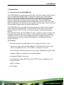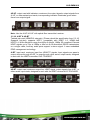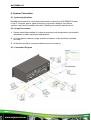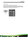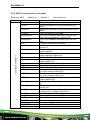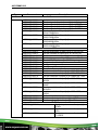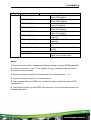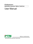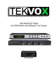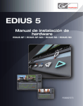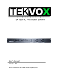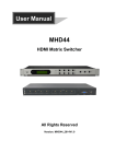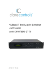
1
AVG-DMM1616
Features
The AVG-DMM1616 is a high-performance
video and audio modular matrix switcher
supporting a maximum of 16 input signal
sources and 16 output displays synchronously.
Modular chassis with configurable
I/O slots, ranging from 4x4 to
16x16.
Various I/O cards, includes HDMI,
HDBaseT, SD/HD/3G-SDI, DVI
and VGA cards (Compatible with
YUV, YC & CVBS.) to configure
any matrix.
True cross-point switching, any
input to any output, regardless of
signal format.
Supports HDMI1.4a, supports 3D.
Supports 4K.
Integrated HDBaseT technology.
Controllable via button, RS232 &
optional TCP/IP, also compatible
with 3rd party control systems.
HDCP compliant.
LCD display.
AVG-DMM1616
PLEASE READ THIS PRODUCT MANUAL CAREFULLY
BEFORE USING THIS PRODUCT.
This manual is only for operation instruction only, and
is not to be used in a maintenance capacity. The
functions described in this version are current as at
March 2015. Any changes of functions and
operational parameters will be updated in future
manual versions. Please refer to your dealer for the
latest product details.
Version 1.0 1/3/15
AVG-DMM1616
SAFETY OPERATION GUIDE
In order to guarantee the reliable operation of the equipment and safety of the
user, please abide by the following procedures in installation, use and
maintenance:
1. The system must be earthed properly. Please do not use two blade plugs
and ensure the AC power supply ranges from 100v to 240v and from 50Hz
to 60Hz.
2. Do not install the switcher in an environment where it will be exposed to
extreme hot or cold temperatures.
3. This unit will generate heat during operation, please ensure that you allow
adequate ventilation to ensure reliable operation.
4. Please disconnect the unit from mains power if it will be left unused for a
long time.
5. Please DO NOT try to open the casing of the equipment, DO NOT attempt to
repair the unit. Opening the unit will void the warranty. There are high
voltage components in the unit and attempting to repair the unit could result
in serious injury.
6. Do not allow the unit to come into contact with any liquid as that could result
in personal injury and product failure.
AVG-DMM1616
TABLE OF CONTENTS
Introduction .............................................................................................................. 1
Introduction to the AVG-DMM1616............................................................... 1.1
Features ....................................................................................................... 1.2
MMX signal card (changeable cards) ................................................ 1.2.1
What’s in the Box ........ ……………………………………………………………………2
Product Appearance of the AVG-DMM1616 ........................................................... 3
Front Panel ................................................................................................... 3.1
Rear Panel.................................................................................................... 3.2
Changeable Cards........................................................................................ 3.3
4I-DV & 4O-DV ................................................................................ 3.3.1
4I-DS& 4O-DS ................................................................................. 3.3.2
4I-HD & 4O-HD ................................................................................ 3.3.3
4I-VG & 4O-VG ................................................................................ 3.3.4
4I-VA ............................................................................................... 3.3.5
4I-SD & 4O-SD ................................................................................ 3.3.6
4I-TP & 4O-TP ................................................................................. 3.3.7
4I-UH & 4O-UH ................................................................................ 3.3.8
4I-UF & 4O-UF ................................................................................. 3.3.9
4I-BT & 4O-BT ............................................................................... 3.3.10
System Connection .................................................................................................. 4
System Applications ..................................................................................... 4.1
Usage Precautions ....................................................................................... 4.2
Connection Diagram ..................................................................................... 4.3
System Operations................................................................................................... 5
Front Panel Button Control ........................................................................... 5.1
IR Control ..................................................................................................... 5.2
RS232 Control .............................................................................................. 5.3
Connection with the RS232 Communication Port ........................... 5.3.1
RS232 Communication Commands ................................................ 5.3.2
TCP/IP Control ............................................................................................. 5.4
Control Modes ................................................................................ 5.4.1
TCP/IP Settings .............................................................................. 5.4.2
Specifications ........................................................................................................... 6
Main Unit ...................................................................................................... 6.1
Changeable Cards........................................................................................ 6.2
4I-DV & 4O-DV ................................................................................ 6.2.1
4I-DS& 4O-DS ................................................................................. 6.2.2
4I-HD & 4O-HD ................................................................................ 6.2.3
4I-VG & 4O-VG ................................................................................ 6.2.4
AVG-DMM1616
4I-VA ............................................................................................... 6.2.5
4I-SD & 4O-SD ................................................................................ 6.2.6
4I-TP & 4O-TP ................................................................................. 6.2.7
4I-UH & 4O-UH ................................................................................ 6.2.8
4I-UF & 4O-UF ................................................................................. 6.2.9
4I-BT & 4O-BT ............................................................................... 6.2.10
Troubleshooting & Maintenance ............................................................................. 7
AVG-DMM1616
1. Introduction
1.1. Introduction to the AVG-DMM1616
The AVG-DMM1616 is a high-performance video and audio modular matrix switcher
from our Digital Media Matrix range. It supports a maximum of 16 input signal
sources and 16 output displays synchronously. It supports different video signals
with true cross-point switching. Every video and audio signal is transmitted and
switched independently to decrease signal attenuation. The AVG-DMM1616
supports various interchangeable cards including HDMI, 4K, DVI, VGA, SDI, Fiber
Optic and HDBaseT etc, and all the cards support hot plug & play. Users can choose
to insert different signal cards for different applications.
The AVG-DMM1616 has a power fail memory function and audio can break away
from or follow the video switched. It has an RS232 port for serial control and an
optional IP port for TCP/IP control, it can also be easily controlled by third-party
devices.
With its flexible design, the AVG-DMM1616 can be used for a range of projects and
is capable of being an ‘all-in-one solution’. It is the perfect solution for multimedia
conference rooms, control rooms, broadcasting rooms, shopping centers etc. It is
comfortable handling all the audiovisual management, including the switching,
driving, scaling etc.
1.2. Features
Modular chassis with configurable I/O slots, ranging from 4x4 to 16x16.
Various I/O cards, includes HDMI, HDBaseT, SD/HD/3G-SDI, DVI and VGA
cards (Compatible with YUV, YC & CVBS.) to configure any matrix.
True cross-point switching, any input to any output, regardless of signal format.
Supports HDMI1.4a, supports 3D, 4K cards available.
Integrated HDBaseT technology.
Controllable via button, RS232 & optional TCP/IP, also compatible with 3rd
party controllers.
HDCP compliant.
LCD display.
AVG-DMM1616
1.2.1. MMX signal card (changeable cards)
To suit different applications and users, the AVG-DMM1616 cards are classified into
the following models:
Spec
Inputs
Signal Format
4I-HD
4I-DV
4I-DS
4
4
4
4I-VG
4I-VA
4
4
HDMI
DVI
DVI, HDMI, VGA, AV,
YPbPr
VGA
VGA& PCM audio
Inputs
Signal Format
4 inputs & 4 LOOP outputs
for each channel)
4
4
4
4
SDI
Models
Spec
Models
4I-SD
4I-TP
4I-UH
4I-UF
4I-BT
HDMI TP, IR, RS232
HDMI& PCM Audio
Optical Fiber
HDBT, RS232, Audio
Input Cards
Spec
Outputs
Signal Format
4O-HD
4O-DV
4O-DS
4
4
4
4O-VG
4O-SD
4 VGA, 4 Stereo audio
4 outputs & 4 LOOP
outputs for each channel)
4
4
4
4
HDMI
DVI
DVI, HDMI, VGA, AV,
YPbPr
VGA, analog audio
SDI
Models
4O-TP
4O-UH
4O-UF
4O-BT
HDMI TP, IR, RS232
HDMI& PCM Audio
Optical Fiber
HDBT, RS232, Audio
AVG-DMM1616
2. Package List
1 x AVG-DMM1616
1 x RS232 cable
4 x Plastic cushions
1 x IR remote (The cell battery is not included)
1 x Power Cord
1 x User manual
Note: Please confirm if the product and the accessories are all included, if not,
please contact your dealer.
AVG-DMM1616
3. Product Appearance of the AVG-DMM1616
3.1. Front Panel
No.
①
②
Name
③
④
IR
Power
indicator
LCD screen
INPUTS
⑤
OUTPUTS
⑥
MENU
Description
IR sensor, receives IR signal sent from IR remote
Illuminates red once powered on
Displays real-time operation status
Buttons for input channels with green back-light indication,
ranges from 0~ 9, 16 selectable channels in total.
Buttons for output channels with green back-light indication,
ranges from 0 ~ 9, 16 selectable channels in total.
AV: transfer video and audio signal synchronously
,: division button, to divide the output channels when
switching to more than one channel.
UNDO: Undo button, to resume to the status before the
command just performed.
ENTER: confirm switching operation. Operation will not be
executed by the matrix without confirmation.
ALL: select all input/output channel
THROUGH: To transfer the signals directly to the
corresponding output channels.
: Backspace button, to backspace the latest input button.
Note: Pictures shown in this manual are for reference only.
AVG-DMM1616
3.2. Rear Panel
No.
Name
①
②
③
INPUTS
OUTPUTS
Power
switch
TCP/IP
RS232
Power ports
④
⑤
⑥
Description
Input signal card slots, 4 in total
Output signal card slots, 4 in total
Switch between AC110V and AC230V to access different
power
(Optional) Used for TCP/IP control port
Serial control port, connect with RS232 port of control device.
Connect with household alternating current power, including
one redundant power.
Note: There are only 4 input and 4 output slots for AVG-DMM1616, which enables
only 4 input cards and 4 output cards to be installed on AVG-DMM1616. The
input/output cards can be changed based on your requests and supports hot plug
and play.
Pictures shown in this manual are for reference only.
3.3. Changeable Cards
AVG-DMM1616 support expansion through various changeable input/ output cards
of different signals including DVI, HDMI, VGA, twisted pair, SDI etc. Here is a brief
introduction to the changeable cards.
AVG-DMM1616
3.3.1. 4I-DV & 4O-DV
DVI signal card. (Please check the specification from 5.2.1) It is fully compatible with
HDMI1.3 and HDCP, but not supporting analog signals. It uses embedded EDID
management technology, supporting DDC. 4I-DV: input card, maximum four input
signals. Input signals can pass to an output device through 4O-DV, or pass through
other series output cards.
4O-DV: output card, maximum four output signals, output signals from 4I-DV, or
other series of input cards.
Pin Layout of the DVI-I connector (Dual-Link). (Female)
PIN
1
2
3
Function
T.M.D.S.Data2T.M.D.S.Data2+
T.M.D.S. Data 2/4 Shield
PIN
13
14
15
4
5
6
7
T.M.D.S. Data 4T.M.D.S. Data 4+
DDC Clock
DDC Data
16
17
18
19
8
9
10
Analog Vertical Sync
T.M.D.S.Data1T.M.D.S.Data1+
20
21
22
11
12
T.M.D.S.Data1/3 Shield
T.M.D.S.Data3-
23
24
Function
T.M.D.S.Data3+
+5V Power
Ground (return for
+5V, Hsync and
Vsync)
Hot Plug Detect
T.M.D.S. Data 0T.M.D.S. Data 0+
T.M.D.S. Data 0/5
Shield
T.M.D.S.Data5T.M.D.S.Data5+
T.M.D.S. Clock
Shield
T.M.D. S. Clock +
T.M.D.S .Clock-
AVG-DMM1616
3.3.2. 4I-DS& 4O-DS
Seamless DVI signal card. (Please check the specification from 5.2.2)
It is fully compatible with HDMI1.3 and HDCP 1.2, and supports seamless
transmission for high-definition DVI, HDMI, VGA, AV, YPbPr signals. It can
automatically identify the format of the input signal, and the output resolution can be
adjusted.
It uses embedded the EDID management technology, supporting DDC. 4I-DS:
seamless input card, maximum four input signals. Input signals can pass to output
devices through 4O-DS, or pass through the other series of output cards.
4O-DS: seamless output card, maximum four output signals. Output signals can
come from 4I-DS, or from the other series input cards. It supports memory off
function for resolution, signal format and HDCP compliance status.
Note: When 4O-DS works with input cards except 4I-DS, adjust the 4 input signals
to any one of the following 5 resolutions to enable seamless output: 1024x768,
1280x720, 1600x1200, 1920x1080, 1920x1200. DVI interfaces on the signal card
are the same as the interfaces on 4I-DV& 4O-DV.
3.3.3. 4I-HD & 4O-HD
HDMI signal card. (Please check the specification from 5.2.3) It uses embedded
EDID management technology, supporting DDC. It is also compatible with DVI signal
(HDCP required). 4I-HD: input card, maximum four input signals. Input signals can
pass to an output device through 4O-HD, or pass through other series output cards.
AVG-DMM1616
4O-HD: output card, maximum four output signals, output signals from 4I-HD, or
other series input cards.
Pin layout of the HDMI connectors (female).
No.
1
2
3
4
5
6
7
8
9
10
Signal Name
TMDS Data 2+
TMDS Data 2 Shield
TMDS Data 2TMDS Data 1+
TMDS Data 1 Shield
TMDS Data 1TMDS Data 0+
TMDS Data 0 Shield
TMDS Data 0TMDS Clock+
No.
20
19
18
17
16
15
14
13
12
11
Signal Name
SHELL
Hot Plug Detect
+5V Power
Ground
DDC Data
DDC Clock
No Connect
CEC
TMDS ClockTMDS Clock Shield
3.3.4. 4I-VG & 4O-VG
VGA signal card. (Please check the specification from 5.2.4) Scale all inputs to
1080p. Compatible with C-Video, YUV, YC (Factory preset function). The bandwidth
is up to 350MHz (-3dB);
Supporting RGBHV, RGsB, RGBS, RsGsBs, YUV, YC and Composite video. 4I-VG:
input card, maximum four input signals. Input signals can pass to output devices
through any series output cards.
4O-VG: output card, maximum four VGA output signals and 4 stereo audio outputs,
output video signal from 4I-VG, or other series input cards, outputs audio signal from
the audio of the input signal.
AVG-DMM1616
Pin layout of the VGA connectors (female):
Pin Number
Pin 1
Pin 2
Pin 3
Pin 4
Pin 5
Pin 6
Pin 7
Pin 8
Signal Name
RED
GREEN
BLUE
ID2/RES
GND
RED_RTN
GREEN_RTN
BLUE_RTN
Pin Number
Pin 9
Pin 10
Pin 11
Pin 12
Pin 13
Pin 14
Pin 15
Connect the devices via VGA converting cable as shown below:
Connect with Component Video (YPbPr) Source
Connect with Composite Video (C-VIDEO) Source
Signal Name
KEY/PWR
GND
ID0/RES
ID1/SDA
HSync
VSync
ID3/SCL
AVG-DMM1616
3.3.5. 4I-VA
VGA signal card. (Please check the specification from 5.2.5) Scale all inputs to
1080p. Compatible with C-Video, YUV, YC (Factory preset function). Supporting
RGBHV, RGsB, RGBS, RsGsBs, YUV, YC and Composite video.
4I-VA: input card, maximum four VGA inputs and four stereo audio inputs. Input
signal can pass to output devices through any series of output cards.
The VGA connector and source connection is same with the 4I-VG.
3.3.6. 4I-SD & 4O-SD
SDI signal card. (Please check the specification from 5.2.6) It is compatible with
different SDI signal formats, including SD/HD/3G-SDI (adaptive) Every port has a
loop output for local monitoring.
4I-SD: input card, maximum four input signals. Input signals can pass to output
devices through 4O-SD, or pass through other series output cards.
4O-SD: output card, maximum four output signals, output signals from 4I-SD, or
other series input cards.
The BNC connector is shown as the figure below.
AVG-DMM1616
3.3.7. 4I-TP & 4O-TP
Twisted pair card (HDMI/DVI extender). (Please check the specification from 5.2.7)
Supports HDTV, compatible with HDMI1.3 and HDCP 4I-TP: input card, maximum
input four HDMI TP signals. Input signals can pass to output devices through 4O-TP,
or pass through other series output cards, designed to work with the AVGTPHD402T.
4O-TP: output card, maximum output four HDMI TP signal, output signals from 4ITP, or other kinds of input cards, designed to work with the AVG-TPHD402R.
Pin layout of the RJ45 connectors:
Two different connection standards can be chosen; the connectors of the same
cable should use the same standard at each end.
TIA/EIA T568A
TIA/EIA T568B
Cable color
Cable color
1
green white
1
orange white
2
green
2
orange
3
orange white
3
green white
4
blue
4
blue
5
blue white
5
blue white
6
orange
6
green
7
brown white
7
brown white
8
brown
8
brown
AVG-DMM1616
Note: Cable connectors MUST be metal, and the shielded layer of the cable MUST
be connected to the connector’s metal shell, to ensure reliable grounding.
3.3.8. 4I-UH & 4O-UH
4K HDMI signal card. (Please check the specification from 5.2.8) Supports hotplugging, HDMI 1.4& HDCP 1.4 compliant; Compatible with DVI signal; Supports
high-definition HDMI sources up to 4kx2k, 1080p 3D compliant; Provides auxiliary
audio port to output the HDMI embedded audio. It uses embedded EDID
management technology.
4I-UH: input card, maximum four input signals. Input signals can pass to output
devices through 4O-UH, or pass through other series output cards.
4O-UH: output card, maximum four output signals, output signals from 4I-UH, or
other series input cards, HDCP compliant status set via RS232 command.
3.3.9. 4I-UF & 4O-UF
4K optical signal card. (Please check the specification from 5.2.9) Supports hotplugging; High bandwidth: 10.2Gbps; Compliant with HDMI 1.4, able to transmit
4K×2K& 1080P 3D (max) signals; Supports multi-mode transmission up to 300m and
single mode transmission up to 1km.
4I-UF: input card with indicators, maximum four input signals, corresponding
indicator illuminates green when there is an input signal. Input signals can pass to
output devices through 4O-UF, or pass through other series output cards.
AVG-DMM1616
4O-UF: output card with indicators, maximum four output signals, output signals from
4I-UF, or other series input cards; corresponding indicator illuminates green when
there is an output signal.
Note: Use the 4I-UF/ 4O-UF with optical fiber transmitter/ receiver.
3.3.10. 4I-BT & 4O-BT
Twisted pair card (HDMI/DVI extender). (Please check the specification from 5.2.10)
Supports hot-plug, supports HDTV, compatible with HDBT 1.0, HDMI1.4a&
HDCP1.4; Wide resolution range from 480p to 4kx2k, 1080p 3D compliant; Extends
HDBT signals up to 70m at 1080p or 40m at 4k; Bi-directional RS232 transmission
on a single cable; Auxiliary audio ports support a stereo signal. It uses embedded
EDID management technology.
4I-BT: input card, maximum input four HDMI TP signals. Input signals can pass to
output devices through 4O-BT, or pass through other series output cards, designed
to work with the HDBT transmitter AVG-TPHD402T.
4O-BT: output card, maximum output four HDBT signal, output signals from 4I-BT, or
other series input cards, designed to work with the HDBT receiver AVG-TPHD402R.
AVG-DMM1616
4. System Connection
4.1. System Applications
Reliable performance for control and transmission makes the AVG-DMM1616 ideal
in the IT computer space, signal monitoring, big screen displays, conference
systems, television broadcast, education, banking and security institutions etc.
4.2. Usage Precautions
1. System should be installed in a clean environment with temperature and humidity
maintained to within equipment specification.
2. All of the power switches, plugs, sockets and power cords should be insulated
and safe.
3. All devices should be connected before power is turned on.
4.3. Connection Diagram
AVG-DMM1616
5. System Operations
5.1. Front Panel Button Control
Users can control the AVG-DMM1616 simply and directly with its front panel buttons.
To switch AV/ and A/ V signal, please operate the buttons using the following format:
Format: “Input Channel” + “AV” +“Output Channel “+“Enter”
Note:
1) “Switch Mode”: Audio & Video synchronous (AV) or break away switching mode
(Audio/ Video)
2) “Input Channel”: Push the number of the input channel to be controlled,
3) “Output Channel”: Push the number of the output channels to be controlled. Press
“All” to select all the outputs.
4) Use “,” button to separate multiple I/O channels, and press the “ENTER” button to
confirm the operation.
5) The input/output channels on the rear panel are slotted from left to right, top to
bottom.
6) The input delay time between two numbers of every input & output channel must
be less than 5 seconds; otherwise the operation will be cancelled.
Example:
1. To transfer input 1 to output 11, press input “1”, output “0” “1” and “Enter”.
2. To transfer signals from input 1 to all output channels, press buttons in this order:
“1”, “All”.
Other Functional Buttons:
Buttons
UNDO
Description
Returns to the
previous
status
Backspace
the last
operation
THROUGH Get one to
one I/O
connection,
e.g. input 1->
output 1,
input 2->
output 2.
Operation
State 1: Input 6 -> output 6 Press input “6” + “AV”+
output 4 to change the connection. Press “Undo” to
return to State 1.
If you press buttons “1”, “AV”, “2”, “ ” in order, then “2”
will be canceled.
Format: “Input Channel”+”Through” If you press
buttons “ALL”, “THROUGH” in order, then the result
will be like input 1 output 1, input 2 output 2, input
3 output 3 … input 16 output 16.
AVG-DMM1616
5.2. IR Control
With the IR remote, the AVG-DMM1616 can be controlled remotely. As the function
buttons on the IR remote are the same as the ones on the front panel, the IR remote
shares the same operations and commands with the control panel. Press the buttons
in below format:
“Input Channel” + “Switch Mode” +“Output Channel”
Input channel
buttons, including
1~10+
Menu buttons, including
switching buttons and
function buttons
Output channel
buttons, including
1~10+
AVG-DMM1616
5.3. RS232 Control
5.3.1. Connection of the RS232 Communication Port
In addition to the front control panel and IR remote, the AVG-DMM1616 can be
controlled by a far-end control system using the Ethernet port or via the RS-232
communication port. This RS-232 communication port is a female 9- D connector.
The definition of its pin layout is shown in the table below.
No.
1
2
3
4
5
6
7
8
9
Function
N/C Unused
Tx
Transmit
Rx
Receive
N/C Unused
Gnd Ground
N/C Unused
N/C Unused
N/C Unused
N/C Unused
AVG-DMM1616
5.3.2. RS232 Communication Commands
Baud rate: 9600
Type
Data bit: 8
Command
/*Type;
/%Lock;
Stop bit: 1
Parity bit: none
Recall[Y].
Clear[Y].
PWON.
Description
Query the models information.
Lock the keyboard of the control panel on the
Matrix.
Unlock the keyboard of the control panel on the
Matrix.
Query the version of firmware
Turn off the feedback command from the com
port. It will only show the “switcher OK”.
Turn on the feedback command from the com
port.
To cancel the previous operation.
Switch to the “demo” mode, 1->1, 2->2, 3->3 …
and so on.
Transfer signals from the input channel [x] to all
output channels
Transfer all input signals to the corresponding
output channels respectively.
Switch off all the output channels.
Transfer signals from the input channel [x] to the
output channel [x].
Switch off the output channel [x].
Switch on all the output.
Switch on output [x].
Transfer the video signals from the input channel
[x1] to the output channel [x2].
Transfer the audio signals from the input channel
[x1] to the output channel [x2].
Transfer signal from the input channel [x1] to the
output channel [x2].
Query the input channel to the output channel
[x].
Query the input channel to the output channels
one by one.
Save the present operation to the preset
command [Y]. [Y] ranges from 0 to 9.
Recall the preset command [Y].
Clear the preset command [Y].
Power ON.
PWOFF.
HDCPON.
HDCPOFF.
/V00.
Enter into standby mode.
Turn on the HDCP output.
Turn off the HDCP output.
Query the version of backboard software.
/%Unlock;
/^Version;
/:MessageOff;
/:MessageOn;
Undo.
Demo.
[x]All.
All#.
Commands for Main Unit
All$.
[x]#.
[x]$.
All@.
[x]@.
[x1]V[x2].
[x1]A[x2].
[x1]B[x2].
Status[x].
Status.
Save[Y].
AVG-DMM1616
Type
Command
UpgradeIntEDID[x].
EDIDUpgrade[x].
EDID/[x]/[y].
EDIDG[x].
EDIDMInit.
EDIDM[X]B[Y].
USER/[Y]/[X]:*****;
0911%.
USER/I/[x]:0622%;
USER/I/[x]:0623%;
USER/I/[x]:0624%;
USER/I/[x]:0625%;
USER/I/[x]:0626%;
Commands for Main Unit
USER/I/[x]:0627%;
USER/I/[x]:0628%;
USER/I/[x]:0619%;
USER/I/[x]:0621%;
USER/I/[x]:0629%;
USER/I/[x]:0620%;
USER/I/[x]:0617%;
USER/I/[x]:0606%;
USER/I/[x]:0698%;
Description
Upgrade built-in EDID data. Supports 6 types of
EDID data (see Note 6). When the switcher gets
the command, it will show a message to send
EDID file (.bin file).
Upgrade EDID data of input ports When the
switcher gets the command, it will show a
message to send EDID file (.bin file). Operations
will be canceled after 10 seconds.
Set the EDID data of input port [x] to built-in
EDID data of type [y]. The value of [y] varies
from 1~6. The EDID data types are same as
mentioned above.
Get EDID data from output channel X and
display the data on serial port control software.
[x] is the output port number.
Recover the factory default EDID data for every
input channel.
Manual EDID switching. Enable input [Y] to learn
the EDID data of output[X]. If there is problem
learning the EDID data, it will automatically set
the default EDID data for input [Y].
Custom command for signal cards, [Y]=I/O; [X]=
port number; *****: User-definable command,
e.g. 0623%
Restore factory default.
4I-VA
Set the signal of input channel [x] to VGA.
Set the signal of input channel [x] to YCBCR.
Set the signal of input channel [x] to SVIDEO.
Set the signal of input channel [x] to CVIDEO.
Set the resolution of input [x] to
1024x768@60Hz.
Set the resolution of input [x] to
1280X720@60Hz.
Set the resolution of input [x] to
1280X800@60Hz.
Set the resolution of input [x] to
1360X768@60Hz.
Set the resolution of input [x] to
1600X1200@60Hz.
Set the resolution of input [x] to
1920X1080@60Hz.
Set the resolution of input [x] to
1920X1200@60Hz.
Restore to factory default.
Auto-adjust VGA signal
Update software
AVG-DMM1616
Type
Command
USER/I/[x]:0698%;
USER/I/[x]:0622%;
USER/I/[x]:0623%;
USER/I/[x]:0624%;
USER/I/[x]:0625%;
USER/I/[x]:0626%;
USER/I/[x]:0627%;
USER/I/[x]:0628%;
USER/I/[x]:0629%;
USER/I/[x]:02xx%;
USER/I/[x]:03xx%;
USER/I/[x]:04xx%;
USER/I/[x]:05xx%;
USER/I/[x]:0606%;
USER/I/[x]:0607%;
USER/I/[x]:0608%;
USER/I/[x]:0614%;
USER/I/[x]:0617%;
USER/I/[x]:0619%;
USER/I/[x]:0626%;
USER/I/[x]:0627%;
USER/I/[x]:0628%;
USER/I/[x]:0629%;
USER/I/[x]:0620%;
USER/I/[x]:0621%;
USER/I/[x]:0698%;
USER/I/[x]:0686%;
USER/I/[x]:0687%;
USER/O/[x]:0201%;
USER/O/[x]:0202%;
USER/O/[x]:0203%;
Description
4I-VG
Update software
Set the signal of input channel [x] to VGA.
Set the signal of input channel [x] to YCBCR.
Set the signal of input channel [x] to SVIDEO.
Set the signal of input channel [x] to CVIDEO.
Set the resolution of input [x] to
1024x768@60Hz.
Set the resolution of input [x] to
1280X720@60Hz.
Set the resolution of input [x] to
1280X800@60Hz.
Set the resolution of input [x] to
1920X1080@60Hz.
4I-DS
Set the brightness of input [x] to xx, xx=00~99
Set the contrast of input [x] to xx, xx=00~99
Set the saturation of input [x] to xx, xx=00~99
Set the sharpness of input [x] to xx, xx=00~99
(For 4I-DS/ VA) Auto-adjust VGA input signal
Set picture’s color temperature
Configure image scale
Configure picture mode
Restore to factory default.
Set the resolution of input [x] to 1360x768, HD
Set the resolution of input [x] to 1024x768, XGA
Set the resolution of input [x] to 1280x720, 720P
Set the resolution of input [x] to 1280x800,
WXGA
Set the resolution of input [x] to 1920x1080,
1080P
Set the resolution of input [x] to 1920x1200,
WUXGA
Set the resolution of input [x] to 1600x1200,
UXGA
Software update
Set the output signal of input [x] to HDMI
Set the output signal of input [x] to DVI
4O-DS
Set the input source of output [x] to
YPbPr
Set the input source of output [x] to
VGA
Set the input source of output [x] to
C-VIDEO
AVG-DMM1616
Type
Command
USER/O/[x]:0804%;
USER/O/[x]:0813%;
USER/O/[x]:0824%;
USER/O/[x]:0826%;
USER/O/[x]:0837%;
USER/O/[x]:0106%;
USER/O/[x]:0107%;
GetResolution[x].
GetVGAPortMode[x].
AUDIO[X]I[Z].
Description
Set the resolution of output [x] to
1280x720P @60Hz
Set the resolution of output [x] to
1280x1080P @60Hz
Set the resolution of output [x] to
1024x768 @60Hz
Set the resolution of output [x] to
1280x1024 @60Hz
Set the resolution of output [x] to
1920x1200 @60Hz
Switch on the HDCP compliance of
output [x]
Switch off the HDCP compliance of
output [x]
Capture output resolution of output
[x]
Query the output status of VGA
port [x]
4I-UH/BT
Select audio source from audio
inputs or AV signal inputs
Notes:
1. Please disconnect all the twisted pairs before sending command EDIDUpgrade[X].
2. In above commands, “[”and “]” are symbols for easy reading and do not need to
be typed in actual operation.
3. Please remember to end the commands with the ending symbols “.” or “;”.
4. Type the command carefully, it is case-sensitive.
5. Commands pertaining to EDID only available for signal cards that support EDID
management.
6. The switcher boasts 6 in-built EDID data memories, the chart below illustrates the
detailed information:
AVG-DMM1616
No.
1
2
3
4
5
6
Detailed Information
1080p 2D 5.1CH
1080p 2D 2.0CH
720p 2D 5.1CH
720p 2D 2.0CH
4kx2k 2D 5.1CH
4kx2k 2D 2.0CH
Update in-built EDID data by sending command UpgradeIntEDID[x].
Examples:
1. Transfer signals from an input channel to all output channels: [x]All.
Example: Send “3All.” to transfer signals from the input 3 to all output channels.
2. Transfer all input signals to corresponding output channels
respectively: All#.
Example: If this command is carried out, the status of matrix will be: 1->1, 2->2, 3->3,
4->4…… 8->8….
3. Switch off all the output channels: All$.
Example: After running this command, there will be no signals on all the outputs.
4. Switch off the detail feedback command from the COM port:
/:MessageOff;
But, it will leave the “switch OK” as the feedback, when you switch the matrix.
5. Switch on the detail feedback command from the COM port:
/:MessageOn;
It will show the detail switch information when it switch. Example: when switch 1->2,
it will feedback “AV01 to 02”.
6. Transfer signals from an input channel to corresponding output
channel: [x]#.
Example: “5#.” to transfer signals from the input5 to the output5.
7. Switch off an output channel: [x]$.
Example: “5$.” to switch off the output 5.
AVG-DMM1616
8. Switch signal: [x1] B[x2].
Example: “12B12,13,15.” to transfer signal from input12 to output No.12,13,15.
9. Query the input channel to the output channel [x]: Status[x].
Example: Send “Status3.” to Query the input channel to the output 3.
10. Query the input channel to the output channels one by one: Status.
Example: “Status.” to Query the input channel to the output channels one by one.
11. Save the present operation to the preset command [Y]: Save[Y].
Example: “Save7.” to save the present operation to the preset command No.7.
12. Recall the preset command [Y]: Recall[Y]. Example: “Recall5.” to recall the
preset command No.5.
13. Clear the preset command [Y]: Clear[Y]. Example: “Clear5.” to clear the
preset command No.5.
14. EDID management command:. EDIDM[X]B[Y]. Example: “EDIDM5B3.” to
enable input 3 to learn the EDID data of output 5.
15. Command for signal cards: USER/[Y]/[X]*****. Example:
“USER/I/7:0623%;” to set the input 7 to support YPbPr signal, the card is plugged
in the second input slot of the matrix.
AVG-DMM1616
5.4. TCP/IP Control
5.4.1. Control Modes
TCP/IP default settings: IP is 192.168.0.178, Gateway is 192.168.0.1, and Serial
Port is 4001. IP & Gateway can be changed as you need, Serial Port cannot be
changed.
Controlled by Single PC
Connect a computer to the TP port of the AVG-DMM1616, and set its IP address
and gateway to the same IP and gateway as the AVG-DMM1616’s (Default:
192.168.0.178).
Same IP
and gateway
as the
switcher
AVG-DMM1616
Controlled by PC(s) in LAN
Connect the AVG-DMM1616, a router and several PCs to setup a LAN (as
shown in the following figure). Set the IP Subnet and gateway of the AVGDMM1616 to the same as the routers to allow PC’s system control over the LAN.
Follow these steps to connect the devices:
Step 1.
Connect the TCP/IP port of the AVG-DMM1616 to Ethernet port of PC with
twisted pair.
Step 2.
Set the PC’s IP address and gateway to the same as the AVGDMM1616’s. Do please remember the PC’s original IP address and
gateway.
Step 3.
Set the AVG-DMM1616’s IP address and gateway to the same IP subnet
as the router.
Step 4.
Set the PC’s IP address and gateway the same as the original settings.
Step 5.
Connect the AVG-DMM1616 and PC(s) to the router. PC(s) within the LAN
are able to control the AVG-DMM1616 asynchronously.
5.4.2. TCP/IP Settings
Step 1. Connect the TCP/IP port of the AVG-DMM1616 to Ethernet port of a PC with
twisted pair.
Step 2. Set the PC’s IP and gateway to the same IP subnet as the default IP of the
AVG-DMM1616 (192.168.0.178).
Step 3. Enter the http://192.168.0.178:100 into an Internet Explorer browser, you will
see the LOGIN page.
Step 4. Enter user name “admin” and password “admin”, then press the Enter
button. (Not the Enter key on your keyboard.) Then you can enter the
configuration page to configure the IP port, including the IP reset, Serial reset
and password reset etc. As picture below:
AVG-DMM1616
Step 5. Change IP/Serial Port
Change IP
a) Select the tab “system info” and then you are able to change the IP.
b) Press the button Apply to save your settings. Then the PC(s) in this LAN
(connected with this router) will be able to control the matrix switcher.
Change Serial Port
a) Select the tab “serial info”, and then you are able to change the serial port.
AVG-DMM1616
b) Set the port number to 4001 (unique, other numbers are unavailable).
c) Press the button Apply on present page to save your settings.
Step 6. Select the tab “reset device”, then your settings will be loaded to the AVGDMM1616.
AVG-DMM1616
6. Specifications
6.1. Main Unit
Serial control port
TCP/IP control
Front Panel
Power Supply
Temperature
Dimension W
(*H*D)
Control
RS-232, 9- female D
connector
RJ45 Port
Push Button control
General
100VAC ~ 240VAC,
50/60Hz
-10 ~ +40℃
483 x 133x 320mm (3U
high)
Configurations
2 = TX, 3 = RX,
5 = GND
Power
Consumption
Humidity
Weight
84W (Max)
10% ~ 90%
3.5Kg
6.2. Changeable Cards
6.2.1. 4I-DV & 4O-DV
Input
Input
Input
Connector
Input Level
Input
Impedance
General
Gain
Video
Signal
Max Timedelay
EDID and
DDC
HDCP
4 DVI
Female DB24+5
T.M.D.S. 2.9V~3.3V
75Ω
0 dB
Output
Output
Output
Connector
output
Level
Output
Impedance
4 DVI
Female DB24+5
Bandwidth
340 MHz (10.2
Gbit/s)
200ns (Max.)
DVI 1.0/HDMI 1.3 full digital T.M.D.S Switching
signal
Speed
5nS (±1nS)
Crosstalk
T.M.D.S.
2.9V~3.3V
75Ω
<-50dB@5MHz
Supports Extended Display Identification Data (EDID) and Display
Data Channel (DDC) data using DVI and HDMI standards. EDID and
DDC signals are actively buffered
Compliant with HDCP using DVI and HDMI 1.3 standards
AVG-DMM1616
6.2.2. 4I-DS & 4O-DS
Input
Input
Input
Connector
Input Level
Input
Impedance
General
Gain
4 DVI
Female DB24+5
Video Signal
HDCP
Output
Output
Connector
output Level
Output
Impedance
4 DVI
Female DB24+5
0 dB
Bandwidth
DVI,HDMI,VGA,CVIDEO,YPbPr
5nS (±1nS)
Switching
Speed
Crosstalk
340 MHz (10.2
Gbit/s)
200ns (Max.)
T.M.D.S. 2.9V~3.3V
75Ω
Max Timedelay
EDID and DDC
Output
T.M.D.S. 2.9V~3.3V
75Ω
<-50dB@5MHz
Supports Extended Display Identification Data (EDID) and Display
Data Channel (DDC) data using DVI and HDMI standards. EDID
and DDC signals are actively buffered
Compliant with HDCP using DVI and HDMI 1.3 standards
6.2.3. 4I-HD & 4O-HD
Input
Input
Input
Connector
Input Level
Input
Impedance
General
Gain
Video
Signal
Switching
Speed
EDID and
DDC
HDCP
4 HDMI
Female HDMI
T.M.D.S. 2.9V/3.3V
Output
Output
Output
Connector
output Level
75Ω
Output
Impedance
0 dB
DVI 1.0/HDMI 1.4a full digital
T.M.D.S signal
200ns (Max.)
Bandwidth
Max Timedelay
Crosstalk
4 HDMI
Female HDMI
T.M.D.S.
2.9V/3.3V
75Ω
6.75Gbit/s
5nS (±1nS)
<-50dB@5MHz
Supports Extended Display Identification Data (EDID) and Display
Data Channel (DDC) data using DVI and HDMI standards. EDID and
DDC signals are actively buffered
Compliant with HDCP using DVI and HDMI 1.4a standards
AVG-DMM1616
6.2.4. 4I-VG & 4O-VG
Input
Input
Input
Connector
Input Level
Input
Impedance
General
Gain
Video Signal
Switching
Speed
4 VGA
Female 15 pin
HD
0.5 ~ 2.0Vp-p
75Ω
Output
Output
Output Connector
4 VGA
Female 15 pin HD
Output Level
Output
Impedance
0.5 ~ 2.0Vp-p
75Ω
0 dB
Bandwidth
350MHz (-3dB), fully load
VGA-UXGA, RGBHV, RGBS, RGsB, RsGsBs, component video,
S-video & C-video.
200ns (Max.)
Crosstalk
<-50dB@5MHz
6.2.5. 4I-VA
Input
Video
Input
Input
Connector
Input Level
Input
Impedance
General
Gain
Video Signal
Switching
Speed
Audio
4 VGA
Input
Female 15 pin Input
HD
Connector
0.5 ~ 2.0Vp-p CMRR
75Ω
Input
Impedance
0 dB
Bandwidth
4 Stereo Audio
3P Captive connector
>90dB @20Hz ~ 20KHz
>10KΩ
YPbPr:170MHz; C-video:150MHz;
VGA:170MHz
VGA-UXGA, RGBHV, RGBS, RGsB, RsGsBs, component video, Svideo& composite video.
200ns (Max.) Crosstalk
<-50dB@5MHz
AVG-DMM1616
6.2.6. 4I-SD & 4O-SD
Input
Input
Input
Connector
Input Level
4 SDI
Female BNC
Input
Impedance
General
Gain
75Ω
Output
0.8Vp-p ± 10%
Unity
Transmission 300M (Max.)
Distance
Input Return <-14 dB @ 1 MHz ~ 1.5 GHz
Loss
Video
Standard
Audio Bits
per Sample
SMPTE 292M, SMPTE 259M,
SMPTE 424M, ITU-RBT.601, ITURBT.1120
18 bits per channel, 2 channels (L, R)
Output
Output
Connector
output
Level
Output
Impedance
4 SDI
Female BNC
Maximum
Data Rate
Data rate
Lock
Input
Return
Loss
Data Type
2.97 Gbps
0.8Vp-p ± 10%
75Ω
Auto
<-14 dB @ 1
MHz ~ 1.5 GHz
8bit, 10bit
6.2.7. 4I-TP & 4O-TP
Video Input
Input
Input
Connector
4 RJ45
Female RJ45 3.5mm
mini jack for IR 3 poles
captive screw
connector for RS232
Input
75Ω
Impedance
Video General
Gain
0dB ~ 10dB@100MHz
Resolution
800x600 ~ 1920x1200
range
SNR
>70dB@ 100MHz100M
Video Output
Output
Output Connector
Output Impedance
4 RJ45
Female RJ45
3.5mm mini
jack for IR 3
poles captive
screw
connector for
RS232
75Ω
Bandwidth
Transmission Distance
6.75Gbps
70M(Max)
Return Loss
<-30dB@ 5KHz
AVG-DMM1616
THD
<0.005%@1KHz
Min.~Max. Level
HDMI
Standard
Support HDMI1.4a and
HDCP
Differential Phase Error
<0.3V ~
1.45Vp-p
±10° @
135MHz_100M
6.2.8. 4I-UH & 4O-UH
Input
Video Input
Input
Input
Connector
4 HDMI
Female HDMI
Video Output
Input
Input Connector
Min.~Max.
Level
Input
Impedance
Output
Video Output
Output
Output
Connector
T.M.D.S. 2.9V~3.3V
Input Impedance
4 Analog
3.5mm
pluggable
terminal block
75Ω
100Ω (Differential)
Frequency Response
20Hz~20K Hz
4 HDMI
Female HDMI
Audio Output
Output
Output Connector
Min.~Max.
Level
Output
Impedance
General
Gain
Max
Resolution
Transmission
Distance
Work
Temperature
SNR
T.M.D.S. 2.9V~3.3V
Output Impedance
4 Stereo
3.5mm Stereo
audio
connector
75Ω
100Ω (Differential)
Frequency Response
20Hz~20K Hz
0dB
4Kx2K
Bandwidth
Crosstalk
1080P≤70m 4Kx2K ≤
40m
-10℃~+40℃
Switching Speed
6.75Gbps
<50dB@5MHz
200ns (Max.)
Reference Humility
10%~90%
Supported
Audio
Format
HDMI
Standard
EDID&
HDCP
Management
>70dB@ 100MHzReturn Loss
<-30dB@
100M
5KHz
Embedded HDMI audio: PCM, Dobly Digital, DTS, DTS-HD Analog
audio: PCM
Supports HDMI1.4& DVI1.0
Compliant with HDCP 1.4; Supports manual EDID management
AVG-DMM1616
6.2.9. 4I-UF & 4O-UF
Input
Input
Input Connector
Fiber Type
4 Fiber Optical
SPF Fiber
Optical
Connector
Multi-mode,
Single mode
Output
Output
Output Connector
Fiber Type
4 Fiber Optical
SPF Fiber Optical
Connector
Multi-mode, Single
General
Data Rate
10.2 Gbps
Color Depth
8bit, 10bit, 12bit, 16bit
Work
Reference
0~55℃
10%~90%
Temperature
Humility
Optical Fiber Mode
Connector
LC connector
Resolution
Up to 4Kx2K
Transmission
1km (Single mode transmission, using Single Mode Optical
Distance
Module and OS1 Single Mode Fiber Cable) 300m (Multi-mode
transmission, using Single/ Multi mode Optical Module and OM3
Multi-Mode Fiber Cable)
Data Rate
10.2Gbit/s
6.2.10. 4I-BT & 4O-BT
Input
Video Input
Input
Input
Connector
Min.~Max. Level
Input Impedance
Output
Video Output
Output
Output Connector
Audio Input
4 HDBT
Input
4 Female Input
RJ45
(with
dualConnector
color
indicator)
T.M.D.S Input Impedance
2.9V~
3.3V
100Ω
Frequency Response
(Different
ial)
4 HDBT
4 Female RJ45
(with dual-color
4 Stereo
3.5mm Stereo audio
connector
75Ω
20Hz~20K Hz
Audio Output
Output
Output Connector
4 Stereo
3.5mm Stereo audio
connector
AVG-DMM1616
Min.~Max. Level
Output Impedance
Control Part
Control Signal
Protocol
General
Gain
Max Resolution
Transmission
Distance
Work Temperature
SNR
Supported Audio
Format
HDMI Standard
EDID& HDCP
Management
indicator)
T.M.D.S 2.9V~
3.3V
100Ω
(Differential)
4 RS232
Output Impedance 75Ω
Frequency
Response
20Hz~20K Hz
Control Connector
3-pin pluggable
terminal block
Bandwidth
Crosstalk
Switching Speed
6.75Gbps
<-50dB@5MHz
200ns (Max.)
Reference
Humility
Return Loss
10%~90%
TCP/IP
0dB
4Kx2K
1080P≤70m
4Kx2K ≤ 40m
-10℃~+40℃
>70dB@
<-30dB@ 5KHz
100MHz-100M
Embedded HDMI audio: PCM, Dobly Digital, DTS, DTS-HD
Analog audio: PCM
Supports HDMI1.4
Compliant with HDCP 1.4; Supports manual EDID
management
AVG-DMM1616
7. Troubleshooting & Maintenance
Problems
Color loss or no video
signal output
Causes
The Connection of the
cabling may be incorrect
or faulty
Failed or loose connection
No signal at the input /
output end
Failed or loose connection
No Video output when
switching
Solutions
Check whether the cables
are connected correctly
and in working condition.
Make sure the connection
is good
Check with oscilloscope or
multimeter if there is any
signal at the input/ output
end.
Make sure the connection
is good
Send command
Input source is with HDCP
/%[Y]/[X]:1. or change
while the HDCP
HDCP compliance status
compliance is switched off.
in GUI.
Switch for another input
The display doesn’t
source or enable the
support the input
display to learn the EDID
resolution.
data of the input.
Send command /%Unlock;
Cannot control the device
Front panel buttons are
or select unlock in GUI
via front panel buttons
locked.
interface to unlock
Flat Remote Battery
Change battery.
Send it to authorized
Faulty Remote
dealer for repairing.
Beyond the effective range Adjust the distance and
Cannot control the device
of the IR signal or not
angle and point right at the
via IR remote
pointing at the IR receiver IR receiver.
The IR receiver connected
Change for an IR receiver
to IR IN/ IR ALL IN port is
with carrier.
without carrier
Power Indicator remains
Failed or loose power
Check whether the cables
off when powered on
connection
are connected correctly
Change for another HDMI
EDID management does
Faulty HDMI Cable
cable which is in good
not work normally
working condition.
Switch again.
Manage the EDID data
The display does not
manually to make the
There is a blank screen on
support the resolution of
resolution of the video
the display when switching
the video source.
source automatically
compliant with the output
resolution.
AVG-DMM1616
Problems
Causes
Wrong connection
Cannot control the device
by control device (e.g. a
PC) through RS232 port
Wrong RS232
communication
parameters
Broken RS232 port
Static becomes stronger
when connecting the video Bad grounding
connectors
Cannot control the device
The device has a previous
by RS232 / IR remote /
fault
front panel buttons
Solutions
Check to ensure the
connection between the
control device and the unit
Type in correct RS232
communication
parameters: Baud
rate:600; Data bit: 8; Stop
bit: 1; Parity bit: none
Send it to an authorized
dealer for checking.
Check the grounding and
make sure it is connected
well.
Send it to an authorized
dealer for repairing.