1
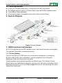
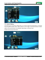
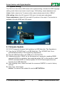
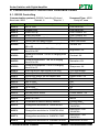
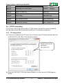
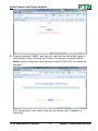
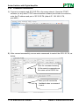
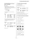
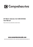
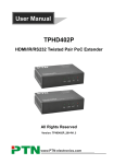
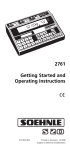
Scaler Switcher with Digital Amplifier USER MANUAL SC121D-TN PTN Scaler Switcher with Digital Amplifier Version: SC121D-TN2013V1.2 PTN Electronics Limited www.PTN-electronics.com Scaler Switcher with Digital Amplifier NOTICE: Please read this user manual carefully before using this product. This is a manual for scaler switcher SC121D-TN. This manual is only an instruction for operators, not for any maintenance usage. The functions described in this version are updated till November, 2012. Any changes of functions and parameters since then will be informed separately. Please refer to the dealers for the latest details. This manual is copyright PTN Electronics Limited. All rights reserved. No part of this publication may be copied or reproduced without the prior written consent of PTN Electronics Limited. All product function is valid till 2013-05-27. Update History Version 1.0 1.1 1.2 Date 2011.10.05 2012.11.23 2013.05.27 PTN Electronics Limited Update Content First version. Add output adjustment function and OSD introduction. Modified the system diagram. www.PTN-electronics.com Scaler Switcher with Digital Amplifier Table of Contents 1. Introduction ...............................................................................................................1 1.1. Introduction to SC121D-TN............................................................................ 1 1.2. Package Contents ......................................................................................... 1 2. Features ....................................................................................................................1 3. Specification ..............................................................................................................2 4. Operations of the Control Panel and the Remote Controller .....................................3 4.1. Operations of the Control Panel..................................................................... 3 4.2. Operations of the Remote Controller ............................................................. 4 5. Interfaces Connection Introduction............................................................................5 5.1. Video Input/output .......................................................................................... 5 5.1.1. C-Video and S-Video input ....................................................................5 5.1.2. YPbPr input ...........................................................................................5 5.1.3. VGA input ..............................................................................................6 5.1.4. HDMI input ............................................................................................6 5.2. Audio input/output .......................................................................................... 7 6. System Diagram........................................................................................................7 7. OSD Functions Introduction ......................................................................................7 7.1. Picture Setting ............................................................................................... 7 7.2. Audio Setting ................................................................................................. 8 7.3. System Setting............................................................................................... 9 8. Firmware Update.......................................................................................................9 9. Communication Protocol and Command Codes ..................................................... 10 9.1. RS232 Controlling........................................................................................ 10 9.2. TCP/IP Controlling ....................................................................................... 12 9.2.1. IP Configuration ................................................................................... 12 9.2.2. Connection Introduction.......................................................................14 10. Troubleshooting & Maintenance .............................................................................. 15 11. Safety Operation Guide ........................................................................................... 16 12. After-sales Service ..................................................................................................17 PTN Electronics Limited www.PTN-electronics.com Scaler Switcher with Digital Amplifier 1. Introduction 1.1. Introduction to SC121D-TN SC121D-TN is a full HD scaler switcher with 12 video, 6 audio & 2 MIC inputs. It scales & switches any video signal HDMI, VGA, YPbPr, C-Video & S-video to HDBaseT, HDMI & VGA simultaneously, and any audio to 2x20W amplifier. It’s controllable via the button, IR, RS232 & TCP/IP. It’s a high performance scaler for education institution, meeting room, conference room, demonstration hall etc. 1.2. Package Contents 1 x SC121D-TN 1 x TP402R (2 mounting ears & 4 screws) 1 x Power Cord 1 x Power Adapter (DC 5V) 1 x IR remote (Cell battery is not included) 4 x Captive screw connectors 4 x Plastic cushions 1 x RS232 cable 1 x User Manual Notes:Please confirm if the product and the accessories are all included, if not, please contact with the dealers. 2. Features 12 video Inputs: 4 x HDMI, 4 x VGA, 1 x YPbPr, 2 x C-video & 1 x S-video. 2 MIC inputs with level control and mixer function. Upscale to outputs HDBaseT, HDMI & VGA simultaneously up to 1080P. HDBaseT output to be paired with transmitter TPHD402R for 70M transmission. Built-in 2x20Watt@4Ω digital amplifier (or 2x10Watt@8Ω). Output resolutions selectable to assure preferred output. Output display H/V size: adjustable to settle any overscale problem. Output display H/V position moveable. MIC volume and line volume adjustable. Video parameter setting and preset. Powerful OSD function with full control. Ultra-switching for instaneous display. HDMI1.3 and HDCP compliant. Firmware updatable via USB. Output freeze function. Front panel lockout. Controllable via transmitter TPHD402R at display end. Controllable via button, IR, RS232 & TCP/IP. PTN Electronics Limited 1 www.PTN-electronics.com Scaler Switcher with Digital Amplifier 3. Specification Video Input Input Input Connector Video Signal Video Output 4 HDMI 4 VGA 1 YPbPr 2 C-Video 1 S-Video HDMI female connector VGA(15 pin HD), female connector RCA female connector 4 pin mini DIN connector HDMI 1.3, RGBHV, RGBs, RGsB, RsBsGs, NTSC 3.58, NTSC 4.42,PAL,SECAM Output 1 HDMI 1 VGA 1 HDMI TP Output Connector HDMI female connector VGA(15 pin HD), female connector RJ-45 connector Video Signal HDMI 1.3 VGA HDBase-T Bandwidth HDMI: 4.95Gbps(1.65Gbps per color) C-Video/S-Video: 150MHz YPbPr: 170MHz VGA: 375MHz Video General Resolution Range Maximum Pixel Clock Gain HDCP managemen t Audio Input 1080P,1920*1080 ; HD, 1360*768 720P, 1280*720; WXGA,1280*800 ; XGA, 1024*768. 145MHz 0dB Video Impedance I/O Level 75Ω 0.5V~2.0Vp-p Compliant with High-bandwidth Digital Content Protection(HDCP) with DVI & HDMI 1.3 standards Audio Output Input 6 Stereo Audio for line audio 2 MIC audio Output Stereo audio for line audio 2x10W@8Ω/2x20W@4 Ωamplifier Input Connector 4 RCA female connector for YPbPr, C-Video & S-Video audio 4 3.5mm jack for VGA Output Connector RCA connector Amplifier connector PTN Electronics Limited 2 www.PTN-electronics.com Scaler Switcher with Digital Amplifier audio HDMI for HDMI embedded audio Audio Input Impedance >10kΩ Audio Output Impedance 50Ω Stereo Channel Separation >80dB @1KHz Pin Configuratio ns 2 = TX, 3 = RX, 5 = GND Audio General CMRR >90dB @20Hz to 20K Hz Frequency 20Hz~20K Hz Response Control Parts Control/Rem ote IR remote, Buttons & RS-232, TCP/IP General Temperature -20 ~ +70℃ Power Supply 100VAC ~ 240VAC, 50/60Hz Case Dimension W483 x H44x D235mm Humidity Power Consumptio n Product Weight 10% ~ 90% 65W 2.1Kg 4. Operations of the Control Panel and the Remote Controller 4.1. Operations of the Control Panel ① ② ③ ④ Power indicating LED. It will keep on red when the unit is connected with power. IR sensor. It is for IR remote controlling, receiving the signal of IR remote. Signal indicating LED. Video source selection buttons. You can select video/audio sources by these buttons. And VEDIO source including three different signal: YPbPr, C-Video and S-Video. ⑤ Signal channel selection buttons. PTN Electronics Limited 3 www.PTN-electronics.com Scaler Switcher with Digital Amplifier ⑥ Resolution selection buttons. These including 1024×768, 1280x720p, 1280×800, 1360×768, 1920×1080p. ⑦ MIC volume control buttons. “MUTE” for mute MIC volume, “△”for MIC volume up, “▽”for MIC volume down, loop controlling. ⑧ Line volume control buttons. “MUTE” for mute line volume, “△”for line volume up, “▽”for line volume down, loop controlling. 4.2. Operations of the Remote Controller Source select area, 12 channels for inputs, including: Line volume control area, can work when not in MENU mode. 4 HDMI 4 VGA 2 C-VIDEO 1 S-Video Menu/ Volume control area, MUTE for line and MIC audio mute. 1 YPbPr Output resolution select area, five different resolutions can be selected, including: Direction and OK buttons area, these buttons are available only in MENU mode. 720P: 1280x720 1080P: 1920x1080 XGA: 1024x768 MIC volume control area, can work when not in MENU mode. PTN Electronics Limited WXGA: 1280x800 HD: 1360x768 4 www.PTN-electronics.com Scaler Switcher with Digital Amplifier 5. Interfaces Connection Introduction ① Two RCA connectors for stereo audio output, one VGA output, one HDMI output with audio embedded, one TP port for HDMI extending (works with PTN TPHD402R). ② Four VGA connectors for VGA inputs. ③ Four HDMI connectors for HDMI inputs. ④ Four 3.5mm audio connectors for VGA audio inputs. ⑤ One Component video input: Y/Pb/Pr, two composite video inputs: C-Video, one Separate video input: S-Video, two pairs L/R for analog audio input. ⑥ One RS232 port for series control, one USB port for firmware update. ⑦ Two MIC connectors: MIC with pre-amplification, LINE for audio direct input. One TCP/IP port for network controlling. ⑧ Amplifier with 2x10W@8Ω output. ⑨ Connector for POWER. ⑩ Grounding protection. 5.1. Video Input/output SC121D-TN supports different kinds of video signal, such as C-Video, S-Video, YPbPr, VGA, and HDMI. And all can be scaled to high-resolution HDMI & VGA format and switched out. 5.1.1. C-Video and S-Video input Supporting PAL/SECAM/NTSC format Changeable aspect ratio. (Full-screen, wide screen, 4:3) Color RGB adjustable 5.1.2. YPbPr input Input Resolution 720×480 I 720×480 P 720×576 I 720×576 P 1280×720P Frame frequency 2:1 1:1 2:1 1:1 1:1 525 525 625 625 750 PTN Electronics Limited Display Parameter Frame frequency 15.75 60 31.5 60 15.625 50 31.25 50 45 60 5 Frame frequency 4:3 4:3 4:3 4:3 16:9 www.PTN-electronics.com Scaler Switcher with Digital Amplifier 1280×720P 1920×1080 I 1920×1080 I 1920×1080 I 1920×1080 p 1920×1080 p 1:1 2:1 2:1 2:1 1:1 1:1 750 37.50 1125 28.125 1125 33.75 1250 31.25 1250 62.5 1250 67.5 The bandwidth is up to170MHz 50 50 60 50 50 60 16:9 16:9 16:9 16:9 16:9 16:9 Changeable aspect ratio. (Full-screen, wide screen, 4:3, auto-adjust) Supporting HDTV input 5.1.3. VGA input The VGA resolution is VESA standard, supporting: No. 1 2 3 4 5 6 7 Resolution 640×480@60 Hz 640×480@72 Hz 720×400@70 Hz 800×600@60 Hz 800×600@72 Hz 800×600@75 Hz 1024×768@60 Hz No. 8 9 10 11 12 13 Resolution 1024×768@70 Hz 1024×768@75 Hz 1280×1024@75 Hz 1280×768 1360×768@60 Hz 1920×1080 The bandwidth is up to 375MHz. The following audio can adjust bass/treble Changeable aspect ratio. (Full-screen, 4:3) 5.1.4. HDMI input HDMI resolution support: No. 1 2 3 4 5 6 7 8 Resolution 640×480@60Hz 640×480@72Hz 640×480@75Hz 800×600@56Hz 800×600@60 Hz 800×600@72 Hz 800×600@75Hz 1024×768@60 Hz No. 9 10 11 12 13 14 15 Resolution 1024×768@70 Hz 1024×768@75 Hz 1280×1024@75Hz 1360×768 1920×540 1920×1080I 1920×1080P Digital embedded audio decoding. Changeable aspect ratio (Full-screen, wide screen, 4:3, auto-adjust). Support HDCP1.3, compatible with DVI signal. PTN Electronics Limited 6 www.PTN-electronics.com Scaler Switcher with Digital Amplifier 5.2. Audio input/output 2 pairs of L/R analog audio input, 4 VGA audio and 2 MIC audio inputs 2x10W@8Ω amplifier output. L/R stereo audio output and HDMI embedded audio. Volume/Bass/Treble adjustable Audio status presets, changeable scene mode (Wall-mounted, Desk) 6. System Diagram Figure 2 System Diagram 7. OSD Functions Introduction SC121D-TN provides a nice OSD operation menu, with various functions and language. The operation introduction is showed as follows. 7.1. Picture Setting The first icon from left of OSD menu is to set the picture parameter. It includes the pictures mode preset, color temperature, contrast, brightness, hue, saturation, sharpness, scale, and Advance picture adjust. Some parameters are available depending on different input. The Advance Picture Adjust can set the Digital Noise Reduction, dynamic color, skin tone and Adaptive Luma adjustment function on or off. And DNR is suggested to be on, this can make the output image clear and smooth. PTN Electronics Limited 7 www.PTN-electronics.com Scaler Switcher with Digital Amplifier Please check the picture below: 7.2. Audio Setting The Second icon from left of OSD menu is to set the audio/sound parameter. It includes the sound effect preset, bass, treble, balance, scene mode, surround and smart volume setting. Some parameters are available depending on different input. Please check the picture below: PTN Electronics Limited 8 www.PTN-electronics.com Scaler Switcher with Digital Amplifier 7.3. System Setting The Third icon from left of OSD menu is the system setting, includes the OSD language setting, audio listen only, freeze output image, VGA setting, output adjustment etc. Listen: Audio output only. To resume video output, please press button “MENU”. VGA setting: Adjust the H/V signal of VGA input, includes auto adjustment. Output adjustment: Adjust H/V size and H/V position of the output. This function is available only with HDMI and VGA inputs. 8. Firmware Update SC121D-TN supports firmware field-updating, by USB flash disk. The Operation is: 1) Copy the file “MT23ATV.bin” to a USB flash disk. (The “MT23ATV.bin” file is provided/authorized by PTN engineering department) 2) Plug the USB flash disk to the USB port on SC121D-TN. 3) Pressing the button “HDMI” on the front panel for 6 seconds or sending RS232 command 0698% for updating, then press the button “OK” on the remote or send RS232 command 0609% to confirm update. SC121D-TN will capture the new firmware from USB flash disk. 4) After updating finish, reboot and send the command “0617%” to reset to factory settings. 5) After reset, reboot again. Notice: The name of the update file must be MT23ATV.bin. PTN Electronics Limited 9 www.PTN-electronics.com Scaler Switcher with Digital Amplifier 9. Communication Protocol and Command Codes 9.1. RS232 Controlling Communication protocol: RS232 Controlling Protocol Baud rate: 9600 Data bit: 8 Stop bit: 1 Command 0600% 0601% 0602% 0603% 0604% 0605% 0606% 0607% 0608% 0609% 0610% 0611% 0612% 0613% 0614% 0615% 0616% 0617% Function Description MUTE Line UnMute Line Audio turn up Audio turn down Lock the front panel button Unlock the front panel button Preset the volume. The XX is ranging from 00 to 99 Preset the brightness. The XX is ranging from 00 to 99 Preset the contrast. The XX is ranging from 00 to 99 Preset the saturation. The XX is ranging from 00 to 99 Preset the sharpness. The XX is ranging from 00 to 07 Auto-adjust the input signal(VGA only) Auto-adjust the color temperature ZOOM the image, set the aspect ratio OK, for OSD selection Left of OSD Right of OSD Up of OSD Down of OSD Set the picture mode SM Mode MENU of OSD Command to reset to factory defaults 0618% Change the resolution to 1360X768 HD 0626% Change the resolution to 1024X768 XGA 0627% Change the resolution to 1280X720 720P 0628% Change the resolution to 1280X800 WXGA 01XX% 02XX% 03XX% 04XX% 05XX% PTN Electronics Limited 10 Command Type: ASCII Parity bit: none Feedback Example LINE Mute On LINE Mute Off LINE Volume: XX LINE Volume: XX Panel Locked Panel UnLocked Volume: XX Brightness: XX Contrast: XX Saturation: XX Sharpness: XX VGA Adjustment Color Temp: XX Aspect Ratio: XX OK Left Right Up Down Picture Mode : XX Sound Mode: XX MENU Factory reset Resolution: HD 1360X768 Resolution: XGA 1024X768 Resolution: 720P 1280X720 Resolution: WXGA www.PTN-electronics.com Scaler Switcher with Digital Amplifier 0629% Change the resolution to 1920X1080 1080P 0630% Check the volume level 0631% Check the input source 0632% Check the output resolution 0633% 0634% 0635% 0636% 0637% 0638% 0639% 0640% 0644% Check the image mode Check the audio mode Check the image aspec ratio Check the brightness Check the contrast Check the saturation Check the sharpness Check the color temperature OSD CHANNEL display able 0645% Shield OSD CHANNEL 0646% 0647% Volume Bar display able Volume Bar display unable 0648% Digital audio (HDMI and SPDIF) output able 0650% 0651% Shield digital audio (HDMI and SPDIF) output Check OSD CHANNEL display status Check Volume Bar display status 0652% Check Digital audio output status 0655% 0656% 0698% 0701% 0702% 0703% 0704% 0705% 0706% 0707% 0708% 0709% Freeze output image Cancel the freezing of output image Firmware update Switching to HDMI1 input Switching to HDMI2 input Switching to HDMI3 input Switching to HDMI4 input Switching to VGA1 input Switching to VGA2 input Switching to VGA3 input Switching to VGA4 input Switching to composite video AV1 input 0649% PTN Electronics Limited 11 1280X800 Resolution: 1080P 1920X1080 LINE Volume: XX/MIC Volume: XX Source: XXXXXX Resolution: XXXXXXXX Picture Mode : XX Sound Mode: XX Aspect Ratio: XX Brightness: XX Contrast: XX Saturation: XX Sharpness: XX Color Temp: XX OSD Source: Display OSD Channel (Source): No Display Volume Bar: Display Volume Bar: No Display Digital Sound Ouput: Enable Digital Sound Ouput: Disable OSD Source: Display Volume Bar: Display Digital Sound Ouput: Enable Freeze: Enable Freeze: Disable Source: Source: Source: Source: Source: Source: Source: Source: Source: HDMI 1 HDMI 2 HDMI 3 HDMI 4 VGA1 VGA2 VGA3 VGA4 CVIDEO1 www.PTN-electronics.com Scaler Switcher with Digital Amplifier 0710% 0711% 0712% 0720% 0721% 0722% 0723% 0724% 0725% 08XX% Switching to YPbPr input Switching to S-Video input Switching to composite video AV2 input Mute Line and MIC UnMute Line and MIC MUTE MIC UnMute MIC MIC volume turn up MIC volume turn down Preset MIC volume Source: YPbPr Source: SVIDEO Source: CVIDEO2 Mute On Mute Off MIC Mute On MIC Mute Off MIC Volume: XX MIC Volume: XX MIC Volume: XX 9.2. TCP/IP Controlling The TP port of SC121D-TN is used for TCP/IP control. And all the control commands are the same as the RS232 command list.Below is the detailed introduction. 9.2.1. IP Configuration 1) Connect a computer to the TP port, set its IP to the same IP section as the default IP of SC121D-TN (192.168.0.178). As picture below: Same IP section but cannot be 192.168.0.178 2) Enter the 192.168.0.178 to the Internet Explore, you will see the LOGIN page as below: PTN Electronics Limited 12 www.PTN-electronics.com Scaler Switcher with Digital Amplifier 3) Enter the password “88888”, and then you can enter the configuration page to configure the IP port, including the IP reset, PW reset etc. As picture below: Notice: Serial configuration must be fixed to meet SC121D-TN, so it cannot be changed. After configuration, reset device, then you can use the new IP address for controlling. PTN Electronics Limited 13 www.PTN-electronics.com Scaler Switcher with Digital Amplifier 9.2.2. Connection Introduction 1) Connect a computer and SC121D-TN to the same network. Open the PTNET software (or any other TCP/IP communication software) and create a connection, enter the IP address and port of SC121D-TN (default IP: 192.168.0.178, port:4001): 2) After connect successfully, we can enter commands to control the SC121D-TN, as below: Here for command entering. All the control commands are the same as the RS232 list. Here you will receive the feedback when a command is sent. PTN Electronics Limited 14 www.PTN-electronics.com Scaler Switcher with Digital Amplifier 10. Troubleshooting & Maintenance 1) When images of terminal unit output with ghost, such as the projector output with ghost. Please check the projector’s setting or try another high quality connection cable. 2) When there is a color losing or no video signal output, please check the input and output end connections of the cables. 3) When the remote controller doesn’t works: The battery has no power, please change a new one. The controller was broken, please repair it. 4) When user cannot control the switcher by computer through its COM port, please check the COM port number in the software and make sure the COM port is in good condition. 5) When there is no output images: Check if there is any signal at the input. Check if there is any signal at the output. We can check these by using an oscilloscope or a multimeter. If there is no signal input/output, maybe the input/output cables broken or the connectors loosen, please change for another cable. If not the problem mentioned above, probably there is something broken inside the unit, please send it to the dealer for repairing. 6) If the POWER indicator doesn’t work or no respond to any operation, please make sure the power cord connection is good. 7) If the output image is interfered, please make sure the system is grounded well. 8) If the static becomes stronger when connecting the BNC connectors, it probably due to the incorrect grounding, please correct it otherwise it would damage the switcher. 9) If the switcher cannot be controlled by the buttons on the front panel, RS232 port or IR remote, the switcher may have broken. Please send it to the dealer for repairing. PTN Electronics Limited 15 www.PTN-electronics.com Scaler Switcher with Digital Amplifier 11. Safety Operation Guide In order to guarantee the reliable operation of the equipments and safety of the staff, please abide by the following proceeding in installation, using and maintenance: 1) The system must be earthed properly. Please do not use two blades plugs and ensure the alternating power supply ranged from 100v to 240v and from 50Hz to 60Hz. 2) Do not put the switcher in a place of too hot or too cold. 3) As the power generating heat when running, the working environment should be maintained fine ventilation, in case of damage caused by overheat. 4) Cut off the general power switch in humid weather or left unused for long time. 5) Before following operation, ensure that the alternating current wire is pull out of the power supply: Take off or reship any components of the equipment. Take off or rejoin any pin or other link of the equipment. 6) As to non-professional or without permission, please DO NOT try to open the casing of the equipment, DO NOT repair it on your own, in case of accident or increasing the damage of the equipment. 7) DO NOT splash any chemistry substance or liquid in the equipment or around. PTN Electronics Limited 16 www.PTN-electronics.com Scaler Switcher with Digital Amplifier 12. After-sales Service 1) If there appear some problems when running SC121D-TN, please check and deal with the problems reference to this user manual. Any transport costs are borne by the users during the warranty. 2) You can email to our after-sales department or make a call, please tell us the following information about your cases. Product version and name. Detailed failure situations. The formation of the cases. 3) We offer products for all three-year warranty, which starts from the first day you buy this product (The purchase invoice shall prevail). 4) Any problem is same with one of the following cases listed, we will not offer warranty service but offer for charge. Beyond the warranty. Damage due to incorrectly usage, keeping or repairing. Damage due to device assembly operations by the maintenance company non-assigned. No certificate or invoice as the proof of warranty. The product model showed on the warranty card does not match with the model of the product for repairing or had been altered. Damage caused by force majeure. Remarks: For any questions or problems, please try to get help from your local distributor, or email PTN at: [email protected]. PTN Electronics Limited 17 www.PTN-electronics.com