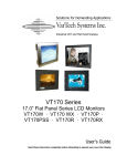
1
Solutions for Demanding Applications
VarTech Systems Inc.
Industrial CRT and Flat Panel Displays
Chassis Mount Series
Flat Panel LCD Monitors
VT064C · VT104C · VT121C
VT064CHB · VT104CHB
User’s Guide
Read these instructions completely before attempting to operate your new Color Display.
Table Of Contents
Section 1
Page Section 4
Introduction
Page
Touch screen
About LCD Monitors
1
Touch Screen Introduction
11
Product Safety Precautions
2
Touch Screen Definition
On Safety
2
Touch Screen Serial Interface
12
On Installation
3
Setting up the Touch Interface
12
On Cleaning
3
Installing Windows NT 4.0 Touch Drivers
13
On Repacking
3
Installing Windows 95/98 Touch Drivers
13-14
Installing Windows 2000 Touch Drivers
14
11-12
Section 2
Display Setup
Section 5
Display Features
4
Unpacking The Display
4
Included Parts
4
Section 6
Connecting Your Display
5
Cleaning & Maintenance
Signal Connections
Troubleshooting Tips
15-16
17
5-6
Section 7
Section 3
Mechanical Drawings
18
Getting Started
VT064C Mechanical
19
VT104C Mechanical
20
OSD On-Screen Display
7-8
OSD Functions
9-10
Section 8
Specifications
6.4” Specifications
21
10.4” Specifications
22
12.1” Specifications
23
Section
1
INTRODUCTION
About LCD Monitors
What you gain by using an LCD monitor in your industrial controls
LCDs
are the future of display technology. CRTs, although they have dropped in
cost significantly, do not offer the performance, reliability, and mounting
options available with LCDs. LCD monitors consist primarily of an LCD, Video
Board and a Back Light video. The LCD determines to a large extent the
viewing angle, brightness and contrast. Beyond that it is the function of the video board which converts
the analog RGB (Red, Green, Blue) signals from a standard video card to a high quality, digital RGB that
the LCD can display.
Recently the video card has taken on a new role. It is the responsibility of this device to “scale” a
particular video resolution to the “native” resolution of the LCD. Simply, consider that a computer is
putting out a VGA [640x480] resolution signal, yet the LCD that is connected is an XGA [1024x768]
display. The displayed picture would be in the center 1/3 of the LCD. With the introduction of the scaling
engine. The converter will mathematically recalculate the 640x480 to 1024x768. This may sound simple
but it is in fact a complex algorithm that adjusts for different aspect ratios and pixel alignment, essentially
smoothing text and graphics to produce a picture that is pleasant to the eye.
1
Product Safety Precautions
This unit has been engineered and manufactured to ensure your personal safety, however
improper use may result in potential electrical shock or fire hazards. In order to allow the
proper operation of all safeguards incorporated in this display, observe the following basic
rules for its installation, use, and servicing.
On Safety
Use only the power cord supplied with the unit. In case you use another power cord, make sure that
it is certified by the applicable national standards if not being provided by the supplier. If the power
cable is faulty in any way, please contact the manufacturer or the nearest authorized repair service
provider for a replacement. The power supply cord is used as the main disconnection device.
Ensure that them socket-outlet is easily accessible after installation. Operate the display only from a
power source indicated in the specifications of this manual or listed on the display. If you are not
sure what type of power supply you have, consult with your service or maintenance department.
Overloaded AC outlets and extension cords are dangerous. So are frayed power cords and broken
plugs. They may result in a shock or fire hazard Call your service technician for replacement.
Do not Open the Display.
♦ There are no user serviceable components inside.
♦ There are Dangerous High Voltages inside, even when the power is OFF.
♦ Contact your dealer if the display is not operating properly.
To Avoid Personal Injury :
♦ Do not place the display on a sloping shelf unless properly secured.
♦ Use only a stand recommended by the manufacturer.
♦ Do not try to roll a stand with small casters across thresholds or deep pile carpets.
To Prevent Fire or Hazards:
♦ Always turn the display OFF if you leave the area for more than a short period of time.
♦ Do not drop or push objects into the display's cabinet openings. Some internal parts carry
hazardous voltages.
♦ Do not add accessories that have not been designed for this display.
♦ During a lightning storm or when the display is to be left unattended for an extended period of
time, unplug it from the wall outlet.
Important Precautions
2
On Installation
Do not allow anything to rest upon or roll over the power cord, and do not place
the display where the power cord is subject to damage.
Do not use this display near water such as near a sink, in a wet location where there is standing
water. Displays are provided with ventilation openings in the cabinet to allow the release of heat
generated during operation. If these openings are blocked, built-up heat can cause failures which
may result in a fire hazard.
Therefore, NEVER:
♦ Block any ventilation slots.
♦ Place the display in a built-in enclosure unless proper ventilation is provided.
♦ Cover the openings with cloth or other material.
♦ Place the display near or over a heat source.
Do not rub or strike the Active Matrix LCD with anything hard as this may scratch,
mar, or damage the Active Matrix LCD permanently.
Do not press the LCD screen with your finger for a long time as this may cause
some afterimages.
Some dot defects may appear as Red, Green or Blue spots on the screen.
However, this will have no impact or effect on the display performance.
If possible, use the recommended resolution to obtain the best image quality for
your LCD display. If used under any mode except the recommended resolution,
some scaled or processed images may appear on the screen. However, this is
characteristic of the fixed-resolution LCD panel.
On Cleaning
Unplug the display before cleaning the face of the display screen. Use a 50/50 mix of Isopropyl
alcohol and water. Apply with a slightly damp (not wet) lint free cloth. Do not use an aerosol directly
on the display screen because over-spraying may cause electrical shock.
On Repacking
Do not throw away the carton and packing materials. They make an ideal container in which to
transport the unit. When shipping the unit to another location, repack it in its original material.
3
Section
DISPLAY SETUP
2
Chassis Mount Series Display Features
⇒
Capable of displaying unlimited colors in a continuous spectrum. The high contrast LCD enhances the
image with no geometric distortion.
⇒
The Chassis Mount Series is supplied with a Anti-Reflective Screen unless equipped with an optional
Touch System.
⇒
The Chassis Mount Series requires 12VDC supply input.
Unpacking and setting up your display
Your LCD monitor package will consist of the components listed below. Open shipping container and
lay all components on a flat clean surface.
What is included with your display
⇒
⇒
⇒
⇒
⇒
⇒
VT064C, VT104C or VT121C LCD Monitor
5 ft Video Cable (HD15(M) - HD15(M))
6 ft RS232 Touch Interface Cable (Optional when touch is installed)
CD ROM with Touch Screen Drivers (Optional when touch is installed)
Power Supply, AC to 12VDC (optional)
Users Guide (Printed or on CD)
4
Connecting the Display
1. Connect all cables to the computer first. This would include the VGA cable and the optional RS
232 serial touch screen connection.
2. After connecting the cables between the LCD monitor and the computer, plug the power cord into
the 115/220VAC power outlet if using using the optional AC to 12VDC power supply.
3. Once the 115/220VAC connection is made, the display is active.
4. If your computer was off, turn on your computer.
5. Your display should now operate as a normal computer display showing your windows or
whatever video is being sent to the flat panel.
Note:
If for any reason the display goes blank and gives an “out of Range” or “No Sync”, your computer
or video source is putting out a signal that is out of range of the LCD’s video board. If this happens,
reboot the computer or video source and make sure you are inputting the correct signal. If the display doesn’t work properly, it may be because:
The resolution is to high or low for the LCD.
(a) The refresh rate is set to high. Refresh on an LCD is different than a CRT. Set the refresh to
60Hz. CRT’s need a high refresh rate to avoid flicker. The refresh rate has no impact on LCD’s.
(b) The power source is incorrect.
(c) The unit is malfunctioning. If you believe this to be true, disconnect the video cable from the rear
of the LCD and connect to a known good computer CRT display. If the computer display is
working satisfactory and the video is within the appropriate range, then contact VarTech
Customer service for a RMA number.
5
Signal Connections
To avoid irregular operation and /or damage to the display, please insure correct video is being
supplied as shown on the following page.
HD15(F) Connector
HD-15 Video Connector
Pin
Signal
Pin
Signal
Pin
Signal
1
Red Video
6
Ground
11 Not Used
2
Green Video
7
Ground
12 DDC Data
3
Blue Video
8
Ground
13 Analog H Sync
4
Not Used
9
Fused VCC
14 Analog V Sync
5
Ground
10 Ground
15 DDC Clock
C-Video Connector
S-Video Connector
C-Video Connector
S-Video Connector
Pin Signal
Pin
Signal
1
Ground
1
Ground
2
Ground
2
Composite video signal
3
Luminance
4
Chorminance
6
Section
3
Getting Started
3.1 OSD - On Screen Display
The OSD allows selection of input source and fine tuning of various functional parameters
like brightness, phase etc. These parameters can be adjusted via push buttons. Visual
feedback is provided in the form of an On-Screen-Menu. The OSD Controls are located on
the rear of the display.
The 4 buttons of OSD control can either be used to navigate within the OSD functions see table 2.
For direct call of some special functions see table 1.
7
3.1 OSD - On Screen Display Cont.
Table 1
NO.
Button name
Switch Function
1
Power
---
2
Menu
---
3
Select
Auto Adjust
4
Up
Reset and Auto Adjust
Table 2
NO.
Button
name
Switch Function
1
Power
Switch on / off Power
2
Menu
1. First Click: Activate the OSD Main Menu
2. Second Click: Deactivate the OSD Main Menu
3. Leave Sub-Menu / back to Main Menu
3
Select
Select the value of OSD Main Menu or value of OSD
Sub-Menu and change the value of OSD sub-menu to be
able to modify (toggle key)
4
Up
1. Move between Main Menu
2. Move between Sub-Menu inside Main Menu
3. Adjustment of Sub-Menu value inside Main Menu
5
Down
1. Move between Main Menu
2. Move between Sub-Menu inside Main Menu
3. Adjustment of Sub-Menu value inside Main Menu
8
3.2 OSD Functions
The Main Menu had 14 different functions. Some of these functions have Sub-Menus
OSD Agent
Description
Brightness Control
Adjusts the brightness of video without affecting
PC RGB’s brightness.
Black Level
Adjusts the brightness of the display backlight.
Contrast
Adjusts the contrast of video without affecting PC
RGB’s Contrast.
Color
Changes the richness of the color.
9
3.2 OSD Functions Cont.
The Main Menu had 14 different functions. Some of these functions have Sub-Menus
OSD Agent
Description
Image Position
Adjusts the horizontal and vertical position of the
display.
Image Phase / Clock
Removes the noises. When frequency value is
wrong, the image has horizontal lines.
Auto Configuration
Automatically adjusts display for best picture.
Information
Displays current display mode.
Miscellaneous Factory
Adjusts the OSD duration and positioning
Reset
Input Select
To select analog, s-video, composite
Video Hue
Adjusts the Hue and Saturation levels
YUV Color Brightness
Adjusts the brightness, black level, contrast,
saturation, hue, fleshtone.
Gamma Moire
Adjusts the video gamma and moiré for best
display.
Save Changes
Save OSD changes per adjusted set-up.
10
Section
Touch Screen
4
4.1 Touch Screen Introduction
Touch screen interfaces have become the standard interface in the past 5 years. They are,
rugged, reliable, extremely flexible and easier than ever to implement! Over 90% of the
display packages Vartech Systems builds are touch screen systems. If you are uncertain
about using a touch screen, or are having difficulty, please call us. The universal acceptance
of the Windows GUI [Graphical User Interface] along with the extensive use of a mouse
interface has significantly accelerated the use of touch interface. Basically think of your touch
screen as if it were a mouse.
4.2 Touch Screen Definition
Quite simply, Vartech Systems touch systems are a mouse emulator. By installing a software
driver and connecting to a serial port, the touch screen will support all the primary mouse
functions:
Our standard touch screen interface, is a high resolution analog resistive. Following is a quick
explanation of what all this means.
High Resolution: The touch screen resolution is 400 ppi [points per inch]
Analog Resistive: The actual touch glass is an analog device. Meaning there is a very low
voltage applied to the X and Y axis of the touch screen. This current is applied to ITO [Iridium
Tin Oxide] that is sputtered onto a polyester membrane. When you touch the screen you are
changing the resistance on both the X and Y axis, producing an analog value that references
a particular location.
This type of screen can be activated with a gloved finger or mechanical stylus.
The touch screen itself is connected to electronics that provide the Analog to Digital
conversion. When the screen is touched, the electronics convert the analog voltage to a
digital value and add a “Mouse Click”, then sends the data to the serial port that the driver is
loaded to. When the touch is released the new XY location is sent along with a “Mouse Up
Click”.
This system requires no special software knowledge, and can be installed and set up in
minutes. The following section gives a detailed explanation of the software setup and
configuration.
Since the touch screen interface is RS-232, the recommend maximum distance from the PC
is 50 feet. In reality, every application is different. The touch driver default baud rate is 9600,
and we have tested the driver and interface with good quality cables to 50 feet. With RS-232
line drivers this can be extended almost indefinitely.
11
4.2 Touch Screen Definition Cont.
Connecting the touch screen
1. Make sure all optional cables have been received.
2. Connect one end of the 6 foot touch screen serial cable to the touch screen port D9 connector on the side of the monitor.
3. Connect the other end to any communications port on the host computer.
4. Tighten the captive screws on the cable connector to secure it.
4.3 Touch Screen Serial Interface
All touch controllers are configured by default to provide serial communications at 9600 baud, 8 data
bits, 1 stop bit, no parity. For Vartech flat panels equipped with touch screens, a serial
communications cable is required. This 6 foot cable comes with the unit in the accessory kit.
The cable is a straight wired serial (RS-232) cable with a male DE-9 D-shell connector on the
monitor end. The cable provides a communications channel between the touch screen
controller, which is mounted inside the monitor, and an RS-232 serial port on the host computer.
Because the touch controller obtains power from the monitor's power supply, no external touch power
connections are necessary.
Software supplied with the touch screen must be loaded on the host computer to handle
communications with the touch controller over the channel.
Because the touch screen emulates a mouse, there may be compatibility issues involving how the
touch screen emulates mouse buttons, especially multiple buttons.
4.4 Setting up the Touch Screen Interface
Enabling the Touch Screen Interface
The Flat Panel Monitor provides a female DE-9 connector for the touch interface.
This connector provides the serial interface for the touch controller.
Interconnecting wiring to the host serial port connection is shown in the following table.
Touch screen Interface
Monitor
(DCE Device)
DE-9 (Female)
1
2
3
4
5
6
7
8
9
Signal Description
Not Connected (DCD)
Transmit Data (TXD)
Receive Data (RXD)
Data Terminal Ready (DTR)
Common Signal Return (SG)
Not Connected (DSR)
Request To Send (RTS)
Clear To Send (CTS)
Not Connected
12
Host (DTE Device)
DE-9 (Male) DB-25 (Male)
1
8
2
3
3
2
4
20
5
7
6
6
7
4
8
5
9
22
4.5 Installing Touch Screen Driver Windows NT 4.0
1. Start your computer.
2. Insert the MonitorMouse for Windows NT disk into drive A.
3. Click the Start button then click Run.
4. Type “a:\setup” in the space provided and press Enter.
5. Follow the directions on the screen.
6. MonitorMouse for Windows NT provides two Installation options. Most users
should select Typical (the default) and click Next to continue. Custom allows
you to install the sample touch screen programming files.
7. The Touch screen Setup dialog box will appear. Specify the type of
touch screen controller you are using and how it is connected. Also specify the
language you want to use in the Touch screen Control Panel. Click OK to
confirm that the Setup is correct.
8. Complete the Setup program.
9. Shutdown and restart Windows NT. Continue the steps on the next page.
10. Click the Start button, then click Settings, then click Control Panel.
11. Double-click Elo Touch screen to run the Touch screen Control Panel.
12. Click the Calibrate button and touch each of the three targets as they appear
on the screen. Touch Yes when the cursor lines up correctly with your finger.
Touch OK to close the Touch screen Control Panel.
Note:
If at any time the screen cursor is not directly under your finger on a touch, the touch screen
can be re calibrated at anytime by going to the Windows control panel and selecting the Elo
Icon and selecting Calibrate.
4.6 Installing Touch Screen Driver Windows 95/98
Start your computer.
2. Insert the MonitorMouse for Windows 95 disk into drive A.
3. Click the Start button then click Run.
4. Type “a:\setup” in the space provided and press Enter.
5. Follow the directions on the screen.
6. MonitorMouse for Windows 95 provides two installation options.
Most users should select Typical: (the default) and click Next to continue.
Custom: allows you to install the sample touch screen programming files.
7. The Touch screen Setup dialog box will appear. Specify the type of touch screen
controller you are using (Serial SmartSet Model 2210) and how it is connected. Click OK to
confirm that the Setup is correct.
8. Complete the Setup program.
9. Restart Windows 95/98.
10. Click the Start button, then click Settings, then click Control Panel.
13
4.6 Installing Touch Screen Driver Windows 95/98 Cont.
11. Double-click Elo Touch screen to run the touch screen control panel.
12. Click the Calibrate button and touch each of the three targets as they appear on the screen.
13. Click yes when the cursor lines up correctly with your finger. Click OK to close the touch screen
control panel.
Note:
If at any time the screen cursor is not directly under your finger on a touch, the touch screen can be
calibrated at anytime by going to the Windows control panel and selecting the Elo Icon and select
Calibrate.
4.7 Installing Touch Screen Driver Windows 2000
1. Start your computer.
2. Insert the MonitorMouse for Windows 2000 disk into drive A.
3. Click the Start button then click Run.
4. Type “a:\setup” in the space provided and press Enter.
5. Follow the directions on the screen.
6. MonitorMouse for Windows 2000 provides two Installation options. Most users
should select Typical (the default) and click Next to continue.
Custom allows you to install the sample touch screen programming files.
7. The Touch screen Setup dialog box will appear. Specify the type of
touch screen controller you are using and how it is connected. Also specify the
language you want to use in the Touch screen Control Panel. Click OK to
confirm that the Setup is correct.
8. Complete the Setup program.
9. Shutdown and restart Windows 2000. Continue the steps on the next page.
10. Click the Start button, then click Settings, then click Control Panel.
11. Double-click Elo Touch screen to run the Touch screen Control Panel.
12. Click the Calibrate button and touch each of the three targets as they appear
on the screen. Touch Yes when the cursor lines up correctly with your finger.
Touch OK to close the Touch screen Control Panel.
Note:
If at any time the screen cursor is not directly under your finger on a touch, the touch screen
can be re-calibrated at anytime by going to the Windows control panel and selecting the Elo
Icon and selecting Calibrate.
Note:
For latest touch information, refer to www.elotouch.com
14
Section
5
No Picture
Troubleshooting Tips
•
•
•
•
•
The signal cable should be properly connected to the display
card and computer.
Try disconnecting the video cable from the display and
connecting to a CRT display if available to confirm the
presence of proper video.
Make sure power is connected to the proper DC or AC
source.
Make sure the resolution mode is supported by the display
and check settings of the display card.
Confirm that the video cable is not defective.
Image Persistence
Image persistence occurs when a ghost of an image remains on
the screen after the monitor has been turned off. Unlike a CRT
monitor, an LCD monitor’s image persistence is not permanent.
To erase an image ghost, turn the monitor off for as long as the
image was displayed. If the image was on for one hour and the
ghost of the image remains, the display should be turned off for
one hour to erase the image. To avoid this problem, use a screen
saver.
Picture Quality & Image
Stability
•
•
•
•
Check for proper video cable for proper grounding and
shielding.
Check the signal source for proper signal.
Check for proper adjustment of the Phase and Frequency
controls.
Check for proper recommended signal timing.
Display image is not
properly sized
•
•
Adjust the Vertical and Horizontal size controls via the OSD.
(Reference setup adjustments)
Ensure that a supported mode is selected on the display card
or system being used. Consult the display card or system
manual for proper video.
No S-Video or NTSC
operation
•
•
Check for proper connections.
Check the setup instructions for proper input selection.
Screen is blank.
•
•
•
•
Screen saver activated.
Video Cable problem. Check for proper installation
Change video cable
Faulty video display. Needs Service
15
5.0 Troubleshooting Tips Cont.
Image is dim, even with brightness •
and contrast controls set full UP.
•
•
•
Video cable problem.
Check for proper installation of cables
Faulty video source
Faulty display
Image not centered
Reset the horizontal and vertical positioning using the
on-screen menu. Check to see if video source is
operating within the monitor’s range.
Image will not adjust
Video timing outside of range. Use the on-screen menu
to ad just the Clock Setting.
Make sure timing is within VESA standard.
Image is not stable.
Monitor has incorrect or bad sync signals.
Check for proper video cable installation.
Replace suspected faulty cable.
Check to ensure that video source is operating within the
display’s range.
Vertical shaded bars on screen im- Horizontal size not properly adjusted.
Adjust horizontal size settings.
age
Colors are missing
•
•
Faulty video cable.
Missing from video source. Connect video source to
another display.
Screen jitter or noisy display
•
•
•
Monitor clock phase not properly adjusted.
Video cable problem
External noise interference.
Slight distortion in text or Graphics. Not working in native resolution.
Display is present but “bars”
appear or roll across screen
Ground loop problem between computer and display
Interference from adjacent equipment.
The background looks acceptable
but text and icons seem to be
missing rows of pixels
Video running interlace mode.
If these tips do not solve your problem, contact VarTech Systems Customer Service support.
16
Section
Cleaning and Maintenance
6
Cleaning
Occasionally clean the display panel and cabinet with a soft cloth dampened (not
soaked) with a mild (non-abrasive) glass cleaner. Keep turning a fresh side of the
cloth toward the screen surface to avoid scratching it with accumulated grit.
Do not use paper products as they may scratch the surface. To minimize the risk of
abrasion, allow the screen to stand dry.
Note: The solvent (a 50/50 mixture isopropyl alcohol and water) should be applied
only to the cloth, and not directly on the monitor screen.
Special care should be taken when cleaning a touch screen or polycarbonate shield
that is installed over the screen. Abrasive and certain chemical cleaners can easily
damage the surface.
Never use alcoholic or ammoniac cleaners to clean the polycarbonate shield or a
touch screen.
Replacing a Line Cord
To avoid shock and fire hazards, the monitor’s power cord should be replaced if the
insulation becomes broken or if it develops a loose internal connection.
Other Maintenance
Qualified service personnel should perform all maintenance, except for
the power cord replacement described above.
17
Section
7
MOUNTING INSTRUCTIONS
Mechanical Drawings
Model
Description
Page(s)
VT064C
6.4” Chassis Mount Mechanical Drawing
19
VT104C
10.4” Chassis Mount Mechanical Drawing
20
18
Section
Specifications
8
6.4” Specifications
Panel Size
Type
Max. Resolution
Active Diagonal
Active Display Area
Pixel Format
Viewing Angle (Up/Down)
Viewing Angle (Left/Right)
Contrast Ratio
Brightness
Response Time
Back Lights
Video Connectors
Video Input
Sync
Colors Supported
Power Input
Power consumption
Operating Temperature
Storage Temperature
Operating Humidity
Storage Humidity
Operating Altitude
Storage Altitude
6.4”
TFT Active matrix
VGA
6.4” Viewable
5.10” (w) x 3.84” (h)
129.6mm x 97.44mm
640 x 480
110º
70º
180:1
VT064C: 300 Nits
VT064CHB: 700 Nits
TR = 30ms
TD = 50ms
20,000 Hours CCFL
25,000 MTBF
HD15(F)
RCA (NTSC)
5 Pin Mini Din (S-Video)
RGB Analog (0.7V p-p / 75ohm)
CVBS (1.0V p-p)
S-VHS, luma/chroma (.7V p-p / 75ohm)
NTSC
Separate H&V
Combined, SOG (Sync On Green)
262,000
12VDC @ 1.5A
Normal: 35 Watts @ +12V
4 Watts Sleep Mode
0 to 50ºC
-20 to 60ºC
10 to 95% NC
10 to 95% NC
Up to 10,000 ft
Up to 40,000 ft
21
10.4” Specifications
Panel Size
Type
Max. Resolution
Active Diagonal
Active Display Area
Pixel Format
Viewing Angle (Up/Down)
Viewing Angle (Left/Right)
Contrast Ratio
Brightness
Response Time
Back Lights
Video Connectors
Video Input
Sync
Colors Supported
Power Input
Power consumption
Operating Temperature
Storage Temperature
Operating Humidity
Storage Humidity
Operating Altitude
Storage Altitude
10.4”
TFT Active matrix
VGA
10.4” Viewable
8.32” (w) x 6.24” (h)
211.2mm x 158.4mm
640 x 480
110º
70º
300:1
VT104C: 380 Nits
VT104CHB: 850 Nits
TR = 15ms
TD = 35ms
40,000 Hours CCFL
25,000 MTBF
HD15(F)
RCA (NTSC)
5 Pin Mini Din (S-Video)
RGB Analog (0.7V p-p / 75ohm)
CVBS (1.0V p-p)
S-VHS, luma/chroma (.7V p-p / 75ohm)
NTSC
Separate H&V
Combined, SOG (Sync On Green)
262,000
12VDC @ 1.5A
Normal: 35 Watts @ +12V
4 Watts Sleep Mode
0 to 50ºC
-20 to 60ºC
10 to 95% NC
10 to 95% NC
Up to 10,000 ft
Up to 40,000 ft
23
12.1” Specifications
Panel Size
Type
Max. Resolution
Active Diagonal
Active Display Area
Pixel Format
Viewing Angle (Up/Down)
Viewing Angle (Left/Right)
Contrast Ratio
Brightness
Response Time
Back Lights
Video Connectors
Video Input
Sync
Colors Supported
Power Input
Power consumption
Operating Temperature
Storage Temperature
Operating Humidity
Storage Humidity
Operating Altitude
Storage Altitude
12.1”
TFT Active matrix
VGA
12.1” Viewable
9.69” (w) x 7.26” (h)
246mm x 184.5mm
640 x 480, 800 x 600
120º
90º
300:1
VT121C: 300 Nits
TR = 20ms
TD = 30ms
50,000 Hours CCFL
25,000 MTBF
HD15(F)
RCA (NTSC)
5 Pin Mini Din (S-Video)
RGB Analog (0.7V p-p / 75ohm)
CVBS (1.0V p-p)
S-VHS, luma/chroma (.7V p-p / 75ohm)
NTSC
Separate H&V
Combined, SOG (Sync On Green)
262,000
12VDC @ 1.6A
Normal: 35 Watts @ +12V
4 Watts Sleep Mode
0 to 50ºC
-20 to 60ºC
10 to 95% NC
10 to 95% NC
Up to 10,000 ft
Up to 40,000 ft
22
VARTECH SYSTEMS
HEADQUARTERS
11529 Sun Belt Ct.
Baton Rouge, Louisiana 70809
Toll-Free: 800.223.8050
International Phone: 001.225.298.0300
Fax: 225.297.2440
E-mail: [email protected]
www.vartechsystems.com
150-037-005
3.18.04