1
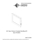
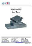
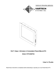
Solutions for Demanding Applications
VARTECH
SYSTEMS
I N C.
Industrial CRT and Flat Panel Displays
VT320X
Large Screen Outdoor LCD
User’s Guide
Read these instructions completely before attempting to operate your new Color Display
USER MANUAL
Contact VarTech Systems Inc.
11529 Sun Belt Ct.
Baton Rouge, LA 70809
Phone:
225.298.0300
800-223-8050
Fax:
225.297.2440
Email:
[email protected]
Website:
www.vartechsystems.com
This document contains proprietary information belonging to Vartech Systems Inc. It is supplied to
Vartech Systems Inc.l Customers on a confidential basis for their own internal use. It is not to be
released to any third party except those contracted by Vartech Systems Inc. Customers.
Vartech Systems Inc. grants permission for its customers to make copies of any information in this
publication to assist them in setting up displays. Any use, distribution or duplication other than such
internal use is prohibited. All trademarks are the property of their respective owners.
VT320X
2 of 18
150-117
Contact VarTech Systems ............................................................................................1
Chapter 1: Requirements and Specifications .........................................................3
VT320X Requirements .....................................................................................................................................3
VT320X Location Requirements: ...................................................................................................................4
VT320X Reference Tables and Figure ..........................................................................................................5
Video Display Broadcast Unit (VDBU) Requirements...................................................................................6
VDBU Reference Table and Figure ..................................................................................................................7
Chapter 2: Pre-Installation Checklists ....................................................................8
Tools Required.....................................................................................................................................................8
Miscellaneous Hardware Required .................................................................................................................8
VT320X Parts List .............................................................................................................................................8
Chapter 3: Ceiling Mount Installation .....................................................................9
Inspect PCM (Plasma Ceiling Mount) Components ......................................................................................9
Install the Ceiling Plate ......................................................................................................................................9
Assemble the PCM ...........................................................................................................................................10
Secure the PCM to the Ceiling Plate .............................................................................................................11
Chapter 4: Wall Mount Installation ....................................................................... 12
Inspect Wall Mount Components...................................................................................................................12
Install the Wall Mount......................................................................................................................................12
Chapter 5: VT320X Data Cabling ......................................................................... 13
Chapter 6: CAT-5 Video Display Broadcast Unit Installation .............................. 14
Install the CAT-5 Video Display Broadcast Unit ..........................................................................................14
Terminate CAT-5 Cable at the VDBU End .....................................................................................................14
Chapter 7: VT320X Installation to Ceiling Mount .............................................. 16
Install the VT320X ..........................................................................................................................................16
Wire Power ........................................................................................................................................................16
Chapter 8: VT320X Installation to Wall Mount .................................................. 17
Install the VT320X ..........................................................................................................................................17
Wire Power ........................................................................................................................................................17
APPENDIX A: OSD User Controls ……............................................................ 18
VT320X
3 of 18
150-117
Chapter 1: Requirements and Specifications
VT320X Requirements
VT320X Power Requirements:
US/Canadian Voltage and Current Rating:
120V 60 Hz AC
8 Amps
International Voltage and Current Rating:
230/240V 50/60 Hz AC
4 Amps
Power is delivered to the VT320X using a Standard 3-Pin Shrouded Power Cable connected to a
standard Three-Pronged Outlet.
Power to the VT320X must be wired in compliance with applicable national and local electrical
codes.
NOTE: An extension cord should not be used to permanently power the
VT320X Display.
NOTE: Power to the VT320X must remain on at all times due to the fact
that the LCD panel operating temperature cannot recover at startup from
extreme external temperatures.
VT320X Data Requirements:
Data is transmitted to the VT320X using:
A.
Video Display Broadcast Unit (VDBU) and a Shielded CAT-5 Cable with a Water-Tight,
Shielded RJ-45 connector. CAT-5 Cable may not exceed 360 ft. between the VDBU and the
VT320X.
Keystone wall plates and jacks may also be utilized. However, if Shielded CAT-5 Cable will be
used, the Keystone wall plates and jacks must also be shielded.
—OR—
B.
S-Video, Composite, or Component Video may also be used. An appropriate adapter must
be provided by the customer in this circumstance. Data routing in this
circumstance should follow pertinent manufacturer’s instructions and guidelines.
Under ideal circumstances, the Data Cabling can be concealed by routing it through
the PCM (Plasma Ceiling Mount) Ceiling Plate, and the PCM Tube to the VT320X.
NOTE: All cabling should be installed per Site Specifications prior to
VT320X installation.
NOTE: This manual outlines the use of Shielded CAT-5 Cable with a VDBU.
VT320X
4 of 18
150-117
VT320X Location Requirements:
NOTE: The VT320X 32” Display should be mounted according to the
Manufacturer’s instructions. Mounting guidelines in this document are
superseded by those supplied by the Manufacturer of the Mounting
Hardware being used.
Location Requirements for Ceiling Mounts
Determine the mounting location. The desired mounting location must meet the requirements outlined
below.
•
The VT320X is mounted to the PCM (Plasma Ceiling Mount) using a Ceiling Plate that
connects the PCM to the ceiling.
o
When installing the Ceiling Plate, the structural system and mounting method
must be capable of supporting 5 times the combined weight of
the total installation.
o
The maximum weight to be installed on the Ceiling Plate must not exceed 500
pounds. The maximum weight to be installed on the PCM itself
must not exceed 200 pounds.
o
Drop distance from the Ceiling Plate can be increased by using any length of
standard 1.5” NPT pipe threaded at both ends.
•
The Electric Outlet must be located within 3 feet of the VT320X location.
•
If the Electric Outlet is located above the PCM, the Power Cable can be concealed by
routing it through the Ceiling Plate and PCM Tubing to the VT320X Power Plug.
Location Requirements for Wall Mounts
Determine the mounting location. The desired mounting location must meet the requirements outlined
below:
•
•
•
The VT320X is mounted to a PRO Flat Panel Wall Mount, which is attached to a wall.
o
When installing the Wall Mount, the structural system and mounting method
must be capable of supporting 5 times the combined weight of
the total installation.
o
The maximum weight to be installed on the Wall Mount must not exceed 200
pounds.
The Electric Outlet must be located within 3 feet of the VT320X location.
If the Electric Outlet is located above the PCM, the Power Cable can be concealed by routing it through the Ceiling Plate and PCM Tubing to
the VT320X Power Plug.
VT320X
5 of 18
150-117
VT320X Reference Tables and Figure
Table 1-1:
32” VT320X Display
Item
Specification
Resolution:
1366 × 768
Brightness:
Sunlight Readable
Color Depth:
Ambient Operating Temperature:
24 bit
-40°F - 140°F
Climate Control:
[same as AccuVIEW]
Supply Voltage:
120V AC, 60 Hz, 8 Amps
International Supply Voltage:
Dimensions:
Weight:
Finish:
230/240V AC, 50/60 Hz, 4 Amps
36” × 20” × 5”
103 lbs.
Black Powdercoat
Table 1-2:
Plasma Ceiling
Mount
Item
Specification
PCM Dimensions:
PCM Threading:
Ceiling Plate Dimensions:
Ceiling Plate Threading
Finish:
37-9/16” ± 2.5” Adjustable Height
30° Adjustable Tilt
Male 1.5” NPT
8” × 8” × 0.7” Overall
6.19” × 6.5” Bolt Pattern
Female 1.5” NPT
Black Powder coat
Figure 1-1: VT320X Dimensions
NOTE: Dimensions are in inches.
VT320X
6 of 18
150-117
Video Display Broadcast Unit (VDBU) Requirements
VDBU Power Requirements:
The VDBU comes with a 12V adapter and requires power from a standard wall outlet no more than
6 feet away.
VDBU Data Requirements:
The CAT-5 Cable should be pulled to the VDBU location.
Wire molding or in-wall conduit can be used to conceal the CAT-5 Cable and route it close to the
VDBU.
Once the CAT-5 Cable has been run to the VDBU location, at least six extra feet of cable length
should be left for easy termination.
The CAT-5 Cable may not exceed 110m (360ft) in length between the VDBU and the VT320X.
VDBU Location Requirements:
The VDBU (CAT-5 Video Display Broadcaster Unit) should be installed in the Office within 3 feet of the
PC.
VT320X
7 of 18
150-117
VDBU Reference Table and Figure
Table 1-3:
CAT-5 Video Display Broadcaster
Unit
Item
Specification
Cables & Connectors:
Max Cable Distance:
Dimensions:
Power:
Operating Temperature:
Input/Output:
Sync:
Horizontal/Vertical Sync Polarity:
VGA In – HDD15M (DB-15M)
VGA Out – HDD15F (DB-15F)
System Out – 8 RJ-45 Ports
Controller – MiniDin8F
110m
360 ft
17.5 × 9.6 × 4.2 cm
6-7/8” × 3-6/8” × 1-5/8”
External Adapter 12VDC .16A
-5°C – 40°C
41°F – 104°F
Analog signal RGB 0.7v, p-p 75 Ohm
TTL Compatible
Positive/Negative
Figure 1-2: Video Display Broadcaster Unit
NOTE: Dimensions are
in inches.
VT320X
8 of 18
150-117
Chapter 2: Pre-Installation Checklists
Tools Required
•
•
•
•
•
Phillips, Flat, and Slotted Screwdrivers
Allen Wrench Set
RJ-45 Crimping Tool
Socket Wrench Set
Drill Bit Set
•
•
•
•
Socket Wrench Set
Soldering Iron and Solder
Wire Cutters & Strippers
Level
•
Other tools may be required depending on the installation type (Wall, Ceiling,
etc.) See
Mounting Hardware instructions for more details.
Miscellaneous Hardware Required
Ceiling Mount:
•
Four (4) 5/16–2.5” Lag Bolts & Washers are required for installing the Ceiling Plate to solid
wood studs.
•
Four (4) 5/16 Steel Bolts, Nuts & Washers are required for installing the Ceiling Plate to
solid metal studs.
•
Other hardware may be necessary depending on individual site circumstances.
Wall Mount:
•
Four (4) 5/16–2.5” Lag Bolts & Washers are required for installing the Wall Mount to solid
wood studs.
•
Four (4) 5/16 Steel Bolts, Nuts & Washers are required for installing the Wall Mount to
solid metal studs.
•
Other hardware may be necessary depending on individual site circumstances.
VT320X Parts List
Table 2-1:
VT320X
Installation
Components
An inventory should be taken of all parts received prior to installation. Use Table 2-1 as a reference.
VT320X
Part Number
Description
VT320X
32” VT320X Display Unit & Installation Kit
N/A
Mounting System (either Ceiling Mount or Wall Mount)
9 of 18
150-117
Chapter 3: Ceiling Mount Installation
NOTE: The VT320X 32” Display should be mounted according to the
Manufacturer’s instructions. Mounting guidelines in this document are
superseded by those supplied by the Manufacturer of the Mounting
Hardware being used.
Inspect PCM (Plasma Ceiling Mount) Components
The PCM is shipped separately from the VT320X Display to prevent damage during shipping.
Inspect all boxes for damage caused by shipping or mishandling. Alert the shipper
and TDS
immediately if damage is apparent.
Install the Ceiling Plate
WARNING:
IMPROPER
INSTALLATION
MAY
RESULT
IN
SERIOUS
PERSONAL INJURY! When mounting the Ceiling Plate, the structural
system and mounting method MUST be capable of supporting five times
the combined weight of the total installation.
The Ceiling Plate is designed for ease of installation with any height of drop ceiling. By using any
length of standard NPT 1.5” pipe threaded at both ends, you can extend the height capabilities to
meet your needs.
Securely install the ceiling plate to the ceiling joists. Bolt hole spacing is can be seen in Figure 3-1
below.
Figure 3-1: Ceiling Plate
VT320X
10 of 18
150-117
Assemble the PCM
1.
Remove the two (2) adjustment screws that are not securing the tube and open the PCM
body assembly by raising the tube, and pivoting it on the tilt adjustment screws
(see Figure 3-2)
Figure 3-2: PCM Body & Tube
Adjustment
Screws
Tilt Adjustment
Screws
2.
3.
Secure the tube using the two adjustment screws that were removed in step 1.
Using four (4) 5/16-18 button head cap screws and four washers, secure the PCM to the
PCM Plate (see Figure 3-3).
Figure 3-3: PCM Assembly
VT320X
117
11 of 18
150-
4.
The completed PCM Assembly should resemble Figure 3-4.
Figure 3-4: PCM Assembly
Secure the PCM to the Ceiling Plate
1.
2.
3.
Remove the protective cap from the PCM Tube threading.
Thread the PCM Tube into the Ceiling Mount, and tighten securely using a pipe wrench.
Use a cloth around the PCM Tube to avoid scratching the surface with the pipe wrench.
Install and securely tighten the #10-24 socket screw into the Ceiling Plate thread wall. The
PCM-Ceiling Plate Assembly should resemble Figure 3-5.
Figure 3-5: PCM-Ceiling Plate Assembly
VT320X
117
12 of 18
150-
Chapter 4: Wall Mount Installation
NOTE: The VT320X 32” Display should be mounted according to the
Manufacturer’s instructions. Mounting guidelines in this document are
superseded by those supplied by the Manufacturer of the Mounting
Hardware being used.
Inspect Wall Mount Components
The Wall Mount is shipped separately from the VT320X Display to prevent damage during shipping.
Inspect all boxes for damage caused by shipping or mishandling. Alert the shipper
and TDS
immediately if damage is apparent.
Install the Wall Mount
WARNING:
IMPROPER
INSTALLATION
MAY
RESULT
IN
SERIOUS
PERSONAL INJURY! When mounting the Wall Mount, the structural
system and mounting method MUST be capable of supporting five times
the combined weight of the total installation. No more than 200 pounds
can be installed to the Wall Mount.
1.
2.
3.
4.
5.
6.
7.
Determine the approximate mounting location, keeping in mind the display size.
Use a stud sensor to locate two wood studs, and mark their locations with a pencil.
Level the Wall Mount and use a pencil to mark the location of the four pilot holes. Ensure
that the marks are in the center of the wood studs.
Remove the Wall Mount from the wall.
Drill four pilot holes using a 7/32” drill bit. Make sure the pilot holes are straight.
While holding the Wall Mount against the wall, select appropriate mounting holes:
•
16” on center studs: The Wall Mount can be installed centered between the
studs as shown in Figure 4-1.
•
24” on center studs: The Wall Mount must be centered between the studs as
seen in Figure 4-2.
Install four 5/16” x 2.5” lag bolts and four 5/16” washers (bolts and washers not included)
through the mounting holes and into the pilot holes. Tighten all lag bolts.
Figure 4-1: 16” Studs
VT320X
Figure 4-2: 24” Studs
13 of 18
150-117
Chapter 5: VT320X Data Cabling
NOTE: This is not a standard CAT-5 cable termination. This end of the
CAT-5 cable must be terminated using a Shielded RJ-45 Connector, and
must also be grounded to the VT320X using exposed drain wire and foil.
If the CAT-5 cable is not terminated according to these instructions, the
cable will be highly susceptible to EM/RF interference. This type of
interference ruins the VGA signal traveling to the VT320X, and causes
the display to flash, or appear black.
The Water-Tight Connector must be pre-assembled as seen in Figure 5-3 before the
VT320X End is terminated. The Water-Tight Connector (part number 107843) and
Shielded RJ-45 Connector (230402) are located in the 108582 kit.
1.
Figure 5-1: Foil & Drain
1.
2.
as
3.
4.
Bring the CAT-5 Cable down through the Ceiling Plate and PCM Tube so that it
exits near the VT320X.
Carefully remove approximately 1” to 2” of the wire’s outer jacket, and remove
the plastic straw. ABSOLUTELY DO NOT REMOVE THE DRAIN WIRE,
OR THE ALUMINUM FOIL.
Fold the foil and drain wire back over the outer jacket
seen in
Figure 5-1: Foil & Drain.
Slide the Water-Tight Connector components over the cable, drain wire, and foil.
Arrange the wires in the correct order according to Table 4- 1: CAT-5 Wiring.
Ceiling Mount End
Color
Table 5-1:
CAT-5 Wiring
Figure 5-2: Load Bar
Figure 5-3: Before Crimping
5.
6.
7.
Figure 5-4: Drain & Connector
8.
9.
10.
11.
12.
Figure 5-4: Crescent Locking Tab
VT320X
Pin
White-Orange
1
Orange
2
White-Green
3
Blue
4
White-Blue
5
Green
6
White-Brown
7
Brown
8
Gently smooth the wires. Simultaneously pulling on and bending the arranged
wires in a back and forth manner usually smoothes them out and lines them up.
Once the wires are straight, double check their order against the Wiring table,
and adjust the order if necessary.
Slide the wires into the open end of the Load Bar, as seen in Figure 5-2: Load Bar.
Push the Load Bar as far back towards the jacket as possible.
Holding the wires straight and taut, trim the wires straight across 0.34” from the
edge of the Load Bar. The cable should now resemble Figure 5-3: Before Crimping.
Slide the Shielded RJ-45 Connector (part number 230402; one is included with the
Water-Tight Connector components in the Communications Installation Kit) over
the wires and Load Bar, and insert the cable fully. The Drain Wire MUST BE ON
THE BOTTOM SIDE OF THE CONNECTOR as seen in Figure 5-4: Drain & Connector
(the bottom side of the connector provides a grounding contact).
Use a crimping tool to crimp the Shielded RJ-45 Connector.
Slide the Water-Tight Connector up as close as possible to the RJ-45 Connector.
Insert
the
Crescent
Locking
Tab
into
the
Water-Tight
Connector as seen Figure 5-4: Crescent Locking Tab, and use a flat-head
screwdriver to secure it. Replace the Rubber O-Ring when done.
14 of 18
150-117
Chapter 6: CAT-5 Video Display Broadcast Unit Installation
Install the CAT-5 Video Display Broadcast Unit
1.
2.
3.
4.
5.
Locate the CAT-5 Video Display Broadcast Unit (VDBU) box.
In the Office, place the VDBU within 3 feet of the PC, and within 10 feet of a standard wall outlet.
Attach the VGA DB-15 Cable (found in the VDBU box) to the “VIDEO IN” port on the VDBU, as seen in
Figure 6-3: VDBU VGA Connections.
Attach the other end of the VGA DB-15 Cable to the appropriate VGA port on the Back of House PC.
Connect the VDBU Power Adapter (two pieces; found in the VDBU box) to the 12VDC port on the
VDBU. Do not yet plug the power adapter to an AC power outlet. This will be done in the “VT320X
Installation” Chapter.
An auxiliary monitor may be attached to the VIDEO OUT port on the VDBU to view the video output to the
VT320X.
Terminate CAT-5 Cable at the VDBU End
NOTE: This is not a standard CAT-5 cable termination. This end of the
CAT-5 cable must be terminated using a Shielded RJ-45 Connector, and
must also be grounded to the VDBU using exposed drain wire and foil.
If the CAT-5 cable is not terminated according to these instructions, the
cable will be highly susceptible to EM/RF interference. This type of
interference ruins the VGA signal traveling to the VT320X, and causes
the display to flash, or appear black.
If the CAT-5 Cable has not already been routed inside the store, fish the cable through
the conduit and run it through the ceiling to the manager’s office. Route the CAT-5
Cable to where the CAT-5 Video Display Broadcast Unit (VDBU) will be located.
The Shielded RJ-45 connector (230402) is located in the 108582 kit.
Figure 6-1: Foil & Drain
VDBU End
Table 5 – 1:
CAT-5 Wiring
Color
Pin
White-Orange
1
Orange
2
White-Green
3
Blue
4
White-Blue
5
Green
6
White-Brown
7
Brown
8
Figure 5 – 2: Drain & Connector
VT320X
2.
Carefully remove approximately 1” to 2” of the wire’s outer jacket, and remove
the plastic straw. ABSOLUTELY DO NOT REMOVE THE DRAIN WIRE,
OR THE ALUMINUM FOIL.
3. Fold the foil and drain wire back over the outer jacket
as seen in
Figure 6-1: Foil & Drain.
4. Unwind the exposed portion of the twisted wire pairs.
5. Arrange the wires in the correct order according to Table 5-1: CAT-5 Wiring.
6. Gently smooth the wires. Simultaneously pulling on and bending the arranged
wires in a back and forth manner usually smoothes them out and lines them up.
7. Once the wires are straight, double check their order against the Wiring table.
Adjust the order if necessary.
8. Slide the wires into the open end of the Load Bar, as seen in Figure 5-3: Load Bar.
9.
Holding the wires straight and taut, trim the wires straight across 0.34” from the
edge of the Load Bar.
10.
Slide the Shielded RJ-45 Connector (part number 230402; two are included
with the Communications Installation Kit, 108582) over the wires and Load Bar,
and insert the cable fully. The Drain Wire MUST BE ON THE BOTTOM SIDE OF
THE CONNECTOR as seen in Figure 6-2: Drain & Connector (the bottom side of
the connector provides a grounding contact).
11.
Use a crimping tool to crimp the Shielded RJ-45 Connector.
12.
Label the CAT-5 Cable that was just terminated with a Yellow Cable Tag Label
(part number 230280).
13.
Attach the CAT-5 Cable to any available “SYSTEM” port on the VDBU. See
Figure
6-3: VDBU VGA Connections.
15 of 18
150-117
VT320X
117
16 of 18
OMNIVUE
VT320X
CONTROL
12VDC
CAT-5 CABLE
SYSTEM
VGA SERIAL CABLE
5CB40056
VIDEO IN
VIDEO OUT
AUX MONITOR
(OPTIONAL)
PC
Figure 6-3: VDBU VGA Connections
150-
Chapter 7: VT320X Installation to Ceiling Mount
Install the VT320X
WARNING: The VT320X should be mounted to the PCM by no less than
two (2) people.
Failure to heed this warning may result in damage to the VT320X, and
serious personal injury.
1.
Keyholes
Figure 7-1: PCM Plate Keyholes
Bolt Here
Remove the VT320X from its packaging, and set it upright (when viewed from
the back, the POWER connection should be located on the right side, and the
VGA on the left).
2. With one person on each side of the VT320X, lift the VT320X to the PCM plate, and
mount it.
The VT320X has four (4) mounting knobs on its backside that fit into four (4)
corresponding keyholes on
the corners
of the PCM Plate
(see Figure 7-1).
3. At the back of the PCM Plate, latch the rotating security latch over the upper lefthand mounting knob (Figure 7-2). Secure the rotating latch using a supplied nut
and bolt.
4. Lock down the lower two mounting knobs using the supplied
“Q-Locks”
(Figure 7-3).
5. Ensure that the rotating latch and Q-Locks are in place, and that the VT320X is in
place.
6. Connect the VT320X CAT-5 Data Cable to the port labeled CAT-5 Video Input on
the back left-hand side of the VT320X (Figure 7-4). Twist-lock the Water-Tight
Connector.
CAT-5 Video Input
Figure 7-2: Rotating Latch
Figure 7-4: CAT-5 Video Input
Wire Power
1.
Connect the supplied power cord to the VT320X Power Port (Figure 7-5), and to the
appropriate power outlet. The VT320X should now be powered ON.
2. Plug in the CAT-5 Video Display Broadcast Unit’s 12V adapter to a standard wall
outlet.
3.
Verify VT320X operation.
Q-Lock
Power Port
Figure 7-3: Q-Lock
Figure 7-5: Power
16
Chapter 8: VT320X Installation to Wall Mount
Install the VT320X
WARNING: The VT320X should be mounted to the Wall Mount by no less
than two (2) people.
Failure to heed this warning may result in damage to the VT320X, and
serious personal injury.
1.
2.
Wall
Keyholes
3.
4.
Figure 8-1: Wall Mount Keyholes
5.
Remove the VT320X from its packaging, and set it upright (when viewed from
the back, the POWER connection should be located on the right side, and the
VGA on the left).
With one person on each side of the VT320X, lift the VT320X to the
Mount, and mount it.
The VT320X has four (4) mounting knobs on its backside that fit into four (4)
corresponding keyholes on the corners of the Wall Mount (see Figure 8-1).
At the back of the Wall Mount, latch both rotating security latches (Figure 8-2).
Secure the rotating latches using the supplied nuts and bolts.
Ensure that the rotating latch and Q-Locks are in place, and that the VT320X is in
place.
Connect the VT320X CAT-5 Data Cable to the port labeled CAT-5 Video Input on
the back left-hand side of the VT320X (Figure 8-3). Twist-lock the Water-Tight
Connector.
Wire Power
Bolt Here
1.
2.
3.
Connect the supplied power cord to the VT320X Power Port (Figure 8-4), and to the
appropriate power outlet. The VT320X should now be powered ON.
Plug in the CAT-5 Video Display Broadcast Unit’s 12V adapter to a standard wall
outlet.
Verify VT320X operation.
Figure 8-2: Rotating Latch
CAT-5 Video Input
Figure 8-3: CAT-5 Video Input
Power Port
Figure 8-4: Power
17
APPENDIX A: OSD Controls
LCD DISPLAY SYSTEM SETTINGS
NOTE: By way of explanation the following refers to a set of sample buttons that may be obtained as an option. In addition
to power on/off and connection for backlight brightness the controller provides an On Screen Display of certain functions
which are controlled by 5 momentary type buttons (analog VR type) or 8 momentary type buttons (digital type):
Controls
On/Off – turns controller board power on
Brightness – controls backlight brightness
Menu
–
Turns OSD menu On or Off (it will auto time off)
Select down
–
Moves the selector to the next function (down)
Select up
Moves the selector to the previous function (up)
+
–
Increase/Select the OSD parameter values
–
Go into the sub-menu page
–
Confirm to select the OSD function
–
Decrease/Select the OSD parameter values
Analog VR type
VR toggle switch
Rotary VR
Menu button
Digital type
On/Off button
Brightness +/- buttons
Menu button
SEL DN
SEL DN
SEL UP
SEL UP
+
+
-
-
SEL UP
-
+
Menu
ON/Off/Brightness
SEL DN
Analog VR type
Digital type
OSD functions
Picture :
Increase/decrease volume level, total 31 steps
Volume
Brightness
Increase/decrease panel brightness level, total: 100 steps
Contrast
Increase/decrease panel contrast level, total: 100 steps
Hue *
Increase/decrease Hue level, total: 100 steps
Saturation *
Increase/decrease saturation, total: 100 steps
Sharpness
Increase/decrease sharpness, total: 15 steps
Aspect Size 4
Aspect Ratio : Fill Screen / Fill Aspect / 1 to 1 (UNDER ARGB / DVI mode)
Auto / Fill Screen / 1 to 1 / Anamorphic (UNDER VIDEO MODE)
- Fill Screen : Enable full screen expansion for lower resolution Image
- Fill Aspect : Enable fill screen expansion for lower resolution image
according to aspect ratio
- 1 to 1 : Display the exact image resolution on the screen without
image expansion.
Horz Position
Move the image position horizontally
Vert Position
Move the image position vertically
Blue Only : OFF / ON : Turn off the "Red" & "Green" channel (i.e output all zero to Red &
Green channel)
* : DISPLAY IN VIDEO MODE ONLY
Main Source : Select the input video signal
VGA 1 / Composite Video / S-Video / VGA 2 / DVI / HD/SD Component
Utilities :
Setup 4
#
Auto Picture Setup 4
#
Auto Color Gain 4
#
Manual Clock :
#
Manual Phase :
: Auto adjust the image position, phase and size
: Auto Color Calibration (Function in ARGB mode ONLY – Use
with pattern with partial of white and black to do this function.)
Adjust the image horizontal size
Fine tune the data sampling position (adjust image
quality)
Auto Source Seek : OFF / ON
ON – Auto source select always enable
OFF – Disable auto source select function
Auto Power : OFF / ON
ON – Enable soft power off function if absence of input signals
OFF – Disable soft power function
Video Standard (SD)** : Auto / NTSC / PAL / SECAM / NTSC 443
Gamma : 1.0 / 1.6 / 2.2
OSD 4
H Position
: Move the OSD menu image horizontally
: Move the OSD menu image vertically
: Adjust the OSD menu timeout period in a step of 1
seconds (max 20 seconds)
Language : English / Simplified Chinese : Select OSD menu language display
V Position
Timeout (sec) : 1 – 20
Transparency :
0 – 100 steps
Color Temperature 4
Color Temp : 9300K / 8000K / 6500K / 5000K
Red :
Green :
Blue :
Hot Key 4
Hot key 1 : Brightness / Contrast / Input / Aspect / Volume
Hot key 2 : Brightness / Contrast / Input / Aspect / Volume