1
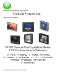
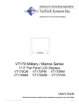
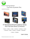
Solutions for Demanding Applications
VarTech Systems Inc.
Industrial CRT and Flat Panel Displays
VT170 Series
17.0” Flat Panel Series LCD Monitors
VT170W · VT170 WX · VT170P ·
VT170PSS · VT170R · VT170RX
User’s Guide
Read these instructions completely before attempting to operate your new Color Display.
Table Of Contents
Section 1
Section 5
Introduction
Touch screen
5.0
About LCD Monitors
1.0
Touch Screen Introduction
5.1
Product Safety Precautions
1.1
Touch Screen Definition
5.2
Touch Screen Serial Interface
5.3
Section 2
Display Setup
2.0
Setting up the Touch Interface
5.4
Display Features
2.1
Installing Windows NT 4.0 Touch Drivers
5.5
Unpacking The Display
2.2
Installing Windows 95/98 Touch Drivers
5.6
2.2.1 Installing Windows 2000 Touch Drivers
5.7
Included Parts
Connecting Your Display
2.3
Section 6
Signal Connections
2.4
Frequently Asked Questions
Section 3
Section 7
Getting Started
3.0
Troubleshooting Tips
Adjusting the Display
3.1
Section 8
Adjustment
3.1.1 Cleaning & Maintenance
Color Adjustment
3.1.2 Section 9
Setup Adjustment
3.1.3 Display Specifications
Section 4
Mounting Instructions
4.0
Chassis Mount Procedure
4.1
Chassis Mount Drawing
4.1.1
Panel Mount Procedure
4.2
Panel Mount Drawing
Rack Mount Procedure
Rack Mount Drawing
6.0
4.2.1
4.3
4.3.1
7.0
8.0
9.0
Section
1
Introduction
About LCD Monitors
1.0 What you gain by using an LCD monitor in your industrial controls
LCDs
are the future of display technology. CRTs although they have dropped
in cost significantly, do not offer the performance, reliability, and
mounting options available with LCDs. LCD monitors consist
primarily of an LCD, Video Board and a Back Light video. The LCD
determines to a large extent the viewing angle, brightness and contrast. Beyond that it is the function of
the video board which converts the analog RGB (Red, Green, Blue) signals from a standard video card
to a high quality, digital RGB that the LCD can display.
Recently the video card has taken on a new role. It is the responsibility of this device to “scale” a
particular video resolution to the “native” resolution of the LCD. Simply, consider that a computer is
putting out a VGA [640x480] resolution signal, yet the LCD that is connected is an XGA [1024x768]
display. The displayed picture would be in the center 1/3 of the LCD. With the introduction of the
scaling engine. The converter will mathematically recalculate the 640x480 to 1024x768. This may sound
simple but it is in fact a complex algorithm that adjusts for different aspect ratios and pixel alignment,
essentially smoothing text and graphics to produce a picture that is pleasant to the eye.
All Vartech displays from 12.1” (800x600) to 23.1 (1600x1200) incorporate scaling engines in the
converter card.
1
1.1
Product Safety Precautions
⇒
Ensure that sufficient space is available around the display to provide the circulation necessary for cooling.
⇒
Ensure that the ambient air temperature will not exceed the specified maximum
temperature.
⇒
Do not attempt to service this display yourself. The rear chassis has a seal so that
non qualified personal will not expose themselves to dangerous voltages or other
risks.
⇒
To protect from electrical shock, unplug the display power supply from the wall
before moving.
⇒
Do not expose the display to direct sunlight or heat.
⇒
Do not use this display near water
⇒
Do not place any heavy objects on the power cords. Damage may cause electrical
shock.
⇒
Unplug the power supply from the wall or unit if one of the following conditions
exists.
⇒ Power cord or plug is damaged or frayed
⇒ Liquid is spilled into the display or the display is exposed to rain or
water.
⇒ The display does not operate normally when the operating instructions are followed.
⇒ The display has been dropped or the enclosure has been damaged.
⇒ The display exhibits a distinct change in performance, indicating a
need for service.
2
Display Setup
Section
2
2.1
VT170 Series Display Features
⇒ Capable of displaying unlimited colors in a continuous spectrum. The high contrast LCD enhances
the image with no geometric distortion.
⇒ The VT170 Series directly accepts an analog 5 wire RGB with separate H/V sync or 4 wire RGB
with separate combined sync. (3 wire SOG is available as optional)
⇒ The VT170 Series is auto synchronous adjusting the display to the appropriate input between VGA,
SVGA,XGA, and SXGA.
⇒ The VT170 Series is available in Panel Mount, Rack Mount, Wall Mount or Chassis Mount industrial
packages..
⇒ The VT170 Series is supplied with a Anti-Reflective Screen unless equipped with an optional Touch
System.
⇒ The VT170 Series has an integrated 115/220VAC supply as standard on all models except the
chassis model. The chassis model has a +12V jack. The 115/220VAC supply is optional.
⇒ The V7170RX Extreme Series has V-Bonded Glass.
⇒ The V7170RX Extreme Series has Conformal Coating on all circuit boards.
⇒ The V7170RX Extreme Series has ruggedized Amphenol Connectors.
⇒ The V7170RX Extreme Series has a Thermostat controlled heater installed.
3
2.2
Unpacking and setting up your display
Your LCD monitor package will consist of the components listed below. Open shipping container
and lay all components on a flat clean surface.
2.2.1
What is included with your display
⇒
⇒
⇒
⇒
⇒
⇒
⇒
2.3
VT170R or VT170P, or VT170C or VT170W LCD Monitor
5 ft Video Cable
Chassis model only has a +12V power connection. (115/220VAC Power Supply is optional)
10-32 Mounting Hardware. (For use with Panel Mount only)
6 ft RS232 Touch Interface Cable (Optional when touch is installed)
CD ROM with Touch Screen Drivers (Optional when touch is installed)
Users Manual
Connecting the Display
1. Connect all cables to the computer first. This would include the VGA cable and the optional
RS 232 serial touch screen connection.
2. After connecting the cables between the LCD monitor and the computer, plug the customer
supplied +12VDC source to the 12V connection on the rear (Chassis model only) . All other
models have a integrated 115/220VAC power supply.
3. Once the +12V or the 115/220VAC connection is made, the display is active.
4. If your computer was off, turn on your computer.
5. Your display should now operate as a normal computer display showing your windows or
whatever video is being sent to the flat panel.
Note: If for any reason the display goes blank and gives an “out of Range” or “No Input Signal”,
your computer or video source is putting out a signal that is out of range of the LCD’s video
board. If this happens, reboot the computer or video source and make sure you are inputting the
correct signal. If the display doesn’t work properly, it may be because:
(a) The resolution is to high or low for the LCD.
(b) The refresh rate is set to high. Refresh on an LCD is different than a CRT. Set the refresh to
60Hz. CRT’s need a high refresh rate to avoid flicker. The refresh rate has no impact on
LCD’s.
(c) The power source is incorrect.
(d)The unit is malfunctioning. If you believe this to be true, disconnect the video cable from the
rear of the LCD and connect to a known good computer CRT display. If the computer display is
working satisfactory and the video is within the appropriate range, then contact Vartech
Customer service for a RMA number.
2.4
Signal Connections
To avoid irregular operation and /or damage to the display, please insure correct video is being
supplied as shown on the following page.
4
2.4
Signal Connections Cont.
You can use an HD-15 connector cable or a BNC adapter cable to connect the flat panel monitor
to the host computer. The HD-15 video cable (supplied in the kit) you use with this monitor is
equipped with a conventional HD-15 connector at each end.
Note: The following figure is the view looking into the pin end of the male connector or solder
term end of the female connector.
HD-15 Video Connector
The following table provides the pin numbers and corresponding pin
assignments for the HD-15 video connector.
Pin assignments for the HD15 video connector.
Pin 1
Red Video
Pin 2
Green Video
Pin 3
Blue Video
Pin 4
Not Used
Pin 5
Return
Pin 6
Red Video Ground
Pin 7
Green Video Ground
Pin 8
Blue Video Ground
Pin 9
Pin 10
Pin 11
Pin 12
Pin 13
Pin 14
Pin 15
Standard Resolutions Supported
⇒
640 x 480 (VGA)
⇒
800 x 600 (SVGA)
⇒
1024 x 768 (XGA)
⇒
1280 x 1024 (SXGA)
Pin assignment for 9 Pin Optional Touch Screen Connector.
Pin 1
DCD
Data Carrier Detect
Pin 2
RD (Rx)
Receive Data
Pin 3
SD (Tx)
Transmit Data
Pin 4
DTR
Data Terminal Ready
Pin 5
SB
Signal Ground
Pin 6
DSR
Data Set Ready
Pin 7
RTS
Request to Send
Pin 8
CTS
Clear to Send
Pin 9
NC
No Connection
5
No Connection
Sync Ground
Not Used
Bi-Directional Data
Horizontal Sync
Vertical Sync
Data Clock (SCL)
2.4
Signal Connections Cont.
Optional BNC Adaptor Cable
A 5-BNC-to-HD-15 adapter cable is available. The functions of the cables are described below.
⇒ R, B, and G: Red, Green, and Blue input connectors to establish color.
These are used for RS-343 analog signals.
⇒ HS/CS: Separate horizontal/composite sync signal from the video
source.
⇒ VS: Separate vertical sync signal from the video source.
BNC Adapter Cable
This table describes the signal types you can use with the connectors:
BNC Signal Types
BNC Signal Type
Description
Sync-on-Green
(optional)
Use the three video connectors.
Horizontal and vertical syncs are
supplied on the green video line.
Composite Sync
Use the three video connectors plus the
horizontal sync/composite sync input.
Separate Horizontal
and Vertical Sync.
Use the three video connectors plus the
horizontal sync/composite sync and
vertical sync input.
6
R G B HS/ VS
CS
X X X
X X X X
X X X X
X
Section
3
Getting Started
3.1
Adjusting the display
The VT170 Series display has an embedded microprocessor in the converter card. Once you
have the unit displaying the resolution you desire for your application do the following:
In order to navigate to the appropriate adjustments, press Menu and the OSD layout chart will
appear as indicated as shown below.
Vartech Displays, Inc
Menu
Select
Down
Up
Source
Definition of OSD (on screen display) Adjustments
There are seven membrane buttons (as shown above) located on the rear of the unit. They will
activate the OSD and allow navigation to all adjustments if your unit requires adjustment.
Press MENU and a major adjustment category will appear. Press DOWN or UP and you will
see the remaining adjustment categories. The actual adjustment categories are listed under each
major category (bold) as shown below.
ADJUSTMENT
Brightness, Contrast, Clock, Phase, H Position, V Position, Auto
COLOR ADJUSTMENT
User, 6500, 9300
SETUP
Language, Image Size, OSD H Position, OSD V Position, Transparency, Zoom
PIP (Not available on this model)
On/Off, PIP Source, PIP Size, PIP H Position, PIP V Position, PIP Image
AUDIO (Not available on this model)
Volume, Bass, Treble, Mute, Sound
7
3.1.1
Adjustment
NOTE: The following adjustments are all under the ADJUSTMENT category. The outlined
procedure covers the sequential adjustments under this category. If you desire to move to another category, press MENU and the UP or DOWN button and proceed to the desired
category.
All adjustments are graphically illustrated in yellow along with a digital value.
Brightness
Press MENU. Press the UP or DOWN button until you reach the ADJUSTMENT
Category. Next press the SELECT button. Press the UP or DOWN button until you reach
BRIGHTNESS. Now press the UP/DOWN arrow to obtain the desired brightness level.
When complete press UP/DOWN button and you can select the next desired adjustment.
Contrast
Press MENU. Press the UP or DOWN button until you reach the ADJUSTMENT
Category. Next press the SELECT button. Press the UP or DOWN button until you reach
CONTRAST. Now press the UP/DOWN arrow to obtain the desired contrast level.
When complete press UP/DOWN button and you can select the next desired adjustment.
Clock
Press MENU. Press the UP or DOWN button until you reach the ADJUSTMENT
Category. Next press the SELECT button. Press the UP or DOWN button until you reach
CLOCK. Now press the UP/DOWN arrow until the screen image is sharp and there is no
screen “jitter”. When complete press UP/DOWN button and you can select the next desired
adjustment.
Phase
Press MENU. Press the UP or DOWN button until you reach the ADJUSTMENT
Category. Next press the SELECT button. Press the UP or DOWN button until you reach
PHASE. Now press the UP/DOWN arrow until the screen image is sharp and there is no
screen “jitter”. NOTE: You may desire to readjust Clock and Phase alternately
When complete press UP/DOWN button and you can select the next desired adjustment.
H Position
Press MENU. Press the UP or DOWN button until you reach the ADJUSTMENT
Category. Next press the SELECT button. Press the UP or DOWN button until you reach
H Position. Now press the UP/DOWN arrow until the screen is centered in the horizontal
direction. When complete press UP/DOWN button and you can select the next desired
adjustment.
V Position
Press MENU. Press the UP or DOWN button until you reach the ADJUSTMENT
Category. Next press the SELECT button. Press the UP or DOWN button until you reach
V Position. Now press the UP/DOWN arrow until the screen is centered in the vertical
position. When complete press UP/DOWN button and you can select the next desired
adjustment.
8
3.1.2
Color Adjustments
NOTE: The following adjustments are all under the ADJUSTMENT category. The outlined
procedure covers the sequential adjustments under this category. If you desire to move to another category, press MENU and the UP or DOWN button and proceed to the desired
category.
All adjustments are graphically illustrated in yellow along with a digital value.
RED
Press MENU. Press the UP or DOWN button until you reach the COLOR
ADJUSTMENT category. Next press the SELECT button. Press the UP or DOWN arrow
until you reach USER. This will display the RED, GREEN and BLUE controls.
Press SELECT and RED adjustment will appear. Press the UP or DOWN arrow to adjust
RED to the desired level. When complete press UP/DOWN button and you can select the
GREEN adjustment.
GREEN
Press the UP or DOWN button until you reach GREEN. .
Press the UP or DOWN arrow to obtain the desired level of green. When complete press
UP/DOWN button and you can select the BLUE adjustment.
BLUE
Press the UP or DOWN button until you reach BLUE. .
Press the UP or DOWN arrow to obtain the desired level of blue. When complete press UP/
DOWN button if you desire to readjust any colors again.
COLOR TEMPERATURE (6500K)
If you desire a fixed color temperature of 6500K proceed as follows.
Press MENU. Press the UP or DOWN button until you reach the COLOR
ADJUSTMENT category. Next press the SELECT button. Press the UP or DOWN arrow
until you reach 6500K. This will display in yellow. Press SELECT if you desire the colors to
emulate 6500K. Press MENU to return to another adjustment.
COLOR TEMPERATURE (9300K)
If you desire a fixed color temperature of 9300K proceed as follows.
Press MENU. Press the UP or DOWN button until you reach the COLOR
ADJUSTMENT category. Next press the SELECT button. Press the UP or DOWN arrow
until you reach 9300K. This will display in yellow. Press SELECT if you desire the colors to
emulate 9300K. Press MENU to return to another adjustment
9
3.1.3
Setup Adjustments
NOTE: The following adjustments are all under the ADJUSTMENT category. The outlined
procedure covers the sequential adjustments under this category. If you desire to move to another category, press MENU and the UP or DOWN button and proceed to the desired
category.
All adjustments are graphically illustrated in yellow along with a digital value
LANGUAGE
Press MENU. Press the UP or DOWN button until you reach the SETUP
ADJUSTMENT category. Next press the SELECT button. Press the UP or DOWN
button until you reach LANGUAGE. Press the UP or DOWN arrow to select ENGLISH,
ITALIANO, ESPANOL or DEUTSCH.
IMAGE SIZE
Press MENU. Press the UP or DOWN button until you reach the SETUP
ADJUSTMENT category. Next press the SELECT button. Press the UP or DOWN
button until you reach IMAGE SIZE. Press SELECT for full picture size.
OSD H POSITION
Press MENU. Press the UP or DOWN button until you reach the SETUP
ADJUSTMENT category. Next press the SELECT button. Press the UP or DOWN
button until you reach OSD H POSITION. Press SELECT . Press the UP or DOWN
arrow to adjust the horizontal position of the OSD window. Press the UP or DOWN button
to OSD V POSITION.
OSD V POSITION
Press MENU. Press the UP or DOWN button until you reach the SETUP
ADJUSTMENT category. Next press the SELECT button. Press the UP or DOWN
button until you reach OSD V POSITION. Press SELECT . Press the UP or DOWN
arrow to adjust the vertical position of the OSD window. Press the UP or DOWN button to
proceed to the next adjustment.
TRANSPARENCY
Press MENU. Press the UP or DOWN button until you reach the SETUP
ADJUSTMENT category. Next press the SELECT button. Press the UP or DOWN
button until you reach TRANSPARENCY. Press SELECT . Press the UP or DOWN
arrow to adjust the transparency to the desired level . Press the UP or DOWN button to
proceed to the next adjustment.
ZOOM
Press MENU. Press the UP or DOWN button until you reach the SETUP
ADJUSTMENT category. Next press the SELECT button. Press the UP or DOWN
button until you reach ZOOM. Press SELECT . Press the UP or DOWN
arrow to adjust zoom as desired. NOTE: The H and V zoom positions are fixed.
10
Mounting Instructions
4
4.1
Chassis Mount Procedure
Mounting instructions for chassis mount
The chassis mount contains a simple frame with mounting holes. Traditionally captive hardware would be used to secure the display against a panel with the proper hole size based on
the mechanical drawing. The chassis display is supplied with a piece of Plexiglas material
sealed to the front for protection. If the display is equipped with a touch screen, the touch
screen takes the place of the Plexiglas for protection of the LCD.
The unit is normally supplied for +12V operation, however it is available with a 115/220VAC
supply.
11
4.1.1
Chassis Mounting Drawing
THIS OPTION NOT AVAILABLE
12
4.2
Panel Mount Procedure
Panel Mounting Procedure
1. Cut and drill the panel (refer to panel mount drawing). Measurements are in inches.
Panel Mounting Cutout
2. If access to the side of the monitor is not available following installation, attach the power
and video cables to the side of the monitor at this time.
3. Install the monitor in the prepared cutout.
4. Install the lock nuts and washers, supplied with the monitor, behind the holes running along
the sides and top/bottom of the cutout in the panel. Extra lock nuts and washers are provided.
Note: Use #10-32 nuts for mounting.
5. Tighten all mounting nuts evenly to a torque of 24 inch-pounds.
ATTENTION: Mounting nuts must be tightened to a torque of 24 inch-pounds to provide
panel seal and avoid potential damage. Vartech Displays assumes no responsibility for water or
chemical damage to the monitor or other equipment within the enclosure due to
improper installation.
6. Attach the power and video cables to the side of the monitor if you
have not already done so. .
13
4.2.1
Panel Mount Dimensions and Mounting Drawing
14
4.3
Rack Mount Procedure
Rack Mounting Procedure
1. Carefully remove the monitor from its packaging.
2. Locate holes in the cabinet front mounting rails corresponding to the holes in the monitor
front panel. Install clip nuts behind the holes in the rails if threaded rails are not provided.
Note: The mounting rails that run vertically along the inside edges of the front opening of an
EIA rack cabinet can be of two types:
· “Wide” rails have holes spaced 0.5"(12.7 mm) and 1.25"(31.8 mm) on centers, in a repeating
pattern. Wide rails are prevalent in Europe. · “Universal” rails have holes spaced 0.5"(12.7 mm),
0.625"(31.8 mm), and 0.625"(31.8 mm) on centers, in a repeating pattern. Thus, the universal
rails have a hole pattern that contains the wide pattern but provides an additional hole at the
midpoint of the pattern. Universal rails are most prevalent in the US.
3. Install the monitor into the cabinet from the front.
4. Secure the monitor chassis to the cabinet by installing panel mounting screws through the
holes in the monitor front panel and into the rails behind.
15
4.3.1
Rack Mount Dimensions and Mounting Drawing
16
Section
5
5.1
Touch Screen
Touch Screen Introduction
Touch screen interfaces have become the standard interface in the past 5 years. They are, rugged,
reliable, extremely flexible and easier than ever to implement! Over 90% of the display packages
Vartech Systems builds are touch screen systems. If you are uncertain about using a touch screen,
or are having difficulty, please call us. The universal acceptance of the Windows GUI [Graphical
User Interface] along with the extensive use of a mouse interface has significantly accelerated the
use of touch interface. Basically think of your touch screen as if it were a mouse.
5.2
Touch Screen Definition
Quite simply, Vartech Systems touch systems are a mouse emulator. By installing a software driver
and connecting to a serial port, the touch screen will support all the primary mouse functions:
Our standard touch screen interface, is a high resolution analog resistive. Following is a quick
explanation of what all this means.
High Resolution: The touch screen resolution is 400 ppi [points per inch]
Analog Resistive: The actual touch glass is an analog device. Meaning there is a very low voltage
applied to the X and Y axis of the touch screen. This current is applied to ITO [Iridium Tin Oxide]
that is sputtered onto a polyester membrane. When you touch the screen you are changing the
resistance on both the X and Y axis, producing an analog value that references a particular location.
This type of screen can be activated with a gloved finger or mechanical stylus.
The touch screen itself is connected to electronics that provide the Analog to Digital conversion.
When the screen is touched, the electronics convert the analog voltage to a digital value and add a
“Mouse Click”, then sends the data to the serial port that the driver is loaded to. When the touch is
released the new XY location is sent along with a “Mouse Up Click”.
This system requires no special software knowledge, and can be installed and set up in minutes.
The following section gives a detailed explanation of the software setup and configuration.
Since the touch screen interface is RS-232, the recommend maximum distance from the PC is 50
feet. In reality, every application is different. The touch driver default baud rate is 9600, and we
have tested the driver and interface with good quality cables to 50 feet.
With RS-232 line drivers this can be extended almost indefinitely.
17
5.2
Touch Screen Definition Cont.
Connecting the touch screen
1. Make sure all optional cables have been received.
2. Connect one end of the 6 foot touch screen serial cable to the touch screen port D9 connector on the side of the monitor.
3. Connect the other end to any communications port on the host computer.
4. Tighten the captive screws on the cable connector to secure it.
5.3
Touch Screen Serial Interface
All touch controllers are configured by default to provide serial communications at 9600 baud, 8 data
bits, 1 stop bit, no parity. For Vartech flat panels equipped with touch screens, a serial
communications cable is required. This 6 foot cable comes with the unit in the accessory kit.
The cable is a straight wired serial (RS-232) cable with a male DE-9 D-shell connector on the
monitor end. The cable provides a communications channel between the touch screen
controller, which is mounted inside the monitor, and an RS-232 serial port on the host computer.
Because the touch controller obtains power from the monitor's power supply, no external touch power
connections are necessary.
Software supplied with the touch screen must be loaded on the host computer to handle
communications with the touch controller over the channel.
Because the touch screen emulates a mouse, there may be compatibility issues involving how the touch
screen emulates mouse buttons, especially multiple buttons.
5.4
Setting up the Touch Screen Interface
Enabling the Touch Screen Interface
The Flat Panel Monitor provides a female DE-9 connector for the touch interface. This connector provides the serial interface for the touch controller.
Interconnecting wiring to the host serial port connection is shown in the
following table.
Touch screen Interface
Monitor
(DCE Device)
DE-9 (Female)
1
2
3
4
5
6
7
8
9
Host (DTE Device)
DE-9 (Male)
DB-25 (Male)
1
8
2
3
3
2
4
20
5
7
6
6
7
4
8
5
9
22
Signal Description
Not Connected (DCD)
Transmit Data (TXD)
Receive Data (RXD)
Data Terminal Ready (DTR)
Common Signal Return (SG)
Not Connected (DSR)
Request To Send (RTS)
Clear To Send (CTS)
Not Connected
18
5.5
Installing Touch Screen Driver Windows NT 4.0
1. Start your computer.
2. Insert the MonitorMouse for Windows NT disk into drive A.
3. Click the Start button then click Run.
4. Type “a:\setup” in the space provided and press Enter.
5. Follow the directions on the screen.
6. MonitorMouse for Windows NT provides two Installation options. Most users
should select Typical (the default) and click Next to continue. Custom allows
you to install the sample touch screen programming files.
7. The Touch screen Setup dialog box will appear. Specify the type of
touch screen controller you are using and how it is connected. Also specify the
language you want to use in the Touch screen Control Panel. Click OK to
confirm that the Setup is correct.
8. Complete the Setup program.
9. Shutdown and restart Windows NT. Continue the steps on the next page.
10. Click the Start button, then click Settings, then click Control Panel.
11. Double-click Elo Touch screen to run the Touch screen Control Panel.
12. Click the Calibrate button and touch each of the three targets as they appear
on the screen. Touch Yes when the cursor lines up correctly with your finger.
Touch OK to close the Touch screen Control Panel.
Note:
If at any time the screen cursor is not directly under your finger on a touch, the touch screen
can be re calibrated at anytime by going to the Windows control panel and selecting the Elo
Icon and selecting Calibrate.
5.6
Installing Touch Screen Driver Windows 95/98
Start your computer.
2. Insert the MonitorMouse for Windows 95 disk into drive A.
3. Click the Start button then click Run.
4. Type “a:\setup” in the space provided and press Enter.
5. Follow the directions on the screen.
6. MonitorMouse for Windows 95 provides two installation options. Most users should select
Typical:
(the default) and click Next to continue.
Custom: allows you to install the sample touch screen programming files.
7. The Touch screen Setup dialog box will appear. Specify the type of touch screen controller
you are using (Serial SmartSet Model 2210) and how it is connected.
Click OK to confirm that the Setup is correct.
8. Complete the Setup program.
9. Restart Windows 95.
10. Click the Start button, then click Settings, then click Control Panel.
19
5.6
Installing Touch Screen Driver Windows 95/98
11. Double-click Elo Touch screen to run the touch screen control panel.
12. Click the Calibrate button and touch each of the three targets as they appear on the screen.
13. Click yes when the cursor lines up correctly with your finger. Click OK to close the touch
screen control panel.
Note:
If at any time the screen cursor is not directly under your finger on a touch, the touch screen
can be calibrated at anytime by going to the Windows control panel and selecting the Elo Icon
and select Calibrate.
5.7
Installing Touch Screen Driver Windows 2000
1. Start your computer.
2. Insert the MonitorMouse for Windows 2000 disk into drive A.
3. Click the Start button then click Run.
4. Type “a:\setup” in the space provided and press Enter.
5. Follow the directions on the screen.
6. MonitorMouse for Windows 2000 provides two Installation options. Most users
should select
Typical (the default) and click Next to continue.
Custom allows you to install the sample touch screen programming files.
7. The Touch screen Setup dialog box will appear. Specify the type of
touch screen controller you are using and how it is connected. Also specify the
language you want to use in the Touch screen Control Panel. Click OK to
confirm that the Setup is correct.
8. Complete the Setup program.
9. Shutdown and restart Windows 2000. Continue the steps on the next page.
10. Click the Start button, then click Settings, then click Control Panel.
11. Double-click Elo Touch screen to run the Touch screen Control Panel.
12. Click the Calibrate button and touch each of the three targets as they appear
on the screen. Touch Yes when the cursor lines up correctly with your finger.
Touch OK to close the Touch screen Control Panel.
Note:
If at any time the screen cursor is not directly under your finger on a touch, the touch screen
can be re-calibrated at anytime by going to the Windows control panel and selecting the Elo
Icon and selecting Calibrate.
Note: For latest touch information, refer to www.elotouch.com
20
Section
6
Frequently Asked Questions
6.0 Why should I use and Analog interface LCD monitor?
There are several reasons to use an analog interface display, but there are 3 primary reasons
1 Analog RGB [Red Green Blue] video interface has been
bee around
aroundfor
forabout
about1010years
yearsand
andhas
has
proven to be a robust, flexible, cost effective video interface that has expanded from VGA [640 x
x 480]totoUXGA
UXGA[1600x1200]
[1600x1200]resolution.
resolution.
480]
2 It is easily supported by 100’s
of
and and
videovideo
cardcard
manufacturers
hundredscomputer
of computer
manufacturers.
3 It is the defacto video interface [see note below]
below].
Note: There are several companies all competing for the New Digital Standard for video data
displays. Although we are exploring several competing standards we believe that the DVI standard is
is
going
next
defacto
video
standard.
When
have
proven
that
compatible
component
going
to to
bebe
thethe
next
defacto
video
standard.
When
wewe
have
proven
that
compatible
component
parts, cables and panels are reasonably available we will have a complete digital panel offering.
Are LCD’s rugged and reliable?
We can only talk from our experience, but after shipping thousands of units of all sizes, LCDs
have proven to be far more reliable then their CRT predecessors.
Aren’t LCD s very expensive?
Although an equivalent LCD solution is more expensive a CRT solution we believe that an LCD is
a better solution for industrial applications, and LCDs have dropped significantly in price over the
past 2 years. Further we expect a continued price reduction.
You also need to consider the total cost of ownership of an LCD. They have a longer life
expectancy then a CRT. Also, if you are considering a touch screen, LCD touch screens are lower
in cost (both new and as replacement parts) then the compound curved CRT touch screens.
Aren’t LCDs difficult to setup?
Using an analog RGB interface you can use the same computers and video cables you are currently
using on your CRT monitor application. Vartech’s LCDs are Plug and Play to your current and
future video display sub system.
21
7.0
Section 7
Trouble
Troubleshooting Tips
Troubleshooting Tip
No Picture
⇒ The signal cable should be properly connected to the
display card and computer.
⇒ Try disconnecting the video cable from the display and
connecting to a CRT display if available to confirm the
presence of proper video.
⇒ Make sure power is connected to the proper DC or AC
source.
⇒ Make sure the resolution mode is supported by the display
Image Persistence
Image persistence occurs when a ghost of an image remains
on the screen after the monitor has been turned off. Unlike a
CRT monitor, an LCD monitor’s image persistence is not
permanent. To erase an image ghost, turn the monitor off for
as long as the image was displayed. If the image was on for
one hour and the ghost of the image remains, the display
should be turned off for one hour to erase the image. To
avoid this problem, use a screen saver.
Picture Quality & Image Stability ⇒ Check for proper video cable for proper grounding and
shielding.
⇒ Check the signal source for proper signal.
⇒ Check for proper adjustment of the Phase and Frequency
controls.
⇒ Check for proper recommended signal timing.
Green LED not lit
Check for proper power and power connections
Green LED blinking
This indicates absence of video or proper video for this display
Display image is not properly
sized
⇒ Adjust the Vertical and Horizontal size controls via the
OSD. (Reference setup adjustments)
⇒ Ensure that a supported mode is selected on the display
card or system being used. Consult the display card or
system manual for proper video.
No S-Video or NTSC operation ⇒ Check for proper connections.
⇒ Check the setup instructions for proper input selection.
If these tips do not solve your problem, contact Vartech Systems Customer Service support.
22
7.0
Troubleshooting Tips Cont.
Trouble
Screen is blank.
Troubleshooting Tip
Screen saver activated.
Video Cable problem. Check for proper installation
Change video cable
Faulty video display. Needs Service
Image is dim, even with
brightness and contrast
controls set full UP.
Video cable problem. Check for proper installation of cables
Faulty video source
Faulty display
Image not centered
Reset the horizontal and vertical positioning using the on-screen
menu. Check to see if video source is operating within the
monitor’s range.
Image will not adjust
Video timing outside of range. Use the on-screen menu to ad
just the Clock Setting. Make sure timing is within VESA
standard.
.Image is not stable.
Monitor has incorrect or bad sync signals..
Check for proper video cable installation.
Replace suspected faulty cable.
Check to ensure that video source is
operating within the display’s range.
Vertical shaded bars on
Screen image
Horizontal size not properly adjusted. Adjust horizontal size
settings.
Colors are missing
Faulty video cable.
Missing from video source. Connect video source to another
display.
Screen jitter or noisy display
Monitor clock phase not properly adjusted.
Video cable problem.
External noise interference.
Slight distortion in text or
Graphics.
Not working in native resolution.
Display is present but “bars” Ground loop problem between computer and display
Appear or roll across screen Interference from adjacent equipment.
The background looks
Acceptable but text and
Icons seem to be missing
rows of pixels
Video running interlace mode.
23
8.0
Cleaning and Maintenance
Cleaning
Occasionally clean the display panel and cabinet with a soft cloth dampened (not soaked) with a
mild (non-abrasive) glass cleaner. Keep turning a fresh side of the cloth toward the screen
surface to avoid scratching it with accumulated grit.
Note: The solvent should be applied only to the cloth, and not directly on the monitor screen.
Do not use paper products as they may scratch the surface. To minimize the risk of abrasion,
allow the screen to stand dry.
Special care should be taken when cleaning a touch screen or polycarbonate shield that is
installed over the screen. Abrasive and certain chemical cleaners can easily damage the surface.
Note: For best results cleaning a monitor with the optional antireflective tempered glass display
shield, a solution of denatured alcohol is recommended to thoroughly clean the display.
Never use alcoholic or ammoniac cleaners to clean the polycarbonate shield or a touch screen.
Replacing a Line Cord
To avoid shock and fire hazards, the monitor’s power cord should be replaced if the insulation
becomes broken or if it develops a loose internal connection.
Other Maintenance
Qualified service personnel should perform all maintenance, except for
the power cord replacement described above.
24
9.0
VT170 Series Specifications
Display Size
17.0 Inch
Panel Type
TFT Active
Resolution Capabilities
VGA to SXGA*
Pixel Format
640 x 480, 800 x 600,
1024 x 768, 1280 x 1024*
Pixel Pitch
.264mm (w) x .264mm (h)
Viewing Angle
Left / Right: 89º/89º
Up / Down: 89º/89º
Active Display Area
13.304” (w) x 10.643” (h)
337.920mm (w) x270.336mm (h)
Contrast Ratio
600:1 Typical
Brightness
250 Nits
Backlight
50,000 Hours Typical
Colors Supported
16.8M
Video Input
0.7Vp-p / 75 ohm, Digital
Sync
TTL Separate H&V
Combined, SOG
Video Input Connector
HD15(F), DVI-D, RCA (NTSC/PAL),
5 Pin Mini Din (S-Video)
Optional:
HD15(M) to 5xBNC(F) Interface Cable
Power Source
90-264VAC Universal
Optional:
12VDC @ 2.5A
Power Consumption
35 Watts @ 115VAC
4 Watts Sleep Mode
Temperature
Operating: 0 to 50º C
Storage: -20 to 60º C
Optional:
Operating: -20ºC or -40ºC
Altitude
Operating: up to 10,000 ft
Storage: up to 40,000 ft
25
VARTECH SYSTEMS INC.
HEADQUARTERS
11529 Sun Belt Ct.
Baton Rouge, Louisiana 70809
Toll-Free: 800.223.8050
International Phone: 001.225.298.0300
Fax: 225.297.2440
E-mail: [email protected]
www.vartechsystems.com
150-022-002
9.25.02