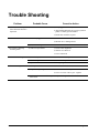
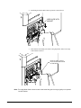
1
Users Manual
Model SNAP 700 Downstacker
Option
AVERY DENNISON
Manual Edition 1.0
04 Dec. 2012
Manual Part Number 628098
WARNING
This device complies with Part 15 of the FCC Rules. Operation is subject to the following two conditions:
1) this device may not cause harmful interference, and
2) this device must accept any interference that may cause undesired operations.
This Class A digital apparatus meets all requirements of the Canadian Interference
Causing Equipment Regulations. Cet appareil numerique de la classe A respecte toutes les exigences du
Reglement sur le material broilleur du Canada
Users Manual Model 500 Downstacker
Contents
Scope
4
Introduction................................................................................................................................ 4
Warranty Information
5
Warranty Policy ......................................................................................................................... 5
Description / Specifications
7
Stacker Description.................................................................................................................... 7
Optional Stacker Specification................................................................................................... 8
Customer Responsibility
9
Location of Stacker .................................................................................................................... 9
AC Power Line ........................................................................................................................ 10
Unpacking / Installation
10
Unpacking................................................................................................................................ 10
Inventory of Components......................................................................................................... 11
Down Stacker Option
12
Installation ............................................................................................................................... 12
Adjustments ............................................................................................................................. 13
Operation ................................................................................................................................. 14
Trouble Shooting
15
Installation Instructions for Stacker Option 580028
16
Installation Procedure .............................................................................................................. 16
Mechanical Assembly Drawings
19
Stacker Assembly Drawing...................................................................................................... 20
Stacker Parts List ..................................................................................................................... 23
Label Stop Assembly Drawing ................................................................................................ 24
Label Stop Parts List................................................................................................................ 25
Users Manual Model 500 Downstacker
Scope • 3
Scope
Introduction
This user manual was arranged for the person who is going to operate the machine.
The information is arranged in the order that is needed to install and operate the
machine. It starts with general information, then to unpacking, installing, stacker
operation and finally care and maintenance of the stacker.
We at AVERY DENNISON hope that you will come to appreciate the efforts and
quality that have gone into producing your AVERY DENNISON 500 Stacker and
wish to remind you that you are our number one priority. We welcome any
constructive comments or criticisms so that we may continue to offer you the best
products in the industry for years to come.
4 • Scope
Users Manual Model 500 Downstacker
Warranty Information
Warranty Policy
Avery Dennison Retail Information Systems, In-Plant Printing Solutions provides the following warranty policy.
Scope
Warranties against defects from workmanship for equipment and parts manufactured and sold from
Miamisburg, OH. Includes time and material except as otherwise noted below.
Time
−
−
−
New equipment and parts: 6 months
Refurbished equipment and parts: 90 days
Warranty period starts when equipment ships from selling location.
General Conditions
Avery Dennison extends warranty coverage under the following conditions.
−
Equipment and parts will perform within published specifications. Promised or implied statements by any
Avery Dennison employee or representative will not be deemed to vary the terms of the warranty.
−
Equipment and parts must be installed and operated according to recommended procedures and
operating conditions.
−
Consumable elements are not covered. Consumable elements are those that show normal wear from
typical equipment usage including, without limitation, printheads, knives, rollers in contact with the web,
and sonic units. Avery Dennison reserves the right to determine which elements are defined as
“consumable.”
−
No customer maintenance may be performed except as directed by qualified Avery Dennison personnel.
−
Equipment and parts damaged by negligence or abuse are not covered.
−
Avery Dennison US reserves the right in its sole discretion to incorporate any modifications or
improvements in the machine system and machine specifications which it considers necessary but does
not assume any obligation to make said changes in equipment previously sold.
Equipment Purchased In US and Shipped In US
−
Avery Dennison US covers warranty for equipment and parts installed and operated in the Americas
(United States, Canada, Mexico, Central America, Caribbean Region, and South America excluding
Brazil).
−
Outside the US, the local Avery Dennison office is responsible for equipment and parts warranty.
Customers must ensure coverage during machine purchase.
Users Manual Model 500 Downstacker
Warranty Information • 5
−
Equipment purchased and exported to regions outside local Avery Dennison office coverage are not
covered by warranty. The purchasing agent must acquire a service contract from the Avery Dennison
office where the equipment or parts are operated to ensure machine coverage. For example, if an agent
purchases a printer in the US, exports to Brazil, and then needs warranty coverage, Avery Dennison Brazil
has no obligation to provide warranty coverage. The agent must purchase services from Avery Dennison
Brazil.
THE WARRANTIES PROVIDED HEREIN ARE EXCLUSIVE AND ARE IN LIEU OF ANY IMPLIED
WARRANTY OF MERCHANTABILITY, FITNESS FOR A PARTICULAR PURPOSE OR OTHER WARRANTY
OF QUALITY OR PERFORMANCE, WHETHER EXPRESS OR IMPLIED. EXCEPT THE WARRANTY OF
TITLE, IN NO EVENT SHALL AVERY DENNISON BE LIABLE FOR ANY INDIRECT, INCIDENTAL OR
CONSEQUENTIAL DAMAGES, EVEN IF AVERY DENNISON HAS BEEN ADVISED OF THE POSSIBILITY
OF SUCH DAMAGES.
Service
When ordering machines and supplies in the U.S.A., reference all correspondence to the address below.
AVERY DENNISON Corporation
170 Monarch Lane
Miamisburg, OH 45342
Call:
1-800-214-0872 or (937) 865-2123
Fax:
(000) 000-0000
For spare parts, requests for service or technical support, contact
AVERY DENNISON Corporation
170 Monarch Lane
Miamisburg, OH 45342
Call:
1-800-214-0872 or (937) 865-2123
Fax:
(000) 000-0000
For parts and service in other countries, please contact your local AVERY DENNISON supplier.
6 • Warranty Information
Users Manual Model 500 Downstacker
Description / Specifications
Stacker Description
The Down Stacker Option is a low-end stacker for coated and woven fabric labels.
The stacker has several adjustments that can be made for the label size and material
to be printed and cut on the AVERY DENNISON 500 Printer or the Sonic Knife
when attached to an AVERY DENNISON 500 Printer. On most coated labels tested
to date, the finished stack is fairly even on the edges and the length may vary
dependent on stacker configuration adjustments, label material and size. The stack
for woven labels will not be quite as good as the coated tapes, but removal of the
labels and jogging them together on a table like a deck of cards is easily managed.
Figure 1 - AVERY DENNISON Model 500 Downstacker
Users Manual Model 500 Downstacker
Description / Specifications • 7
Optional Stacker Specification
Label Size
Min: 1/2" (12.7mm) web x 7/8" (22.2mm) feed
(standard stacker)
Max:
(standard stacker)
2 1/4" (57.2mm) web x 5" (127mm) feed
5:1 web feed to width ratio
(Examples - ½”web = max feed 2 ½”
3/4”web = max feed 3 3/4”)
Label Capacity
4800TWT material = Approximately 2,000 labels for full stacker
Dimensions
12" (305mm) high x 7" (178mm) wide
Including stacker x 6.0" (152mm) deep
Weight
3.6 Lbs. (1.64 Kg.)
Electrical
Interface directly to the printer
Temperature
41°F (5°C) to 104°F (40°C)
Humidity
5% to 90% non-condensing
8 • Description / Specifications
Shipping weight 6 Lbs. (2.73Kg.)
Users Manual Model 500 Downstacker
Customer Responsibility
Location of Stacker
The printer w/Stacker weighs approximately 50 Lbs (23 Kg) and requires a table of
sufficient quality and strength to handle this load while the system is operating.
AVERY DENNISON recommends an industrial type worktable having the
approximate dimensions of 72" wide to 30" deep to 32" high. Refer to Figure 2.
Figure 2 - Recommended Workstation Layout.
The location of the AVERY DENNISON 500 Printer should be based on human
factors. The Stacker should be located in an area that maintains optimum flow of
your product while providing for the operator’s comfort. AVERY DENNISON has
taken significant steps to ensure that the operator controls and operations are easily
accessible. This goal can only be met, however, if the printer is also located with
human factors in mind. These include the height of the Stacker, the space around the
Stacker and the accessibility to the printer.
While AVERY DENNISON has designed the system to be reasonably quiet, it is
recommended to locate the printer in an area where printing and cutting repetitious
noise is acceptable.
Users Manual Model 500 Downstacker
Customer Responsibility • 9
AC Power Line
The AVERY DENNISON printer requires that the electric service be 10 Amps @
115VAC or 6 Amps @ 230VAC. This will allow the computer and any additional
support or service equipment to be plugged into the same service.
The AVERY DENNISON 500 downstacker option connects directly to the printer.
The printer controls all the functions of the downstacker option.
Any electrical service that is supplying a AVERY DENNISON printer or peripheral
equipment connected to a AVERY DENNISON printer should follow standard
electrical code practices including proper grounding and neutral requirements.
The AVERY DENNISON printer was designed to operate in an industrial setting for
extended periods of time; however, the printer is controlled by a microprocessor that
is very sensitive to brownouts or power spikes. For this reason as well as the
minimum recommended current supply, AVERY DENNISON recommends that a
separate “clean” service be installed or reserved for the exclusive use of the AVERY
DENNISON printer and its peripherals.
Unpacking / Installation
Unpacking
The AVERY DENNISON 500 stacker is shipped in a cardboard carton that may be
moved by hand.
DO NOT REMOVE THE STACKER FROM THE CARTON OR UNPACK IN
THE SHIPPING / RECEIVING DEPARTMENT.
Items may be lost. Also the carton should be saved for return of the stacker if
ever required. Return shipping damage in a poorly packed carton is the
responsibility of the customer.
Open the carton from the top by cutting the taped seam on the top of the carton.
Remove the foam packing layer. (See Figure 3).
Lift the stacker from the carton by the body of the stacker. Do not lift by the
interface cable or stacker platform.
Remove the plastic over the stacker.
10 • Unpacking / Installation
Users Manual Model 500 Downstacker
Inspect the stacker for shipping damage. If obvious damage is discovered, contact
AVERY DENNISON for further instructions - in the U.S.A. at (937) 865-2123. In
countries other than the U.S.A. please contact your local AVERY DENNISON
supplier.
TOP FOAM LAYER
POLY BAG COVERING
CARTON
Figure 3 - Shipping Carton
Save the shipping materials to return to the factory for service if ever required.
Shipping containers are specially made to protect the printer. Machines returned that
are not properly packed are the responsibility of the customer for any damage.
Inventory of Components
The following list shows the additional parts (pieces) that should be included in your
AVERY DENNISON 500 Stacker shipping carton. If anything is missing, notify
AVERY DENNISON immediately - in the U.S.A. at (937) 865-2123. In countries
other than the U.S.A. please contact your local AVERY DENNISON supplier.
- AVERY DENNISON 500 Optional Downstacker
- AVERY DENNISON 500 Optional Downstacker "User's Manual"
Users Manual Model 500 Downstacker
Unpacking / Installation • 11
Down Stacker Option
Installation
Note: Turn the power off to the printer to install or remove the stacker. While no
electrical failure will occur – the software must be initialized (on power up)
to automatically recognize what option has been connected to the printer.
There are two shafts on the printer located below the Auxiliary Feed and Knife
assembly. Loosen the thumbscrew in the mount bracket of the stacker and begin to
slides the stacker on the two shafts. The top of the stacker must slide behind the Nip
Roller stripper plate. Slide the stacker in until the backside of the stacker is beyond
the size web being run.
The interface cable that extends from the bottom of the stacker assembly plugs into
the larger connector on the right side of the printer. There is a sleeve on the
connector that will snap with the connector fully engaged with the mating connector.
The two cables will only slide into each other when the connectors are properly
aligned with each other. Rotating the connector and applying light pressure inward
will engage the connectors. To remove the connector - slide the outer sleeve out and
hold it while pulling the connector out.
12 • Down Stacker Option
Users Manual Model 500 Downstacker
Adjustments
There are several adjustments that improve the quality of stacking that can be made
to the stacker. There are no incorrect settings, just adjustments that stack the label
size and material the best.
Stacker Angle
The entire stacker can be tipped from a vertical position as shown below to 20° out at
the bottom. Coated tapes tested work well with the bottom tipped out when the feed
is 2” or longer. Woven tapes work best when the stacker is vertical or almost
vertical. There is no best angle for all label lengths and materials.
Platform Adjustments
The angle of the platform can be adjusted into indefinate different locations by
loosening the thumb screw and pivoting the platform. Woven labels tested worked
better in the lower position while coated labels worked the best with the outer end
elevated. Short feeds worked best with the outer end elevated.
The label stop helps get the first few labels in the stack when it’s completely empty.
Place a cut label on the platform and slide it into the back corner. Move the label
stop to within 1/8” to the end of the label. The label stop is spring-loaded and will
slide without loosening or adjusting the mount thumbscrew.
Static Brush
The static brush has been mounted with a thumbscrew for easy adjustment to help
guide and control labels into the stacker. The brush should contact the material as it
exits the nip rollers. The static brush should be maintained in good condition for the
best stacking.
In general – a light pressure is sufficient to stack well, but long feeds will require
slightly more pressure.
Keep the static brush parallel to the nip roller mount bracket.
Users Manual Model 500 Downstacker
Down Stacker Option • 13
Operation
The platform is automatically adjusted to the sensor level hieght. The printer will
then begin to produce labels and deliver them into the stacker. As the labels begin to
build - the stacker platform will begin to descend. Once the stacker is full, a sensor
will stop the printer and light the supply LED on the control panel. Remove all the
labels from the stacker and press the Stop/Start button on the display. The platform
will return to the top and begin printing and stacking labels again.
Static Brush
Label Stop
Sensor Stacker Height
Stripper Bracket
Label Platform
Thumb Screw Adjustment
(Under label platform)
Stacker Angle
(Shown Veritcal)
14 • Down Stacker Option
Users Manual Model 500 Downstacker
Trouble Shooting
Problem
Stacker fails to move up or
down when start button is
depressed.
Probable Cause
1) Interface cable
Corrective Action
1) Not plugged in all the way.
2) Just installed and needs to be power cycled for
printer to identify option installed.
3) Printer has no batches to print.
Platform can not find home
1) Sensor unplugged
1) Remove back cover and check connections.
2) Broken wire or damaged LED
Top of stack is blocking
incoming labels
2) Sensor out of alignment
1) Outer bracket bent and needs to be reformed.
2) Sensor not operational
1) Check sensor alignment
2) Stacker not connected
3) Loose connection
Stack of labels falling over
Label not entering stacker
2) Static brush position
1) Move static brush up or down
3) Platform angle
1) Move to other position
4) Tip stacker
1) Change angle
1) Label jam in knife
1) Clean out label and debris
2) Nip roller not pulling
1) Worn rubber roller - Replace
2) Loose set screw or drive gear - Tighten
3) Soft material / narrow web hitting
static brush
Users Manual Model 500 Downstacker
1) Adjust the height of the static brush
Trouble Shooting • 15
Installation Instructions for
Stacker Option 580028
(Use with Woven Edge Fabrics less than 1 inch wide & over 4 inches long)
Option consists of:
Part No.
588048
588049
Description
Web Guide
Long Stacker Mount Shaft
Qty
1
2
Installation Procedure
1.
Remove (2) Stacker Mounting Shafts from the Sonic Knife and replace with
(2) 588049 long Stacker Mount Shafts.
BUTTON HEAD SCREWS MAY NEED
TO BE LOOSED AND THE MOUNT
ARM MAY NEED TO BE SWUNG IN
TOWARDS THE SONIC KNIFE TO
ALLOW THE STACKER TO PASS
FREELY WITHOUT INTERFERING
WITH THE OUTBOARD CONVEYOR
REMOVE STACKER MOUNTING
SHAFTS & REPLACE WITH LONG
STACKER MOUNTING SHAFTS (588049)
2.
Adjust to allow Stacker to slide freely.
3.
With Stacker installed, slide forward and tilt top back as far as possible
without blocking the Platform “Drop” Sensor.
16 • Installation Instructions for Stacker Option 580028
Users Manual Model 500 Downstacker
4.
Install Magnet backed Web Guide in position as shown below.
WEB GUIDE WITH
MAGNET
5.
Slide Stacker horizontally until Label exiting Nip Roller slides across edge
of Web Guide as shown.
EDGE OF LABEL SHOULD
GLIDE ACROSS BENT EDGE
OF WEB GUIDE
Note: The single Web Guide creates a twist in the Label that gives it enough rigidity to be pushed
into the Stacker.
Users Manual Model 500 Downstacker
Installation Instructions for Stacker Option 580028 • 17
18 • Installation Instructions for Stacker Option 580028
Users Manual Model 500 Downstacker
Mechanical Assembly Drawings
Users Manual Model 500 Downstacker
Mechanical Assembly Drawings • 19
Stacker Assembly Drawing
20 • Mechanical Assembly Drawings
Users Manual Model 500 Downstacker
Stacker Assembly Drawing
Users Manual Model 500 Downstacker
Mechanical Assembly Drawings • 21
22 • Mechanical Assembly Drawings
Users Manual Model 500 Downstacker
Stacker Parts List
ITEM
1
2
3
4
5
6
7
8
9
10
PART NO.
638005
638004
638003
588029
588028
588031
638006
638007
991640
221117
11
12
13
991510
638002
117954
14
15
16
17
18
19
117955
991419A
588001A
990327
990329
991373
20
581199A
DESCRIPTION
QTY
FRAME, STACKER 500 2/1
1
BRACKET, MIDDLE SUPPORT
1
BRACKET, STACKER MOTOR
1
BRACKET, DIODE MOUNT, FRONT
1
BRACKET, DIODE MOUNT REAR
1
COVER, LABEL SENSOR
2
SHAFT, SPROCKET
2
SHAFT, TENSIONER
1
SPROCKET, STACKER, 10T
3
STRAIN RELIEF .360 X .625"
1
BALL BEARING , 16mm O.D. x 8mm I.D.
FLG
2
SHAFT, MAIN DRIVE
1
GEAR-RIBBON 75T
1
GEAR-RIBBON 54T-15T
SPROCKET, STACKER 16T ALTERED
PLATFORM SLIDE, ALT
E-RING, 5/16
E-RING, 7/32
8 SCREW, 8-32 X 1/4 PAN PHILLIPS
HARNESS, DOWNSTACKER,
PROGRAMMED WITH GEAR
Users Manual Model 500 Downstacker
1
1
1
1
3
3
ITEM
21
22
23
24
25
26
27
28
29
30
PART NO.
588080
991182
990081
990313
989966
990005
990069
990058
989986
638010
31
32
33
990104
991455
588072
34
35
36
991508
638008
991335
DESCRIPTION
BRACKET, LABEL PLATFORM
10-32 X 3/8 SHCS w Nylon
10-32 x 1/2 SOC HD CAP SCR
THUMB KNOB, #10
#4 STAR WASHER
4-40 HEX NUT
8-32 HEX NUT
8-32 X 1/4 KNURLED CUP POINT
4-40 ES NUT
BRACKET, STACKER MOUNT
10-32 E-S NUT
10-32 X 5/8 THUMB SCREW
COVER, STACKER REAR VENTED
8-32 X 1/2 FLANGED BUTTON HEAD
SCREW
CHAIN, STACKER DRIVE
E-RING, 3/32
1
Mechanical Assembly Drawings • 23
QTY
1
1
1
1
2
2
5
2
1
1
2
1
1
3
1
1
Label Stop Assembly Drawing
4
2
3
1
24 • Mechanical Assembly Drawings
Users Manual Model 500 Downstacker
Label Stop Parts List
Item
3
1
2
4
Users Manual Model 500 Downstacker
Part #
588043
588041
588042
991356
Description
Magnet, Label stop
Bracket, Magnetic label stop
Pin, Magnetic label stop
Snap ring, 1/8 E-ring
Qty
1
1
2
2
Mechanical Assembly Drawings • 25
Revision Record
Revision
1.0
Date
12/03/12
Description
Removed CE mark from manual as not required
Update FCC ID and moved to page 2
Moved WEEE symbol to page 2
26 • Mechanical Assembly Drawings
Users Manual Model 500 Downstacker