1
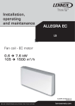
Carisma
The Ultra Quiet Fan Coil
Air Conditioning
Carisma CRC / CRR
Fan Coil Units
Air Conditioning
Sabiana s.p.a. • via Piave, 53 • 20011 Corbetta • Milano • Italy • phone +39.02.97203.1 r.a. / +39.02.97270429 / +39.02.97270576
fax +39.02.9777282 / +39.02.9772820 • www.sabiana.it • [email protected]
B/03/11
COD. A4660100
CRC / CRR - EX - 03/11
Carisma CRC / CRR Fan Coil Units
Quality management systems
ISO 9001 – Cert. n° 0545/4
www.eurovent-certification.com
www.certiflash.com
CONTENTS
The ULTRA quiet fan coil
•Construction (CRC)
•Models (CRC)
•Dimensions,
Weight, Water content (CRC)
•EUROVENT certification (CRC)
•Operation limits (CRC)
•Emission tables (CRC)
•Correction factors table (CRC)
•Water pressure drop (CRC)
Page 4
Page 5
•Construction (CRR)
•Dimensions,
Weight, Water content (CRR)
•EUROVENT certification (CRR)
•Operation limits (CRR)
•Emission tables (CRR)
•Water pressure drop (CRR)
Page 26
•Accessories for CRC/CRR units
•CRYSTALL electrostatic filter (CRC)
•Controls for CRC/CRR units
•FreeSabiana wireless control system
for CRC/CRR units
•CRC/CRR units
with IRC electronic board
•Maxinet management system
for a network of CRC/CRR units
Page 32
Page 39
Page 46
Page 6
Page 10
Page 13
Page 14
Page 24
Page 25
Page 27
Page 28
Page 28
Page 29
Page 31
Page 54
Page 56
Page 60
In line with innovative trends and modern industrial design, the
Carisma fan coil range meets today’s demanding requirements
of performance, size, acoustics, low energy, ease of installation
and maintenance. The Carisma fan coil unit has been designed
around a platform of models, versions and accessories, all
of which have been independently tested and certified by
Eurovent.
Designed around 5 different versions, the extensive range
includes wall and ceiling mounted units, exposed or concealed
with either tangential or centrifugal fan options, delivering one
of the most versatile ranges of fan coils on the market today.
All CRC fan coils with centrifugal fans are equipped with electric
motors which dramatically reduce electrical consumption of
up to 40% comparative to previous models, with 6 speed
motors as standard offering greater flexibility in the selection
of products.
New market trends have also led to an extension of the four
pipe model which now has a two row LTHW battery giving
improved outputs at lower flow and return temperatures.
As a special option, the Carisma range can be fitted with a
patented electronic filter featuring a class D rating according
to Standard UNI 11254, with similar performances to the initial
ones of a traditional mechanical filter featuring a class F9 rating
according to Standard UNI EN 779.
A full range of adjustment and control devices is available
including the FREE innovative patented
wireless system, for rapidly obtaining
correct environmental temperature and
with an investment proportional to
performances, comfort and desired
measurement precision.
The Carisma model is complemented with
a full range of accessories: various types
of adjustment valves, sturdy support feet,
rear covering panel for glass installation,
additional electric heater, auxiliary
condensate pump, fresh air intake
louver, air inlet/outlet diffusers for fitted
installations.
The CRR range with tangential fan combines
a reduced dimension (183mm depth) with a modern
aesthetic that perfectly suit with any kind of furnishing, while
maintaining great performances in terms of sound and consumption.
Sabiana take part to the Eurovent program of fan coil performance certification.
The official figures are published in the web site
www.eurovent-certification.com and in the web site www.certiflash.com.
The tested performances are:
• Cooling total emission at the following conditions:
- Water temperature
+7°C E.W.T.
+12°C L.W.T.
- Entering air temperature
+27°C dry bulb
+19°C wet bulb
• Cooling sensible emission at the following conditions:
- Water temperature
+7°C E.W.T.
+12°C L.W.T.
- Entering air temperature
+27°C dry bulb
+19°C wet bulb
• Heating emission (2 pipe units) at the following conditions:
- Entering water temperature +50°C
- Entering air temperature
+20°C
- Water flow rate as for the cooling conditions
• Heating emission (4 pipe units) at the following conditions:
- Water temperature
+70°C E.W.T.
+60°C L.W.T.
- Entering air temperature
+20°C
• Fan absorption
• Water pressure drop
• Sound power
CRR version
Construction
Outer casing
Made from strong synthetic lateral corners and from galvanized and pre-painted frontal steel sheet.
The plastic top grid has fixed louvres and is reversible in order to distribute the air in two different directions.
Standard colours:
• Lateral corners and top grid: Pantone Cool Grey 1C (light grey)
• Frontal sheet: RAL 9003 (white)
• Other colours on request.
Inner casing
Made from galvanized steel with closed cell insulation.
Filter
Polypropylene cellular fabric regenerating filter.
The filter frame of galvanized steel is inserted into special plastic
sliding guides fastened to the internal structure for easy insertion
and removal of the filter.
Filter presence is highlighted by a plastic front cover featuring the
same colour as the top grid.
Fan assembly
The tangential fan assembly is composed of two fan shrouds: an external one in PVC and an internal one of holed,
shaped steel. The fan has an external diameter of 120mm and is the lenght of the coil. The fins are concave and are
positioned in a spiral shape along the whole lenght of the fan.
Electric motor
The motor is wired for single phase and has three speeds, with capacitor.
The motor is fitted on sealed for life bearings and is secured on anti-vibration and self-lubricating mountings.
Internal thermal protection with automatic reset, protection IP 20, class B.
Coil
It is manufactured from drawn copper tube and the aluminium fins are mechanically bonded onto the tube by an
expansion process. The coil has two 1/2inch BSP internal connections and 1/8 inch BSP air vent and drain.
The coil is not suitable for use in corrosive atmosphere or in environments where aluminium may be subject to
corrosion.
Flow and return pipe connections are situated at the same end on the left side looking at the unit. On request
we can deliver the unit with the connections on the right end side: this must be specified on the order as this
operation can not be carried out on site during installation.
Condensate collection tray
Made from plastic with an “L”-shape fitted on the inner casing.
The outside diameter of the condensate discharge pipe is 15mm.
Accessories and Controls
See pages 32 - 46.
26
CRR version
Dimensions, Weight, Water content
MV
Ø 1/2" F
225
143
A
158
100 71 44 125
100
273
475
630
100 (min.)
530
45
C
133
158
Ø 15 ext.
A
60
60
163
183
Feet optional extra
Dimensions (mm)
Model
1
2
3
4
A
C
Z
670
770
985
1200
354
454
669
884
720
820
1035
1250
PACKAGING
220
600
Z
Weight (kg)
Weight with packaging
Model
Weight without packaging
1
2
3
4
1
2
3
4
13
14
19
22
12
13
18
20
1
2
3
4
0,4
0,5
0,8
1,1
Water content (litres)
Model
27
CRR version
EUROVENT Certification
www.eurovent-certification.com
www.certiflash.com
The following standard rating conditions are used:
COOLING
Entering air temperature +27°C d.b. +19°C w.b.
Water temperature
+ 7°C E.W.T. +12°C L.W.T.
CRR 1
Model
Speed
HEATING
Entering air temperature +20°C
Entering water temperature +50°C
Water flow rate as for the cooling conditions
CRR 2
CRR 3
CRR 4
1 (E)
2 (E)
3 (E)
1 (E)
2 (E)
3 (E)
1 (E)
2 (E)
3 (E)
1 (E)
2 (E)
3 (E)
MIN
MED
MAX
MIN
MED
MAX
MIN
MED
MAX
MIN
MED
MAX
Air flow
m3/h
110
150
180
160
200
250
230
290
360
320
400
500
Cooling total emission (E)
kW
0,63
0,78
0,87
0,95
1,10
1,30
1,31
1,59
1,87
2,00
2,40
2,80
Cooling sensible emission (E)
kW
0,50
0,60
0,70
0,71
0,86
1,01
1,08
1,31
1,53
1,40
1,71
2,05
Heating (E)
kW
0,80
1,00
1,20
1,13
1,32
1,60
1,80
2,20
2,60
2,50
3,00
3,60
Dp Cooling (E)
kPa
6,0
9,0
11,0
11,5
15,5
20,0
4,4
6,3
7,8
11,0
14,5
20,0
Dp Heating (E)
kPa
4,0
5,5
7,0
9,5
12,5
16,5
4,0
5,0
7,0
10,5
14,1
18,8
W
20
22
28
20
22
27
22
26
31
25
30
36
Fan (E)
Sound power (E)
Lw dB(A)
34
37
42
34
39
45
34
39
45
34
40
46
Sound pressure (*)
Lp dB(A)
25
28
33
25
30
36
25
30
36
25
31
37
(E) =Eurovent certified performance.
MIN-MED-MAX =Standard connected speeds.
(*) =The sound pressure levels are 9 dB(A) lower than the sound power levels
and apply to the reverberant field of a 100 m3 room and a reverberation time of 0.5 sec.
Operation limits
Highest water inlet temperature...............................+85°C
Lowest water inlet temperature................................+ 5°C
for entering water temperatures below + 5°C,
contact “SABIANA” technical department
Highest working pressure........................................1000 kPa (10 bars)
Water flow limits (l/h)
Model
CRR 1
CRR 2
CRR 3
CRR 4
Lowest
Highest
70
350
100
550
100
700
150
700
Motor electrical data (max. absorption)
Model
230/1
50Hz
28
W
A
CRR 1
CRR 2
CRR 3
CRR 4
28
0,127
27
0,122
31
0,14
36
0,163
CRR version
Cooling emission of CRR units
Entering air temperature: 27°C – R.H.: 50%
WT: 7/12 °C
WT: 8/13 °C
WT: 10/15 °C
WT: 12/17 °C
Qv
Pc
Ps
Qw Dp(c)
Pc
Ps
Qw Dp(c)
Pc
Ps
Qw Dp(c)
Pc
Ps
Qw Dp(c)
m3/h
kW
kW
l/h
kPa
kW
kW
l/h
kPa
kW
kW
l/h
kPa
kW
kW
l/h
kPa
MAX
180
0,94
0,72
162
8,2
0,84
0,67
144
6,6
0,61
0,59
105
3,7
0,51
0,51
88
2,7
MED
150
0,84
0,63
144
6,7
0,75
0,59
129
5,4
0,54
0,51
93
3,1
0,45
0,45
77
2,2
I
MIN
110
0,68
0,50
117
4,6
0,60
0,47
103
3,7
0,44
0,40
76
2,1
0,36
0,36
62
1,4
CRR
III
MAX
250
1,40
1,03
241
23,1
1,25
0,97
215
18,8
0,93
0,85
160
11,0
0,74
0,74
127
7,3
MED
200
1,19
0,86
205
17,2
1,06
0,81
182
14,0
0,79
0,71
136
8,3
0,62
0,62
107
5,3
I
MIN
160
1,02
0,73
175
13,2
0,91
0,69
157
10,8
0,69
0,60
119
6,4
0,53
0,53
91
4,0
CRR
III
MAX
360
2,02
1,49
347
9,0
1,80
1,41
310
7,3
1,33
1,23
229
4,2
1,07
1,07
184
2,8
II
MED
290
1,73
1,26
298
6,8
1,54
1,18
265
5,5
1,14
1,03
196
3,2
0,90
0,90
155
2,1
I
MIN
230
1,41
1,01
243
4,8
1,26
0,95
217
3,9
0,94
0,83
162
2,3
0,73
0,73
126
1,5
III
MAX
500
3,02
2,18
519
23,0
2,70
2,05
464
18,8
2,03
1,79
349
11,2
1,58
1,58
272
7,1
II
MED
400
2,55
1,82
439
17,1
2,28
1,71
392
14,0
1,72
1,49
296
8,4
1,31
1,31
225
5,1
I
MIN
320
2,14
1,51
368
12,6
1,92
1,42
330
10,3
1,45
1,23
249
6,2
1,09
1,09
187
3,7
Model
Speed
CRR
III
II
II
1
2
3
CRR
4
Cooling emission of CRR units
Entering air temperature: 26°C – R.H.: 50%
WT: 7/12 °C
Qv
Qw Dp(c)
Pc
Qw Dp(c)
Pc
kW
l/h
kPa
0,67
143
6,6
kW
kW
l/h
kPa
0,73
0,63
126
5,1
0,59
127
5,4
0,65
0,55
112
4,2
0,60
0,47
103
3,7
0,52
0,44
89
250
1,24
0,97
200
1,05
0,81
213
18,7
1,09
0,91
181
14,0
0,93
0,76
160
0,91
0,69
157
10,8
0,80
0,64
138
MAX
360
MED
290
1,79
1,41
308
7,3
1,57
1,32
1,53
1,18
263
5,5
1,34
1,11
I
MIN
III
MAX
230
1,25
0,95
215
3,9
1,10
0,89
500
2,68
2,06
461
18,8
2,37
1,93
II
MED
400
2,27
1,71
390
14,0
2,00
I
MIN
320
1,91
1,42
329
10,3
1,69
Speed
CRR
III
Ps
3
m /h
kW
MAX
180
0,83
II
MED
150
0,74
I
MIN
110
III
MAX
II
MED
I
MIN
CRR
III
II
CRR
1
CRR
2
3
4
WT: 12/17 °C
Ps
Qw Dp(c)
Pc
kW
kW
l/h
kPa
0,56
0,56
96
3,2
0,49
0,49
84
2,5
2,9
0,39
0,39
67
187
14,8
0,81
0,81
160
11,1
0,65
0,65
8,6
0,57
270
5,7
230
4,3
189
408
1,60
344
1,33
291
Ps
Qw Dp(c)
kW
kW
l/h
kPa
0,47
0,47
81
2,3
0,41
0,41
71
1,8
1,7
0,32
0,32
55
1,2
139
8,6
0,68
0,68
117
6,2
112
5,9
0,57
0,57
98
4,5
0,55
98
4,6
0,48
0,48
83
3,4
1,17
1,17
201
3,4
0,98
0,98
169
2,4
0,98
0,98
169
2,5
0,82
0,82
141
1,8
3,1
0,78
0,76
134
1,6
0,67
0,67
115
1,2
14,9
1,68
1,66
289
8,0
1,44
1,44
248
6,1
11,1
1,43
1,38
246
6,1
1,20
1,20
206
4,4
8,2
1,21
1,14
208
4,5
0,99
0,99
170
3,2
Legend
Correction factors for different R.H.
R.H.
WT:
7/12°C
8/13°C
10/15°C
12/17°C
48%
Pc
Ps
Pc
Ps
0,95
1,00
0,90
1,00
0,94
1,00
0,88
1,00
1,00
1,00
1,00
1,00
1,00
1,00
1,00
1,00
46%
WT: 10/15 °C
Ps
Model
Pc
WT: 8/13 °C
WT
= Water temperature
Speed=Fan speed
Pc
= Cooling total emission
MAX =High speed
Ps
= Cooling sensible emission
MED =Medium speed
Qw
= Water flow
MIN
=Low speed
Qv
=Air flow
Dp(c)= Water pressure drop
29
CRR version
Cooling emission of CRR units
Entering air temperature: 25°C – R.H.: 50%
WT: 7/12 °C
WT: 8/13 °C
WT: 10/15 °C
WT: 12/17 °C
Qv
Pc
Ps
Qw Dp(c)
Pc
Ps
Qw Dp(c)
Pc
Ps
Qw Dp(c)
Pc
Ps
Qw Dp(c)
m3/h
kW
kW
l/h
kPa
kW
kW
l/h
kPa
kW
kW
l/h
kPa
kW
kW
l/h
kPa
MAX
180
0,73
0,63
126
5,2
0,62
0,59
107
3,9
0,51
0,51
88
2,8
0,42
0,42
72
1,9
MED
150
0,65
0,55
112
4,2
0,55
0,52
95
3,2
0,45
0,45
77
2,2
0,37
0,37
64
1,5
I
MIN
110
0,52
0,44
89
2,9
0,45
0,41
77
2,2
0,36
0,36
62
1,4
0,29
0,29
50
1,0
CRR
III
MAX
250
1,09
0,91
187
14,9
0,94
0,85
162
11,4
0,75
0,75
129
7,4
0,61
0,61
105
5,2
MED
200
0,93
0,76
160
11,1
0,80
0,71
138
8,5
0,62
0,62
107
5,4
0,51
0,51
88
3,8
I
MIN
160
0,80
0,64
138
8,6
0,69
0,60
119
6,6
0,53
0,53
91
4,0
0,43
0,43
74
2,8
CRR
III
MAX
360
1,57
1,32
270
5,7
1,34
1,23
230
4,3
1,07
1,07
184
2,9
0,88
0,88
151
2,0
II
MED
290
1,34
1,11
230
4,4
1,15
1,03
198
3,3
0,90
0,90
155
2,1
0,74
0,74
127
1,5
I
MIN
230
1,10
0,89
189
3,1
0,95
0,83
163
2,4
0,73
0,73
126
1,5
0,60
0,60
103
1,0
III
MAX
500
2,36
1,93
406
15,0
2,04
1,80
351
11,5
1,58
1,58
272
7,2
1,30
1,30
224
5,1
II
MED
400
2,00
1,61
344
11,2
1,73
1,50
298
8,6
1,32
1,32
227
5,2
1,09
1,09
187
3,7
I
MIN
320
1,68
1,33
289
8,2
1,46
1,24
251
6,4
1,09
1,09
187
3,8
0,90
0,90
155
2,7
Model
Speed
CRR
III
II
II
1
2
3
CRR
4
Legend
Correction factors for different R.H.
R.H.
WT:
7/12°C
8/13°C
10/15°C
12/17°C
48%
Pc
Ps
Pc
Ps
0,95
1,00
0,90
1,00
0,94
1,00
0,88
1,00
1,00
1,00
1,00
1,00
1,00
1,00
1,00
1,00
46%
WT
= Water temperature
Speed=Fan speed
Pc
= Cooling total emission
MAX =High speed
Ps
= Cooling sensible emission
MED =Medium speed
Qw
= Water flow
MIN
=Low speed
Qv
=Air flow
Dp(c)= Water pressure drop
Heating emission of CRR units
Entering air temperature: 20°C
WT: 70/60 °C
Qv
Ph
Qw Dp(c)
3
m /h
kW
l/h
MAX
180
2,03
MED
150
1,78
I
MIN
110
1,40
CRR
III
MAX
250
II
MED
200
I
MIN
CRR
III
MAX
II
CRR
Ph
Qw Dp(c)
kPa
kW
l/h
175
8,9
1,54
153
7,0
1,35
120
4,6
1,06
2,69
231
18,1
2,25
194
13,2
160
1,91
164
360
4,57
393
MED
290
3,80
327
I
MIN
230
3,02
III
MAX
500
6,12
II
MED
400
I
MIN
320
Model
Speed
CRR
III
II
1
2
3
4
WT: 60/50 °C
Ph
Qw Dp(c)
kPa
kW
l/h
132
5,7
1,06
116
4,5
0,93
91
2,9
2,05
176
1,72
148
9,9
1,46
8,8
3,49
6,3
260
526
5,08
437
4,22
363
Qw Dp(c)
kPa
kW
l/h
91
3,0
1,24
80
2,4
1,09
0,73
63
1,6
11,6
1,42
122
8,5
1,19
102
126
6,4
1,01
300
5,6
2,41
2,90
249
4,1
2,01
4,2
2,31
199
2,7
20,6
4,69
403
13,3
14,8
3,89
335
10,7
3,24
279
WT
= Water temperature
Speed=Fan speed
Ph
= Emission
MAX =High speed
Qw
= Water flow
MED =Medium speed
30
WT: 50/45 °C
Ph
Legend
Dp(c)= Water pressure drop
WT: 50/40 °C
MIN
=Low speed
Qv
=Air flow
WT: 45/40 °C
Ph
Qw Dp(c)
kPa
kW
l/h
kPa
213
13,3
1,00
172
9,3
187
10,6
0,88
151
7,4
0,85
146
6,9
0,69
119
4,8
6,3
1,64
282
27,2
1,33
229
19,1
4,6
1,37
236
19,8
1,11
191
13,9
87
3,5
1,17
201
14,9
0,95
163
10,5
207
3,0
2,79
480
13,2
2,26
389
9,3
173
2,2
2,32
399
9,5
1,88
323
6,7
1,60
138
1,5
1,84
316
6,4
1,49
256
4,5
3,26
280
7,2
3,74
643
30,9
3,03
521
21,7
9,6
2,71
233
5,2
3,10
533
22,3
2,52
433
15,7
6,9
2,26
194
3,8
2,58
444
16,1
2,09
359
11,3
CRR version
Water pressure drop
Dp - kPa
30
2
4
20
10
9
8
7
1
6
5
3
4
Water
flow (l/h)
3
60
80
100
200
300
The water pressure drop figures
refer to a mean water temperature of 10°C;
for different temperatures,
multiply the pressure drop figures
by the correction factors K.
400
600
°C
K
800
20
30
40
50
60
70
80
0,94 0,90 0,86 0,82 0,78 0,74 0,70
31
Accessories for CRC / CRR units
VBP
main coil 3 way valve
Control valve kit:
3 way valve, ON-OFF,
with electric motor and mounting kit
with micrometric lockshield valve.
Version
CRC / CRR
Model
MV – MO – MVB – IV – IO
Dimensions (mm)
Mod.
1÷5
CRC 6–7
8–9
CRR 1÷4
HEARTH
Dimensions ± 10 mm
Valve
Micrometric lockshield valve
Code
A
B
C
D
E
DN
(Ø)
Kvs
DN
(Ø)
Kvs
FITTED
NOT FITTED
25
85
190
290
105
15
1/2”
1,6
15
1/2” F
2
9066561H
9066560H
25
85
190
290
105
20
3/4”
2,5
15
1/2” F
2
9060471H
9060474H
50
120
185
290
105
20
3/4”
2,5
15
1/2” F
2
9060471H
9060474H
15
90
200
315
95
15
1/2”
1,6
15
1/2” F
2
9066561H
9066560H
VBA
additional coil 3 way valve
Control valve kit:
3 way valve, ON-OFF,
with electric motor and mounting kit
with micrometric lockshield valve.
Version
CRC
Model
MV – MO – MVB – IV – IO
Mod.
1÷7
8–9
HEARTH
Dimensions (mm)
Dimensions ± 10 mm
Valve
Micrometric lockshield valve
Code
A
B
C
D
DN
(Ø)
Kvs
DN
(Ø)
Kvs
FITTED
NOT FITTED
120
195
240
340
15
1/2”
1,6
15
1/2” F
2
9060472H
9060475H
135
200
235
330
15
1/2”
1,6
15
1/2” F
2
9060472H
9060475H
Kvs 2
Dp - kPa
Kvs 2,5
Kvs 1,6
40
30
20
10
9
8
7
6
5
4
3
2
Water
flow (l/h)
1
100
32
200
300 400
600 800 1000
2000 3000 4000
Accessories for CRC / CRR units
VS
simplified kit for 3 way valve
(concealed model only)
3 way valve, (ON-OFF)
with electric motor and mounting kit.
Valve with flat connection
without micrometric lockshield valve.
Version
CRC
Model
IV – IO
Dimensions ± 10 mm
Mod.
1÷5
6–7
8–9
Additional
Main
Dimensions (mm)
Additional
Main
C
Valve
Valve
Code
A1
A2
B1
B2
152
270
185
330
116
15 1/2” 1,6 9066571H
9066570H
152
268
185
330
124
20 3/4” 2,5 9060484H
9060481H
177
270
210
327
124
20 3/4” 2,5 9060484H
9060481H
DN (Ø) Kvs
FITTED
NOT FITTED
Code
DN (Ø) Kvs
FITTED
NOT FITTED
15 1/2” 1,6 9060483H
9060480H
V2
2 way valve
for main and additional coil
Control valve kit:
2 way valve, ON-OFF,
with electric motor and mounting kit.
Version
CRC / CRR
Model
MV – MO – MVB – IV – IO
Dimensions ± 10 mm
Main
Dimensions (mm)
Mod.
1÷5
CRC 6–7
8–9
CRR 1÷4
Main
Additional
Valve
DN (Ø) Kvs
Additional
Code
Valve
A
C
D
E
H
149
180
386
186
456
15 1/2” 1,7 9060476H
9060478H
150
181
438
186
456
20 3/4” 2,8 9060477H
9060479H
176
175
422
210
440
20 3/4” 2,8 9060477H
9060479H
143
178
448
–
–
15 1/2” 1,7 9060476H
9060478H
FITTED
Kvs 1,7
Dp - kPa
HEARTH
Kvs 1,6
NOT FITTED
Code
DN (Ø) Kvs
FITTED
15 1/2” 1,7 9060476H
–
–
–
–
NOT FITTED
9060478H
–
Kvs 2,5
Kvs 2,8
40
30
20
10
9
8
7
6
5
4
3
2
Water
flow (l/h)
1
100
200
300 400
600 800 1000
2000 3000 4000
33
Accessories for CRC / CRR units
BEL electric heater
(not available with Crystall)
1 PHASE 230V
Electric heater with integral:
safety thermostat and relay control.
Version
CRC
Model
MV – MO – MVB – IV – IO
Size
1
Watt
650
Code
2
1000
3–4
600
400
1500
900
5–6
600
2000
1250
7–8–9
750
2500
1500
1000
9066491 9066492 9066482 9066472 9066493 9066483 9066473 9066495 9066485 9066475 9066497 9066487 9066477
Extension condensate collection tray to cover valve assembly
BSV
BSO
(for vertical units)
(for horizontal units)
CRC
Model
MO – IO (horizontal)
Version
CRC
Connection
Model
MV – MVB – IV (vertical)
MV
Type
BSO-SX
BSO-DX
Code
6060400
6062125
Code
6060402
6060403
CRR
SCR plastic condensate drain pipe with fast connection
(allows correct condensate drain)
Version
CRC
Model
MO – IO
Code
6060420
PAP feet
Version
CRC / CRR
Model
MV
Size
CRC
CRR
1
2
3–4
5–6
7
8–9
1
2
3
4
–
–
34
Version
L
Code
CRC
CRR
330
9066351
9068101
430
9066351
9068101
645
9066351
9068101
860
9066351
9068101
1119
9066351
–
1119
9066358
–
side
LEFT
RIGHT
46
CONTROL
IDENTIFICATION
CONTROL CODES
Installation
of bimetallic low temperature CUT-OUT thermostat (TMM)
Installation
of electronic low temperature CUT-OUT thermostat (TME)
Room thermostat for fan and electric heater control
(not for CRYSTALL)
Room thermostat for chilled water valve (SUMMER)
and electric heater (WINTER) control
(in winter only the electric heater is working)
Simultaneous
thermostatic control of the valves and fan
Room thermostat for fan control (ON-OFF)
Room thermostat for 1 valve control (2 pipe installation)
Room thermostat for 2 valve control (4 pipe installation)
Automatic Summer/Winter switch
with neutral zone for 4 pipe installation with 2 valves
Remote centralized Summer/Winter switch
or by an automatic change-over fitted on the water pipe
Manual 3 speed switch
Manual/Automatic 3 speed selection
Summer/Winter switch
ON-OFF switch
for CRYSTALL electrostatic filter or electric heater
ON-OFF switch
CONTROL
OPERATIONS
MO – IV – IO
CRC
MV – MVB
CRC / CRR
Control functions for CRC / CRR units
Electrical diagrams are shown on the installation, use and maintenance manual
CB-AU-IAQ
9066307
CB-R-IAQ
9066306
CB-IAQ
9066305
CB-AU
9066303
CB-C
9066302
CB-T
9066301
CB
9066300
TMO-T-AU-IAQ
9063023
TMO-T-IAQ
9063021
MO-3V-IAQ
9063020
T2T
9060174
TMO-DI
9060165
TMO-503-SV2
9060173
TMO-503-S
9060171
TMO-T-AU
9060164
TMO-T
9060161
CR-T
9066330
MO-3V
9060160
Electronic controls
to be fitted on MV-MVB units (CRC / CRR)
Identification
Code
CB
9066300
• ON-OFF switch and 3 speed switch.
• Without thermostatic control.
• It allows to control the low temperature cut-out thermostat (TMM).
Identification
Code
CB-T
9066301
• ON-OFF switch.
• 3 speed switch.
• Summer/Winter switch.
• Electronic room thermostat for fan or valves control (ON-OFF).
• It allows to control the low temperature cut-out thermostat (TMM).
• It allows to control the chilled water valve (ON-OFF) and the electric heater (BEL) only in case that
hot water is not used in winter (otherwise please use CB-R-IAQ control with on/off switch for the
electric heater).
Identification
Code
CB-C
9066302
• ON-OFF switch.
• 3 speed switch.
• It allows to control the summer or winter cycle with centralized and remote switch, or an automatic
change-over fitted on the water pipe (for 2-tube installations only).
• Electronic room thermostat for fan or valves control (ON-OFF).
• It allows to control the low temperature cut-out thermostat (TME).
• It allows to control the chilled water valve (ON-OFF) and the electric heater (BEL) only in case that
hot water is not used in winter (otherwise please use CB-R-IAQ control with on/off switch for the
electric heater).
Identification
Code
CB-AU
9066303
• Manual or automatic speed switch: on Auto Mode there is the automatic speed selection in accordance
to the difference between room temperature and setpoint. When the setpoint is reached the fan go
on OFF.
• Summer/Winter switch.
• Electronic room thermostat for valve(s) control (ON-OFF).
• Simultaneus thermostatic control of the valves and fan.
• It allows to control the low temperature cut-out (TME).
• It allows to control the chilled water valve (ON-OFF) and the electric heater (BEL) only in case that
hot water is not used in winter (otherwise please use CB-AU-IAQ control with on/off switch for the
electric heater).
• It allows to control the summer/winter cycle with a centralized and remote switch or with an automatic
change-over fitted on the water pipe (for 2-tube installations only).
N.B.: with 4 pipe installations and continuous chilled and hot water supply, it allows the automatic summer/
winter change-over in accordance to the room temperature (-1°C = Winter, +1°C = Summer, Neutral
Zone 2°C).
47
Electronic control accessories
for CRC / CRR units
TME low temperature cut-out thermostat
To be fitted between the coil fins; when connecting the control,
the TME probe cable must be separated from the power supply wires.
To be used with the following controls:
CB-C, CB-AU, TMO-T, TMO-T-AU, TMO-DI and corresponding IAQ controls.
It stops the fan when
the water temperature is lower than 38°C
and it starts the fan when is higher than 42°C.
Version
CRC / CRR
Model
MV – MO – MVB – IV – IO
Code
3021091
TMM low temperature cut-out thermostat
To be installed in contact with the hot water circuit.
To eliminate cold air blow.
Installed by the installing engineer.
To be used with the following controls:
CB, CB-T, CB-IAQ, MO-3V, CR-T, MO-3V-IAQ.
For units working on heating only.
It stops the fan when
the water temperature is lower than 30°C
and it starts the fan when is higher than 38°C.
RED
BROWN
Version
CRC / CRR
Model
MV – MO – MVB – IV – IO
Code
9053048
Change-Over CH 15-25
Automatic summer/winter switch
to be installed in contact with the water circuit.
For 2-tube installations only
(not to be used with 2 way valve).
To be used with the following controls:
CB-C, CB-AU, TMO-T, TMO-T-AU, TMO-DI.
RED
BLACK
Version
CRC / CRR
Model
MV – MO – MVB – IV – IO
Code
9053049
53
FreeSabiana wireless control system
for CRC / CRR units
FreeSabiana
Free Sabiana is an innovative, fully wireless, electronic system for use with
fan coil units, based on radio communication.
This technology provides installation flexibility and a more accurate
measurement of the room temperature. The probe can be moved until
the most suitable position is found, without the worry of changes in the
environment layout and of its furniture and also without mounting it on a wall.
If a new fan coil unit is added, no electrical wiring for the control system is
required: just define the control unit and the probe which regulates it. The improved measurement accuracy derives
from the possibility to position the probe near the typical location of the user: this enables to keep the temperature
exactly at the required value with more energy savings compared with a traditional measurement system.
Transmission is based on communication protocol IEE802.15.4, the most suitable way to transmit a relatively low
amount of information with very low consumption and high reliability.
The system has been certified by a leading independent body, officially recognized by the EU authorities and its
sale has been authorized in all the EU and EFTA countries.
Main components
Free Sabiana includes 3 main components:
Description
❍
A remote control which features a button panel and
LCD display and can be wall-mounted or positioned
on a dedicated table support.
It enables the control of all the operating variables of
the fan coil units in different configurations. The control
is battery powered.
The temperature and the operating speed of the fan
coil unit are set with two large buttons featuring user
friendly graphics.
Identification
Code
Free-Com
9060572
Remote control
Control unit with support
Description
❍
A power unit to be installed on the fan coil (fan coil
interface).
It controls the fan and the valves of the fan coil. The
power unit is connected to the electric supply.
The power unit receives the information required to
control the fan coil both from the remote control and
locally, such as the temperature of the coil.
Identification
Code
Power unit fitted on the unit
Free-Upm
9060571
Power unit not fitted on the unit
Free-Ups
9060570
Identification
Code
Free-Sen
9060573
Power unit
Description
❍
A room temperature probe, which can be wallmounted or positioned on a dedicated table support.
It is a battery powered device, able to measure the air
temperature in the spot where it is positioned, generating
temperature information which is communicated to the
other devices.
Temperature probe
Probe with support
54
FreeSabiana wireless control system
for CRC / CRR units
Main features of the remote control
The control enables:
❍ Fan coil on/off switching
❍ Fan speed selection (high - medium - low - automatic)
❍ Summer/winter operation selection
❍ Valve on/off
❍ Real time clock setting
❍ Temperature setting
❍ Daily switch on/off setting (timer function)
❍ Enable/disable the timer function
❍ Activation of the (eventual) electrostatic filter
❍ Activation of the (eventual) electric heater
Main information displayed:
1
2
3
4
5
6
7
1
2
3
7
4
5
6
On-off status
Summer operation
Winter operation
Automatic season change
Electric heater
Crystall filter
Room temperature
(with decimal accuracy)
8
9
10
11
12
13
12
9
10
11
8
Fan operating speed
Required/measured temperature
Timer
Clock
Transmission signal
Battery level
13
Main features of the power unit to be installed on the fan coil
The power unit controls
the fan and the valves of the fan coil.
The power unit receives the information
required to control such units
both from the remote control and locally.
It enables the following main actions:
❍ Fan on/off at a set speed
❍ Fan speed change (fan on/off)
❍ Water valve/s on/off (1 valve for 2 tube system - 2 valves for 4 tube system)
❍ Fan speed change operating the water valve/s
❍ Control of the electric resistance as main heating unit or as integration to the battery supplied with hot water
❍ Control of the operation of the electrostatic filter (in parallel to the fan)
❍ Management of the dead zone function for 4-tube systems
❍ Available functional inputs: • Consent for remote on/off
• Consent for remote Summer/Winter switch (centralized)
• Consent for the activation of the Energy Saving function with setting change
• Minimum probe
• Probe for season change
Main features of the temperature probe
This device is able to measure
the temperature of the air in the spot
where it is positioned and to transmit it
by means of radio communication to
the other devices in the system.
It is battery powered and can be
freely positioned in the area
to be air-conditioned.
Display:
❍ Measured environment temperature
❍ Transmission signal
❍ Clock
❍ Battery status
55
CRC / CRR units with IRC electronic board
Description
Identification
Code
IRC-M
9060175
Infra-red remote control with electronic board fitted on the unit (MV-MO-MVB only)
Infra-red remote control with electronic board not fitted on the unit (IV-IO only)
IRC-S
9060176
ETN +/-3°C with electronic board fitted on the unit
IRC-ETN-M
9060166
ETN +/-3°C with electronic board not fitted on the unit
IRC-ETN-S
9060167
The Carisma units can be supplied with a micro-processor managing system operated by an infra-red remote control
with liquid crystall display or by a wall-mounted IRC-ETN control.
Integral with the unit is an electronic board with RS485 communicating connection which can control up to 20 units
connected between them. The electronic board is of master/slave mode and the serial communicating connection
allows the serial connection; in the master/slave connection of more units, it is recommended to install the infra-red
receiver on the master unit.
IRC controls are not suitable for Crystall electronic filter and BEL electric heater.
The units with IR control are supplied with room temperature probe and
water temperature probe (cut-out thermostat).
The infra-red remote control
features the following functions:
-Temperature set.
-Fan speed switch
with possible automatic speed selection.
-24 hours on/off program.
-ON/OFF cooling valve control.
-ON/OFF heating valve control.
-Control of the valves only or of the valves and the fan together.
-Valve control of 2 or 4 pipe systems
with winter/summer switch on the infra-red control.
-Valve control of 4 pipe systems
with automatic heating/cooling mode selection with 2°C dead zone.
-Activating the sensor connected to the T3 contact of the board (non active
in the standard configuration), it works like a cut-out thermostat: fitted
between the coil fins it stops the fan when the water temperature is lower
than 38°C and it starts the fan when the water temperature reaches 42°C.
The wall-mounted control
features the following functions:
-Switch the appliance ON and OFF.
-Set the fan speed.
-Set the range of temperature settings
(default +/- 3 °C, modifiable on site up to +/- 9°C).
-Modify the set point determined by the system by a value of +/- X°C.
The Maxinet system (see the following pages) can set the operating mode,
the set point and all other operating parameters of the unit, as well as
display the settings made by the user. The Maxinet system always has
priority over the ETN controller. For the correct use of the system, also see
the manual for the Fan-coil with remote control and the Maxinet supervision
program.
56
CRC / CRR units with IRC electronic board
IRC electronic board
The electronic board, fitted inside the electrical panel, can manage different control modes so as to best satisfy the
requirements of the installation. These modes are selected by suitably positioning the configuration dipswitches,
which define the following main functions:
•2 pipe / 4 pipe system
•Operation without / with remote control
IRC
•Continuous ventilation
electronic board
•Close valve
and stop fan in cooling mode (autofan function)
•Close valve
and stop fan in heating mode (autofan function)
•Close valve and stop fan
in both cooling and heating mode (autofan function)
The autofan function allows the simultaneous ON/OFF control of the water
valve and the fan, while at the same time optimising the operation of the unit.
When reaching the set point, the controller closes the water valve (valve OFF)
and only 3 minutes later stops the fan, so as to correctly compensate for the valve
closing time. To prevent the air probe from measuring an incorrect temperature, when the
fan is OFF the controller runs a number of fan ON cycles to annul the effect of any stratification
of the air in the room.
In two pipe systems, a water probe (T2 accessory) can be installed on
the supply pipe to the unit upstream of the water valve. Based on
the temperature read in this section of the pipe, the device will
select either cooling or heating operation.
The electronic board also features a contact for connection to a
window switch or remote enabling signal. When the contact is
closed, the unit can operate, when the contact is open, the unit
stops. The same contact can be used for starting and stopping the
unit from an external timer or any other remote switching device.
In addition, a series of units can be switched ON or OFF at the same
time, by using a flip-flop switch connected to the terminals present on the
board.
Sensors that require a 12 Volt power supply, for
example occupancy sensors, can be connected to
other terminals on the electronic board and then to
the ON/OFF contacts. The board is able to power
external sensors with a maximum current of 60 mA.
Installation example
with infra-red remote control
57
CRC / CRR units with IRC electronic board
A group of Carisma units with IRC electronic board can be connected via a serial link and can consequently be
managed at the same time by just one infra-red remote control or IRC-ETN wall-mounted control. Using the special
jumper present on the board, one unit must be configured as the master, and all the others as slaves. It is clear that
the remote control must be pointed at the receiver on the master unit. To avoid problems, it is recommended to
install and connect the receiver only on the master unit.
With infra-red remote control
One control for more units
(20 units max.)
One control for each unit
(Maximum
total length of the connection cable
= 800 m)
With ETN
One control for more units
(20 units max.)
One control for each unit
(Maximum
length of the connection cable
= 20 m)
(Maximum
total length of the connection cable
= 800 m)
T2 Change-Over for infra-red remote control (accessory)
Identification
Code
T2
9079103
Suitable for units with infra-red remote control only.
The NTC sensor, if connected to the T2 contact of the board, works like a change-over: fitted in contact to the supply
pipe it controls automatically the winter/summer switch in accordance to the water temperature.
58
CRC / CRR units with IRC electronic board
Multifunction control
Another option available for the serial communication between the
units is the possibility to connect up to 60 Carisma units in series (the
maximum length of the connection cable must not exceed 800 m)
and manage them with just one wall-mounted intelligent PCR-DI
controller. The wall-mounted controller can be used to set the
operating mode for each individual unit connected, display the
operating conditions of each individual unit, and set the ON/OFF
time sets for each day of the week. If more than 60 units need to
be connected, two or more wall-mounted intelligent controllers must
be used. Each wall-mounted controller only manages the units it is
connected to.
Identification
Code
PCR-DI
9079102
The PCR-DI control is used to manage a series of fan coils, up to
a maximum of 60 units, from one single control point. The PCR-DI
control communicates via a serial line with all the units connected,
with the possibility of controlling them all together or individually.
In fact, the unique address of each individual fan coil means that
all the units can be called at the same time, or the individual unit
called, to perform the following functions:
-display the current
operating mode, the fan speed, the set point
-display the room temperature
measured on the individual unit
-turn all the units ON and OFF at the same time
or alternatively each unit individually
-change the operating mode
(fan only, heating, cooling, automatic changeover)
-change the set point
Each function can then be sent to all the units connected, or alternatively to each
individual unit.
Different set points or operating modes can be set for each individual unit.
The PCR-DI panel can also be used for the time management of the units over the week.
Two on times and two off times can be set on the units for each day of the week.
The weekly programming mode can be stopped at any time, returning to the manual setting and then weekly
programming mode can subsequently be started again.
59
Maxinet management system
for a network of CRC / CRR units
Maxinet program for managing a network of IR hydronic terminals
Maxinet is a centralised control system for networks of IR hydronic
terminals, based on software that runs on Windows XP Professional
Service Pack 2.
The Maxinet software offers a practical and economical solution for
managing the terminals, with the simple click of the mouse.
The main characteristics include simplicity of use, an extremely complete
and functional weekly program, and the possibility to access the historical
operating data for each individual appliance connected.
The program exploits all the potential of our appliances with remote
controls, representing an addition to the latter.
The Maxinet program is a control tool that can be used as a replacement
for the remote control, or in parallel, however with the possibility of setting
the priority, that is, the settings made using Maxinet can have priority
over those made using the remote control.
The program can be used to:
- create uniform logical blocks (groups of units on individual floors, in offices or rooms).
- save weekly programs configured for different types of operation (summer, winter, mid seasons, closing periods
etc.); these can then be recalled and activated with a simple click of the mouse.
Weekly on/off cycles can be set for individual units or groups of units.
- set the operating conditions for each individual unit or groups of units (operating mode, fan speed, temperature
setting).
- set the set point limits for each individual unit or groups of units.
- switch each individual unit or groups of units on or off.
The “Weekly Program” can be used to set the unit operating parameters for each day of the week.
Up to 20 different weekly programs can be set.
Time bands are available for each day of the week.
The time and the type of operation to be performed by the unit can be set for each band.
The time and the operating parameters can then be displayed before being sent to the unit and implemented.
60
Maxinet management system
for a network of CRC / CRR units
One especially useful function of the weekly program is to have the program to carry out timed checking routines to
identify whether the operating mode or temperature setting have been modified on the terminals, for example using
the local remote control. If activated, the routine will reset all the unit operating parameters to the values set in the
weekly program.
Selection of the view mode
Selection of the different units
Main menu
Working mode
of every unit
Control
parameters
Floors/sections
selection
Controls
Unit
The main program screen can display and
interact with the entire network of units. An
individual unit, a group of units or the entire
network can be called so as to make
modifications to the operating mode and
the set point. The user can then check the
operating status of each individual unit, read
the room temperature, the coil temperature
and the operating status of the condensate
drain pump or any alarms.
Room (name/number)
Set
Temperature
Address
Fan
AutoFan
Mode
Cooling
Heating
Auto
Fan only
OFF
PC Maxinet
Software
Connection
of a Carisma network
of more than 60 units
RS 485 serial connection cable
Shielded cable to be used:
Belden 9841, RS-485, 1x2x24 AWG SFTP, 120 Ohm
61
Accessories MaxiNet 7 for CRC / CRR units
Identification
Code
S08R
9079105
In addition to the air-conditioning units, MaxiNet can also work with
general output cards.
Each card contains 8 outputs which can be connected to “On / Off”
devices.
Inserting a new output card can be done through the regular units
setting.
Handling the existing output cards is done through the output cards’
menu, which can be loaded from the working screen’s menu bar.
In the menu, choose the “General Outputs Cards” title.
The Out-Put card can be connected in a Maxinet network and controlled by the software. Up to 10 cards can used.
The descriptions and illustrations provided in this publication are not binding:
Sabiana reserves the right, whilst maintaining the essential characteristics of the types described
and illustrated, to make, at any time, without the requirement to promptly update
this piece of literature, any changes that it considers useful
for the purpose of improvement or for any other manufacturing or commercial requirements.
62
CONTENTS
The ULTRA quiet fan coil
•Construction (CRC)
•Models (CRC)
•Dimensions,
Weight, Water content (CRC)
•EUROVENT certification (CRC)
•Operation limits (CRC)
•Emission tables (CRC)
•Correction factors table (CRC)
•Water pressure drop (CRC)
Page 4
Page 5
•Construction (CRR)
•Dimensions,
Weight, Water content (CRR)
•EUROVENT certification (CRR)
•Operation limits (CRR)
•Emission tables (CRR)
•Water pressure drop (CRR)
Page 26
•Accessories for CRC/CRR units
•CRYSTALL electrostatic filter (CRC)
•Controls for CRC/CRR units
•FreeSabiana wireless control system
for CRC/CRR units
•CRC/CRR units
with IRC electronic board
•Maxinet management system
for a network of CRC/CRR units
Page 32
Page 39
Page 46
Page 6
Page 10
Page 13
Page 14
Page 24
Page 25
Page 27
Page 28
Page 28
Page 29
Page 31
Page 54
Page 56
Page 60
In line with innovative trends and modern industrial design, the
Carisma fan coil range meets today’s demanding requirements
of performance, size, acoustics, low energy, ease of installation
and maintenance. The Carisma fan coil unit has been designed
around a platform of models, versions and accessories, all
of which have been independently tested and certified by
Eurovent.
Designed around 5 different versions, the extensive range
includes wall and ceiling mounted units, exposed or concealed
with either tangential or centrifugal fan options, delivering one
of the most versatile ranges of fan coils on the market today.
All CRC fan coils with centrifugal fans are equipped with electric
motors which dramatically reduce electrical consumption of
up to 40% comparative to previous models, with 6 speed
motors as standard offering greater flexibility in the selection
of products.
New market trends have also led to an extension of the four
pipe model which now has a two row LTHW battery giving
improved outputs at lower flow and return temperatures.
As a special option, the Carisma range can be fitted with a
patented electronic filter featuring a class D rating according
to Standard UNI 11254, with similar performances to the initial
ones of a traditional mechanical filter featuring a class F9 rating
according to Standard UNI EN 779.
A full range of adjustment and control devices is available
including the FREE innovative patented wireless system, for rapidly obtaining correct
environmental temperature and with an
investment proportional to performances,
comfort and desired measurement
precision.
The Carisma model is complemented with
a full range of accessories envisioned
in a system with fan coils, among which,
various types of adjustment valves, sturdy
support feet, rear covering panel for glass
installation, additional electric heater,
auxiliary condensate pump, fresh air
intake louver, air inlet/outlet diffusers for
fitted installations.
The CRR range with tangential fan combines
a reduced dimension (183mm depth) with a modern
aesthetic that perfectly suit with any kind of furnishing, while
maintaining satisfactory performances in terms of sound and consumption.
Sabiana take part to the Eurovent program of fan coil performance certification.
The official figures are published in the web site
www.eurovent-certification.com and in the web site www.certiflash.com.
The tested performances are:
• Cooling total emission at the following conditions:
- Water temperature
+7°C E.W.T.
+12°C L.W.T.
- Entering air temperature
+27°C dry bulb
+19°C wet bulb
• Cooling sensible emission at the following conditions:
- Water temperature
+7°C E.W.T.
+12°C L.W.T.
- Entering air temperature
+27°C dry bulb
+19°C wet bulb
• Heating emission (2 pipe units) at the following conditions:
- Entering water temperature +50°C
- Entering air temperature
+20°C
- Water flow rate as for the cooling conditions
• Heating emission (4 pipe units) at the following conditions:
- Water temperature
+70°C E.W.T.
+60°C L.W.T.
- Entering air temperature
+20°C
• Fan absorption
• Water pressure drop
• Sound power
Carisma
The Ultra Quiet Fan Coil
Air Conditioning
Carisma CRC / CRR
Fan Coil Units
Air Conditioning
B/03/11
COD. A4660100
CRC / CRR - EX - 03/11
Carisma CRC / CRR Fan Coil Units
Quality management systems
ISO 9001 – Cert. n° 0545/4
Sabiana s.p.a. • via Piave, 53 • 20011 Corbetta • Milano • Italy • phone +39.02.97203.1 r.a. / +39.02.97270429 / +39.02.97270576
fax +39.02.9777282 / +39.02.9772820 • www.sabiana.it • [email protected]
www.eurovent-certification.com
www.certiflash.com