1
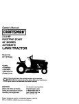
Owner's Manual
ICRAFTSMAH°I
16.0 HP
ELECTRIC START
42" MOWER
AUTOMATIC
LAWN TRACTOR
Model No.
917.272063
•
•
•
•
Safety
Assembly
Operation
Maintenance
• Repair Parts
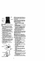
CAUTION:
Read and follow all Safety
Rules and Instructions before
operating this equipment.
For answers toyour questions
about this product, Call:
1-800-659-5917
Sears Craftsman Help Line
5 am - 5 pm, Mon - Sat
Sears, Roebuck and Co., Hoffman Estates, II 60179
Visit our Craftsman website:www.sears.com/craftsman
Warranty
...............................................
Maintenance Schedule ...................... 18
Service and Adjustments .................... 23
Storage ............................................... 29
Troubleshooting ................................. 30
Repair Parts ........................................ 34
Parts Ordedng ..................... Back Cover
2
Safety Rules ......................................... 3
Product Specifications .......................... 6
Assembly .............................................. 8
Operation ............................................ 11
Maintenance ....................................... 18
LIMITED'I3NO YEAR WARRANTY ON CRAFTSMAN RIDING EQUIPMENT PARTS
For two (2) years from the date of purchase, ff this Craftsman Riding Equipment is
maintained, lubricated end tuned up according to the instructions in the owner's
manual, Sears will repair or replace, free of charge, any parts found to be defective in
matedsl or workmanship. Warranty service is available free of charge by returning
your Craftsman riding equipment to your nearest Sears Service Center. In-home
warranty service is available but a trip charge will apply. This warranty applies only
while this product is in the United States.
This Warranty does not cover:
• Expendable items which become worn dudng normal use, such as blades, spark
plugs, air cleaners, belts and oil filters,
• Tire replacement or repair caused by punctures from outside objects, such as nails,
thorns, stumps, or glass.
• Repairs necessary because of operator abuse, including but not limited to, damage
caused by towing objects beyond the capability of the dding equipment, impacting
objects that bend the frame or crankshaft, or over speeding the engine.
• Repairs necessary because of operator negligence, including but not limited to,
electrical and mechanical damage caused by improper storage, failure to use the
proper grade and amount of engine oil, failure to keep the deck clear of flammable
debris, or the failure to maintain the equipment according to the instructions
contained in the owner's manual.
• Engine (fuel system) cleaning or repairs caused by fuel determined to be contaminated or oxidized (stale) In general, fuel should be used within thirty (30) days of its
purchase date.
• Riding equipment used for commercial or rental purposes. A product is "used for
commercial purpose" it is used for any purpose other than single family household
dwellings or in usage where profit is made.
LIMITED 90 DAY WARRANTY ON BA'I-rERY
For ninety (90) days from date of purchase, it any battery included with this dding
equipment provas defective in matedal or workmanship and our testing determines
the battery will not hold a charge, Sears will replace the battery at no charge. Warranty
service is available free of charge by returning your Craftsman dding equipment to
your nearest Sears Service Center. In-home warranty service Is available but a trip
charge will apply. This warranty applies only while this product is in the United States.
TO LOCATE THE NEAREST SEARS SERVICE CENTER ORTO SCHEDULE INHOME WARRANTY SERVICE, SIMPLY CONTACT SEARS AT 1-800-4-MY-HOME
This Warranty gives you specific legal dghts, and you may also have other dghts
which may vary from state to state.
Sears, Roebuck and Co., D/817 WA, Hoffman Estates, IL 60179
2
IMPORTANT: This cuffing machine is capable of amputating hands and feet and
throwing objects. Failure to observe the following safety instructions could result in
serious injury or death.
Clean any oil or fuel spillage before
I. GENERAL OPERATION
operating or stodng the machine. Allow
• Read, understand, and follow all
machine to cool before storage.
instructionsin the manual and on the
I1.
SLOPE OPERATION
machine before starting.
• Only allow responsible adults, who are
Slopes are a major factor related to lossfamiliar with the instructions, to operate
of-control and itpover accidents, which
the machine.
can result In severe injury or death. All
• Clear the area of objects such as
slopes require extra caution. If you
rocks, toys, wire, etc., which could be
cannot back up the slope or if you feel
picked up and thrown by the blade.
uneasy on it, do not mow it.
• Be sure the area is clear of other
DO:
people before mowing. Stop machine
• Mow up and down slopes, not across.
if anyone enters the area.
• Remove obstacles such as rocks, tree
• Never carry passengers.
limbs, etc.
• Do not mow in reverse unless absoWatch for holes, ruts, or bumps.
lutely necessary. Always look down
Uneven terrain could overturn the
and behind before and while backing.
machine. Tall grass can hide obstacles.
• Be aware of the mower discharge
Use slow speed. Choose a low gear
direction and do not point it at anyone.
so that you will not have to stop or shift
Do not operate the mower without
while on the slope.
either the entire grass catcher or the
Follow the manufacturer's recommenguard in place.
dations for wheel weights or counter• Slow down before turning.
weights to improve stability,
• Never leave a running machine
Use extra care with grass catchers or
unattended. Always turn off blades, set
other attachments. These can change
parking brake, stop engine, and
the stabilifyof themachine.
remove keys before dismounting.
Keep all movement on the slopes slow
• Turn off blades when not mowing.
and gradual. Do not make sudden
• Stop engine before removing grass
changes in speed or direction.
catcher or unclogging chute.
Avoid starting or stopping on a slope. If
• Mow only in daylight or good artificial
tires lose traction, disengage the
light.
blades and proceed slowly straight
• Do not operate the machine while
down the slope.
under the influence of alcohol or drugs.
DO NOT:
• Watch for traffic when operating near or
• Do net turn on slopes unless necescrossing roadways.
sary, and then, turn slowly and gradu• Use extra care when loading or
ally downhill, if possible.
unloading the machine into a trailer or
• Do not mow near drop-offs, ditches, or
truck.
embankments. The mower could
• Data Indicates that operators, age 60
suddenly turn over if a wheel is over
years and above, are involved in a
the edge of a cliff or ditch, or if an edge
large percentage of riding mowercaves in.
related injudes. These operators
• Do not mow on wet grass. Reduced
should evaluate their ability to operate
traction could cause sliding.
the dding mower safely enough to
• Do not try to stabilize the machine by
protect themselves and ethers from
putting your foot on the ground.
sedous injury.
• Do not use grass catcher on steep
• Keep machine free of grass, leaves or
slopes.
other debds build-up which can touch
hot exhaust / engine parts and bum.
Do not allow the mower deck to plow
leaves or other debds which can cause
build-up to occur.
3
Ill. CHILDREN
• Never run a machine inside a closed
Tragic accidents can occur if the operator
area.
is not alert to the presence of children.
• Keep nuts and bolts, especially blade
Children are often attracted to the
attachment belts, tight and keep
machine and the mowing activity. Never
equipment in good condition.
assume that children will remain where
• Never tamper with safety devices.
you last saw them.
Check their proper operation regulady.
• Keep children out of the mowing area
• Keep machine free of grass, leaves, or
and under the watchful care of another
other debds build-up. Clean oil or fuel
respens_le adult.
spillage. Allow machine to cool before
• Be alert and turn machine off if children
stodng.
enter the area.
• Stop and inspect the s_:tuipmentif you
• Before and when backing, look behind
strike an object. Repair, if necessary,
and down for small children.
before restarting.
• Never carry chiidren. They may fall off
• Never make adjustments or repairs
and be seriously injured or interfere
with the engine running.
with safe machine operation,
• Grass catcher components are subject
• Never allow children to operate the
to wear, damage, and deterioration,
machine.
which could expose moving parts or
• Use extra care when approaching blind
allow objects to be thrown. Frequently
corners, shrubs, trees, or other objects
check components and replace with
manufacturer's recommended pads,
that may obscure vision.
when necessary.
IV, SERVICE
• Mower blades are sharp and can cut.
• Use extra care in handting gasoline
Wrap the blede(s) or wear gloves, and
and other fuels. They are flammable
use extra caution when servicing them,
and vapors are explosive.
• Check brake operation frequently.
- Use only an approved container.
Adjust and service as required.
- Never remove gas cap or add fuel
with the engine running. Allow
engine to cool before refueling. Do
not smoke.
- Never refuel the machine indoors.
- Never store the machine or fuel
container inside where there is an
open flame, such as a water heater.
@@@@@
* Be sure the area is clear of other
people before mowing. Stop machine if
anyone enters the area.
• Never carry passengers or children
even with the blades off.
• Do not mow in reverse unless absolutely necessary. Always look down
and behind before and while backing.
• Never carry children. They may fall off
and be seriously injured or interfere
with safe machine operation.
Keep children out of the mowing area
and under the watchful care of another
responsible adult.
4
• Be alert and turn machine off if children
enter the area.
• Before and when backing, look behind
and down for small children.
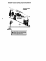
• Mow up and down slopes (15° Max),
not across.
• Remove obstacles such as rocks, tree
limbs, etc.
• Watch for holes, ruts, or bumps.
Uneven terrain could overturn the
machine. Tall grass can hide obstacles,
• Use slow speed. Choose a low gear so
that you will not have to stop or shift
while on the slope.
• Avoid startingor stopping on a slope, it
tires lose traction, disengage the
blades and procesd slowly straight
down the slope.
• If machine stops while going uphill,
disengage blades, shift into reverse
and back down slowly.
• Do not turn on slopes unless necessary, and then, turn slowly and gradually downhill, if possible.
A_k CAUTION: Tow only the attachments
that are recommended by and comply
with specifications of the manufacturer of
your tractor. Use common sense when
towing. Operate only at the lowest
possible speed when on a slope. Too
heavy of a load, while on a slope, is
dangerous. Tiros can lose traction with
the ground and cause you to lose control
of your tractor.
A_kWARNING: Engine exhaust, some of
its constituents, and certain vehicle
components contain or emit chemicals
known to the State of California to cause
cancer and birth defects or other repro.
ductive harm.
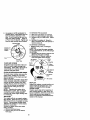
_bLook for this symbol to point out
important safety precautions. It means
CAUTIONIII BECOME ALERTnl YOUR
SAFETY IS INVOLVED.
_WARNING:
Battery posts, terminals
and related accessories contain lead and
lead compounds, chemicals known to the
State of California to cause cancer and
birth defects or other reproductive harm.
Wash hands after handling.
,_ CAUTION: In order to prevent
accidental starting when setting up,
transpor'dng,adjusting or making repairs,
always disconnect spark plug wire and
place wire where k cannot contact spark
plug.
CAUTION: Do not coast down a hill
in neutral, you may lose control of the
tractor.
5
PRODUCT
SPECIFICATIONS
GASOLINE
CAPACITY
AND TYPE:
1.25 GALLONS
UNLEADED
REGULAR
OiLTYPE
API-SF-SJ):
OIL CAPACITY:
SAE 1OW30(above32°F)
SAE 5W-30 (below32°F)
W/FILTER: 4.0 PINTS
W/OFILTER: 3.5 PINTS
CHAMPION RC12YC
SPARK PLUG:
GAP: .040")
GROUND
SPEED(MPH):
TIRE
CHARGING
SYSTEM:
BAI-r ERY:
BLADE BOLT
TORQUE:
REPAIR AGREEMENT
A Repair Agreement is available on this
product. Contact your nearest Sears
store for details.
CUSTOMER RESPONSIBILITIES
• Read and observe the safety rules.
• Follow a regular schedule in maintain.
ing, cadng for and using your tractor.
• Follow the instructions under =Maintenance" and "Storage" sections of this
owner's manual.
_WARNING:
This tractor is equipped
with an intemal combustion engine and
should not be used on or near any
unimproved forest-covered, brashcovered or grass-covered land unless the
engine's exhaust system is equipped with
a spark arrester meeting applicable local
or state laws (if any). If a spark arrester is
used, it should be maintained in effective
working order by the operator.
In the state of Califomia the above is
required by law (Section 4442 of the
Calitomia Public Resources Code).
Other states may have similar laws.
Federal laws apply on federal lands. A
spark arrester for the muffler is available
throughyour nearest Sears service
center (See REPAIR PARTS section of
this manual).
FORWARD: 5.5
REVERSE: 2.4
FRONT:
14 PSI
REAR:
10 PSI
15 AMPS @ 3600 RPM
AM P/HR:
30
MIN. CCA: 240
CASE SIZE: U1 R
27-35 FT. LBS.
CONGRATULATIONS on your purchase
of a new tractor, It has been designed,
engineered and manufactured to give
you the best possible dependability and
performance.
Should you experience any problem you
cannot easily remedy, please contact a
Sears or other qualified service center.
We have competent, wall-trained techniclans and the proper tools to service or
repairthis tractor.
Please read and retain this manual. The
instructions will enable you to assemble
and maintain your tractor properly.
Always observe the =SAFETY RULES'.
6
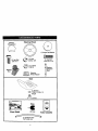
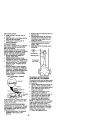
Steering
Wheel Insert
Steering Wheel
C)
(1) Large Flat Washer
(1) Hex Bolt
5/16-t8 x 1-1/4
(1) Lock 3/8
washer
(1)
3/8-16
Hex x
Bolt
1
(1) Locknut
5/16-18
Steedng
Extension
Shaf_
Steering
Boot
_L
Steering
Wheel Adapter
Seat
(_)(1)
Washer
17/32 x 1-3/16 x 12
Keys
Slope Sheet
(2)Keys
(1) Oil Drain Tube
For Future Use
7
Video Cassette
Your new tractor has been assembled at the factory with exception of those parts left
unassembled for shipping purposes. To ensure safe and proper operation of your
tractor all parts and hardware you assemble must be tightened securely. Use the
correct tools as necessary to insure proper tightness. Review the video cassette before
you begin.
TOOLS REQUIRED FOR ASSEMBLY
A socket wrench set will make assembly
easier. Standard wrench sizes you need
are nsted below.
(1) 9/16' wrench
(2) 1/2" wrench
(1) Tire pressure
(1) Utilityknife
gauge
When dght or left hand is mentioned in
this manual, it means, from your point of
view, when you are in the operating
position (seated behind the steering
wheel).
TO REMOVETRACTOR
FROM
CARTON
UNPACK CARTON
1. Remove all accessible loose parts
and parts cartons from carton.
2. Cut, from top to bottom, along lines on
all four comers of carton, and lay
panels flat.
3. Check for any additional loose parts
or cartons and remove.
BEFORE REMOVINGTRACTOR
FROM SKID
ATrACH STEERING WHEEL
6. Assemble large flat washer, 3/8 lock
washer, 3/8 hex bolt and lighten
securely.
7. Snap steering wheel insert into center
of steering wheel.
8. Remove protective materials from
tractor hood and gdll.
IMPORTANT: Check for and remove any
staples in skid that may puncture tire
where tractor is to roll off skid.
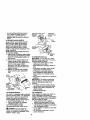
ASSEMBLE EXTENSION SHAFT AND
BOOT
1. Slide extension shaft onto lower
steedng shaft. Align mounting holes
in extension and lower shafts and
install 5/16 hex bolt and Iocknut.
Tighten securely.
IMPORTANT: Tighten bolt and nut
securely to 18-22 ft. Ibs torque.
2. Place tabs of steedng boot over tab
slots in dash and push down to
secure.
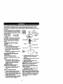
iNSTALL STEERING WHEEL
3. Positionfront wheels of the tractor so
they are pointing straight forward.
4. Remove steering wheel adapter from
steering wheel and slide adapter onto
steedng shaft extension.
5. Position steedng wheel so cross bars
are horizontal (left to dght) and slide
inside boot and onto adapter.
HOWTO SET UPYOURTRACTOR
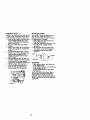
CHECK BATFERY
1. Lift seat pan to raised position and
open battery box door.
NOTE: If this battery is put into service
after month and year indicated on label
(label located between terminals) charge
battery for minimum of one hour at 6-10
amps. (See "BA'I-I'ERY" in Maintenance
section of this manual for charging
instructions).
8
Label
Batter
Door
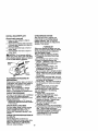
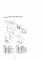
INSTALL SEAT
Adjust seat before tightening adjustment
knob.
1. Remove adjustment knob end flat
washer secudng seat to cardboard
packing and set aside for assembly of
seat to tractor.
2. Pivot seat upward and remove from
the cardboard packing. Remove the
cardboard packing and discard.
3. Place seat on seat pan so head of
shoulder belt is positioned over large
slotted hole in pan.
4. Push down on seat to engage
shoulder bolt in slot and pull seat
towards rear of tractor.
5. Pivot seat and pan forward and
assemble adjustment knob end flat
washer loosely. Do not tighten.
6. Lower seat into operating position and
sit in seat.
7. Slide seat until a comfortable position
is reached which allows you to press
clutch/brake pedal all the way down.
8. Get off seat without moving its
adjusted position.
9. Raise seat and tighten adjustment
knob securely.
NOTE: You may now roll or drive your
tractor off the skid. Follow the appropriate
instruction below to remove the tractor
from the skid.
TO ROLLTRACTOR
OFF SKID (See
Operation section for location and
function of controls)
1. Press lift lever plunger and raise
attachment lift lever to its highest
position.
2. Release parking brake by depressing
clutch/brake pedal.
3, Place freewheel control in freewheeling position to disengage transmission (See =TO TRANSPORT" in the
Operation section of this manual).
4. Roll tractor forward off skid.
5. Remove banding holding deflector
shield up against tractor.
TO DRIVETRACTOR
OFF SKID (See
Operation section for location and
function of controls)
WARNING: Before starting, read
understand and follow a instructons n
the Operation section of this manual. Be
sure tractor is in a well-ventilated area. Be
sure the area in front of tractor is clear of
other people and objects.
1. Be sure all the ebove assembly steps
have been completed.
2. Check engine oil level and fill fuel
tank with gasoline.
3. Place freewheel control in "transmission engaged" position.
4. Sit on seat in operating position,
depress clutch/brake pedal and set
the parking brake.
5. Place motion control lever in neutral
(N) position.
6. Press lift lever plunger end raise
attachment lift lever to its highest
position.
7. Start the engine. After engine has
started, move throttle control to idle
position.
8. Release parking brake.
9. Slowly move the motion control lever
forward and slowly drive tractor off
skid.
10.Apply brake to stop tractor, set parking
brake and place motion control lever
in neutral position.
11.Tum ignition key to "OFF" position.
Continue with the instructionsthat follow.
Seat
ShOulder
Bolt
9
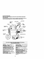
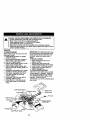
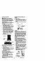
INSTALL
MULCHER
PLATE
(If previously removed)
1. Raise and hold deflector shield in
upright position.
2. Place front of mulcher plate over front
of mower deck opening and slide into
place, as shown.
3. Hook front latch into hole on front of
mower deck.
4. Hook rear latch into hole on back of
mower deck.
_CAUTION:
Do not remove deflector
shield from mower. Raise and hold shield
when attaching mulcher plate and allow it
to rest on plate while in operation.
Mulcher
Plate
Shield
.arch
Hooks
TO CONVERTTO
DISCHARGING
BAGGING
OR
Simply remove mulaher plate and store in
a safe place. Your mower is now ready for
discharging or installation of optional
grass catcher accessory.
NOTE: It is not necessary to change
blades, The mulcher blades are designed for discharging and bagging also.
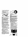
CHECKTIRE
PRESSURE
The tires on your tractor were overinflated
at the factory for shipping puq)oses.
Correct tire pressure is important for best
cutting performance.
• Reduce tire pressure to PSI shown in
"PRODUCT SPECIFICATIONS" section
of this manual.
CHECK DECK LEVELNESS
For best cutting results, mower housing
should be properly leveled. See =TO
LEVEL MOWER HOUSING" in the
Service and Adjustments section of this
manual.
CHECK BRAKE SYSTEM
After you learn how to operate your
tractor, check to see that the brake is
propedy adjusted. See TO ADJUST
BRAKE" in the Service and Adjustments
section of this manual.
V'CHECKLIST
Before you operate and enjoy your new
tractor, we wish to assure that you receive
the best performance and satisfaction
from this Quality Product.
Please review the following checklist:
,/'All assembly instructions have been
completed.
.,/No remaining loose parts in carton.
V"Battery is properly prepared end
charged. (Minimum 1 hour at 6 amps).
.,/-Seat is adjusted comfortably and
tightened securely.
,/'All tiros are properly inflated. (For
shipping purposes, the tiros were
ovednflated at the factory).
,/Be sure mower deck is propedy leveled
slde-to-slde/front-to-raar for best cutting
results. (Tires must be propady inflated
for leveling).
./-Check mower and ddve belts. Be sure
they are routed properly around pulleys
and inside all belt keepers.
./Check widng. See that all connections
are still secure and wires are propedy
clamped.
V"Before ddving tractor, be sure freewheel control is in drive position.
While learning how to use your tractor,
pay extra attention to the following
important items:
V" Engine oil is at proper level.
v"Fuel tank is filled with fresh, clean,
regular unleaded gasoline.
./Become familiar with all controls - their
location and function. Operate them
before you start the engine.
v"Be sure brake system is in safe
operating condition.
V It is important to purge the transmission
before operating your tractor for the first
time. Follow proper starting and
transmission purging instructions (See
=TO START ENGINE" and "PURGE
TRANSMISSION" in the Operation
section of this manual).
CHECK FOR PROPER POSITION OF
ALL BELTS
See the figures that are shown for
replacing motion and mower blade drive
belts in the Service and Adjustments
section of this manual. Verify that the
belts are routed correctly,
10
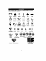
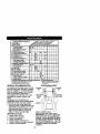
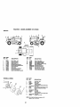
These
symbols
mayappear
onyourtractor
orin literature
supplied with the product.
Learn and understand their meaning.
BATTERY
CAUTION OR
WARNING
REVERSE
ENGINE ON
ENGINE OFF
OIL PRESSURE
LIGHTS ON
OVER TEMP
LIGHT
FUEL
CHOKE
MOWER HEIGHT
PARKING BRAKE
LOCKED
UNLOCKED
A'i'rACHM ENT
CLUTCH ENGAGED
_)
REVERSE
NEUTRAL
ATTACHMENT
IGNITION
FORWARD
FAST
H
L
HIGH
LOW
KEEP AREA CLEAR
CLUTCH DISENGAGED
SLOW
t
!
MOWER LIFT
PARKING BRAKE
SLOPE HAZARDS
(SEE SAFETY RULES SECTION)
FREE WHEEL
(Automatic Modelsonly)
DANGER, KEEP HANDS AND FEET AWAY
11
KNOWYOURTRACTOR
READ THIS OWNER'S MANUAL AND SAFETY RULES BEFORE OPERATING
YOUR TRACTOR
Compare the illustrationswith your tractor to famiUadze yourself with the locations of
various controls and adjustments, Save this manual for future reference,
Light Switch
Attachment
Clutch
Ammeter
Ignition Switch
......
.
/
Lift
Lever
Plunger
Throttle/Choke
Control
Attachment
LiftLever
Clutch/Brake
Pedal
Height
Adjustment
Indicator
Freewheel
Control
Parking Brake Lever
Motion Control
Lever
Our tractors conform to the safety standards of the American
National Standards Institute.
AMMETER - Indicates charging (+) or
discharging (-) of battery.
ATTACHMENT CLUTCH LEVER - Used
to engage the mower blades, or other
attachments mounted to your tractor,
ATTACHMENT LIFT LEVER - Used to
raise, lower, and adjust the mower deck
or other attachments mounted to your
tractor.
CLUTCWBRAKE PEDAL - Used for
declutching and braking the tractor and
starting the engine.
MOTION CONTROL LEVER - Selects the
speed and direction of tractor.
IGNmON SWITCH - Used for starting and
stopping the engine.
LIFT LEVER PLUNGER - Used to release
attachment lift lever when changing its
position.
LIGHT SWITCH - Turns the headlights on
and off.
PARKING BRAKE LEVER - Locks clutch/
brake pedal into the brake position.
THRO'I'FLE/CHOKE CONTROL - Used
for starting and controllingengine speed.
FREEWHEEL CONTROL Disengagages transmission for pushing
or slowlytowing the tractor with the
engine off.
12
The operation of any tractor can result in foreign objects thrown into the
eyes, which can result in severe eye damage. Always wear safety
glasses or eye shields while operating your tractor or performing any
adjustments or repairs. We recommend a wide vision safety mask over
spectacles or standard safety glasses.
HOWTO USEYOURTRACTOR
TO SET PARKING BRAKE
Your tractor is equipped with an operator
presence sensing switch. When engine
is running, any attempt by the operator to
leave the seat withoutfirst setting the
parking brake will shut off the engine.
1. Depress clutch/brake pedal into full
"BRAKE" position and hold.
2. Place parking brake laver in =ENGAGEDI position end release
pressure from clutch/brake pedal.
Pedal should remain in =BRAKE"
position. Make sure parking brake will
hold tractor secure.
Throttle/
AttachmentClutch Lever
Choke \
_
"Engaged"
_/Ignition
_'_ ,_:_
,,\\
r
Key
"Disengaged"
BrakePedal"_-,_'=_'_'_-_Y--:V
"Engaged"
Position
STOPPING
• Never use choke to stop engine.
IMPORTANT: Leaving the ignition switch
in any position other than "OFF" will
cause the battery to be discharged,
(dead).
NOTE: Under certain conditions when
tractor is standing idle with the engine
running, hot engine exhaust gases may
cause "browning"of grass. To eliminate
this possibility,always stop engine when
stopping tractor on grass areas.
_ILCAUTION: A ways _op tractor completely, as descdbei:l above, berore
leaving the operator's position; to empty
grass catcher, etc.
TO USE THRO'n'LE CONTROL
Always operate engine at full throttle.
• Operating engine at less than full
throttle reduces the battery charging
rate.
• Full throttle offers the best bagging and
mower performance.
TO MOVE FORWARD AND
BACKWARD
The direction and speed of movement is
controlled by the moron control lever.
1. Start tractor with motion control lever
in neutral (N) position.
2. Release parking brake.
3. Slowly move motion control lever to
desired position.
TO ADJUST MOWER CUTTING HEIGHT
MOWER BLADES • To stop mower blades,move attachment clutch lever to =DISENGAGED"
position.
The position of the attachment I_ lever
GROUND DRIVE.
determines the cutting height.
• Grasp lift lever.
• To stop ground drive, depress clutch/
• Press plunger with thumb and move
brake pedal into full "BRAKE" position.
lever to desired position.
• Move motion control lever to neutral (N)
The cutting height range is approxiposition.
IMPORTANT: The motion control lever
mately 1-1/2 to 4". The heights are
does not return to neutral (N) position
measured from the ground to the blade
when the clutch/brake pedal is detip with the engine not running. These
pressed.
heights are approximate and may vary
depending upon soil conditions, height of
ENGINE grass and types of grass being mowed.
• Move throttle control to slow position.
• The average lawn should be cut to
NOTE: Falure to move throttle control to
approximately 2-1/2 inches during the
slow position and allowing engine to idle
cool season and to over 3 inches
before stopping may cause engine to
dudng hot months. For healthier and
"backfire'.
better looking lawns, mow often and
• Turn ignition key to =OFP position and
after moderate growth.
remove key. Always remove key when
leaving tractor to prevent unauthodzed
use.
13
• For best cutting performance, grass
over 6 inches in height should be
mowed twice. Make the first cut
relatively high; the second to desired
height.
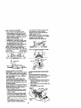
TO ADJUST GAUGE WHEELS
Gauge wheels are properly adjusted
when they are slightly off the ground
when mower is at the desired cutting
height in operating position. Gauge
wheels then keep the deck in proper
position to help prevent scalping in most
terrain conditions.
NOTE: Adjust gauge wheels with tractor
on a flat level surface.
1. Adjust mower to desired cutting height
(See "TO ADJUST MOWER CU'I-I'ING
HEIGH'r' in the Operation section of
this manual).
2. With mower in desired height of cut
position, gauge wheels should be
assembled so they are slightly off the
ground. Install gauge wheel in
appropriate hole with shoulder bolt,
3/8 washer, and 3/8-16 Icoknut and
tighten securely.
3. Repeat for opposite side installing
gauge wheel in same adjustment
hole.
3/8-16
Locknut
Wheel
Mounting
Shoulder
Gaug*
TO OPERATE MOWER
Your tractor is equipped with an operator
presence sensing switch. Any attempt by
the operator to leave the seat with the
engine running and the attachment
clutch engaged will shut off the engine.
1. Select desired height of cut.
2. Start mower blades by engaging
attachment clutch control.
TO STOP MOWER BLADES disengage attachment clutch control.
_, CAUTION: Do not operate the
mower without either the en#re grass
catcher, on mowers so equipped, or the
deflector shield in place.
AttachmentClutchLever
=pEnosgi#aogned*
_
Attachemnt
/
LpiflosLitieVner
High
_
_/
I_si_ion
"X_
Deflector
SNeld
TO OPERATE ON HILLS
_I,CAUTION: Do not drive up or down
hills with slopes greater than 15° and do
not ddve across any slope.
• Choose the slowest speed before
starting up or down hills.
• Avoid stopping or changing speed on
hills.
• If slowing is necessary, move throttle
control lever to slower position.
• If stopping is absolutely necessary,
push clutch/Drake pedal quickly to
brake position and engage parking
brake.
• Move motion control lever to neutral (N)
position.
IMPORTANT: The motion control lever
does not return to neutral (N) position
when the clutch/'orake pedal is depressed.
• To restart movement, slowly release
parking brake and clutch/brake pedal.
• Slowly move motion control lever to
slowest setting.
• Make all rums slowly.
TO TRANSPORT
When pushing or towing your tractor, be
sure to disengage transmission by
placing freewheel control in freewheeling
position. Free wheel control is located at
the rear drawbar of tractor.
1. Raise attachment lift to highest
position with attachment lift control.
2. Pull freewheel control out and down
into the slot and release so it is held in
the disengaged position.
• Do not push or tow tractor at more than
two (2) MPH.
• To reengage transmission, reverse
above procedure.
14
NOTE: To protect hood from damage
when transporting your tractor on a truck
or a trailer, be sure hood is closed and
secured to tractor. Use an appropriate
means of tying hood to tractor (rope, cord,
etc.).
TOWING CARTS AND OTHER ATtACHMENTS
Tow only the attachments that are
recommended by and comply with
specifications of the manufacturer of your
tractor. Use common sense when towing.
Too heavy of a load, while on a slope, is
dangerous. Tires can lose traction with
the ground and cause you to lose control
of your tractor.
BEFORE STARTINGTHE ENGINE
CHECK ENGINE OIL LEVEL
The engine in your tractor has been
shipped, from the factory, already filled
with summer weight oil.
1. Check engine oil with tractor on level
ground.
2. Unthread and remove oil fill cap/
dipstick; wipe oil off. Reinssrt the
dipstickinto the tube and rest oil fill
cap on the tube. Do not thread the
cap onto the tube. Remove and read
oil level, if necessary, add oil until
=FULL" mark on dipstickis reached.
Do not ovedill.
* For cold weather operationyou should
change oil for easier starting (See "OIL
VISCOSITY CHART" in the Maintenance section of this manual).
• To change engine oil, see the Maintenance section in this manual.
ADD GASOLINE
• Fill fuel tank. Use fresh, clean, regular
unleaded gasoline With a minimum of
87 octane. (Use of leaded gasoline
will increase carbon and lead oxide
deposits and reduce valve life). Do not
mix oil with gasoline. Purchase fuel in
quantities that can be used within 30
days to assure fuel freshness.
IMPORTANT: When operating in
temperatures below 32°F(0°C), use fresh,
clean winter grade gasoline to help
insure good cold weather starting.
AWARNING:
Experience indicates that
alcohol blended fuels (called gasohol or
using ethanol or methanol) can attract
moisture which leads to separation and
formation of acids during storage. Acidic
gas can damage the fuel system of an
engine while in storage. To avoid engine
problems, the fuel system should be
emptied before storage of 30 days or
longer. Drainthe gastank, start the
engine and let it run until the fuel lines
and carburetor are empty. Use fresh fuel
next season. Sea Storage Instructionsfor
additional information. Never use engine
or carburetor cleaner products in the fuel
tank or permanent damage may occur.
_,CAUTION:
Fill to bottom of gastank
filler neck. Do not overfill. Wipe off any
spilled oil or fuel. Do not store, spillor
use gasoline near an open flame.
TO START ENGINE
When starting the engine for the first time
or if the engine has run out of fuel, it will
take extra cranking time to move fuel from
the tank to the engine.
1. Be sure freewheel control is in the
transmission engaged position.
2. Sit on seat in operating position,
depress clutch/brake pedal and set
parking brake.
3. Place motion control lever in neutral
(N) position.
4. Move attachment clutch to =DiSENGAGED" position.
5. Move throttle control to choke position.
NOTE: Before starting, read the warm
and cold starting procedures below.
6. Insert key Into ignition and rum key
clockwise to =START" position and
release key as soon as engine starts.
Do not run starter continuouslyfor
more than fifteen seconds per minute.
If the engine does not start alter
several attempts, move throttle control
to fast position, wait a few minutes and
try again, if engine still does not start,
move the throttle control back to the
choke position and retry.
15
WARM WEATHER STARTING (50° F end
above)
7. When engine starts, move the throttle
control to the fast position.
The attachments and ground drive
can now be used. If the engine does
not accept the load, restart the engine
and allow it to warm up for one minute
using the choke as described above.
COLD WEATHER STARTING ( 50° F and
below)
8. When engine starts, allow engine to
run with the throttle control in the
choke position until the engine runs
roughly,then move throttle control to
fact position.This may require an
engine warm-up period from several
seconds to several minutes, depending on the temperature.
AUTOMATIOTRANSMISSION WARM UP
Before driving the unit in cold weather,
the transmission should be warmed up as
follows:
1. Be sure the tractor is on level ground.
2. Place the motion control lever in
neutral, Release the parking brake
and let the clutch/brake slowly return
to operating position.
3. Allow one minute for transmission to
warm up. This can be done during
the engine warm up period.
• The attachments can also be used
during the engine warm-up pedod after
the transmission has been warmed up.
NOTE: If at a high altitude (above 3000
feet) or in cold temperatures (below 32 F)
the carburetor fuel mixture may need to
be adjusted for best engine performance.
See "TO ADJUST CARBURETOR" in the
Service and Adjustments section of this
manual.
PURGETRANSMISSION
_QI,
CAUTION: Never engage or disengage freewheel lever while the engine is
running.
To ensure proper operation and performance, it is recommended that the
transmission be purged before operating
tractor for the first time. This procedure will
remove any trapped air inside the
transmission which may have developed
dudng shipping of your tractor.
IMPORTANT: Should your transmission
require removal for service or replacement, it should be purged after reinstallation before operating the tractor.
1. Place tractor safely on level surface
with engine off and parking brake set.
2. Disengage transmission by placing
freewheel control in freewheeling
position (See "TO TRANSPORT" in
this sect=onof manual).
3. Sitting in the tractor seat, start engine.
After the engine is running, move
throttle control to slow position. With
motion control lever in neutral (N)
position, slowly disengage clutch/
brake pedal.
4. Move motion control lever to full
forward position and hold for five (5)
seconds. Move lever to full reverse
position and hold for five (5) seconds.
Repeat this procedure three (3) times.
NOTE: During this procedure there will be
no movement of drive wheels. The air is
being removed from hydraulicdrive
syctem.
5. Move motion control lever to neutral
(N) position. Shut- off engine and set
parking brake.
6. Engage transmission by placing
freewheel control in driving position
(See "TO TRANSPORT" in this section
of manual).
7. Sitting in the tractor seat, start engine.
After the engine Is running, move
throttle control to haft (1/2) speed. With
motion control lever in neutral (N)
position, slowly disengage clutch]
brake pedal.
8. Slowly move motion control lever
forward, after the tractor moves
approximately five (5) feet, slowly
move motion control lever to reverse
position. After the tractor moves
approximately five (5) feet ratum the
motion control lever to the neutral (N)
position. Repeat this procedure with
the motion control lever three (3)
times.
Yourtractor is now purged and now ready
for normal operation.
16
MOWINGTIPS
• Mower should be pmpedy leveled for
best mowing performance. See =TO
LEVEL MOWER HOUSING" in the
Service and Adjustments section of this
manual.
• The left hand side of mower should be
used for trimming.
• Drive so that clippings are discharged
onto the area that has been cut. Have
the cut area to the right of the tractor.
This will result in e more even distribution of clippings and more uniform
cutting.
• When mowing large areas, start by
turning to the dght so that clippings will
discharge away from shrubs, fences,
driveways, etc. After one ortwo
munds, mow In the opposite direction
making left hand turns untDfinished.
• If grass Is extremely tall, it should be
mowed twice to reduce load and
possible fire hazard from dried clippings. Make first cut relatively high; the
second to the desired height.
• Do not mow grass when if is wet. Wet
grass will plug mower and leave
undesirable clumps. Allow grass to dry
before mowing.
• Always operate engine at full throttle
when mowing to assure better mowing
performance and pmpor discharge of
material. Regulate ground speed by
selecting a low enough gear to give the
mower cutting performance as well as
the quality of cut desired.
• When operating attachments, select a
ground speed that will suit the terrain
and give best performance of the
attachment being used.
MULCHING MOWINGTIPS
IMPORTANT: For best performance,
keep mower housing free of built-up
grass and trash. Clean after each use.
• The special mulching blade will recut
the grass clippings many times and
reduce them in size so that as they fall
onto the lawn they will disperse into the
grass end not be noticed. Also, the
mulched grass will biodegrede quickly
to provide nutdants for the lawn.
Always mulch with your highest engine
(blade) speed as this will provide the
best recurring action of the blades.
• Avoid cutting your lawn when it is wet.
Wet grass tends to form clumps and
interferes with the mulching action.
The best time to mow your lawn is the
early aftemoon. At this time the grass
has dried and the newly cut area will
not be exposed to the direct sun.
• For best results, adjust the mower
cutting height so that the mower cuts off
only the top one.third of the grass
blades. For extremely heavy mulching,
reduce your width of cut on each pass
and mow slowly.
• Certain types of grass and grass
conditions may require that an area be
mulched a second time to completely
hide the clippings. When doing a
second cut, mow across or perpendicular to the first cut path,
• Change your cutting pattern from week
to week. Mow north to south one week
then change to east to west the next
week. This will help prevent matting
and graining of the lawn.
17
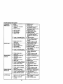
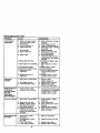
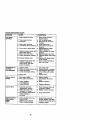
MAINTENANCESCHEDULE
FILL IN DATES
AS YOU COMPLETE
REGULAR SERVICE
ERVICE DA*IIES
_eck BrakJOpemdon
Ch_k
li/
I*/
Tim Pre_su_
Check Opemtor presence and
C;lack for Loose Fa_fa_em
S_a_eplac*
_
J,
I1_
Lubrk_on Chart
CheckBaltor_Lm_)
Clean IBa_ry _d
I/
Tirmlnals
,/
Check Tra_t_x_e Cool_
v',
/,
AdJ,JstBtado Bait(s) T_sk_
Ad_ Moron Driw _s)
Ch_k
v'
v',
v'
V,
Blades
Tms_n
Engl.e Oil Letel
I_
v'
ChangeEng_eOil
Clean Air Filter
Claan Ak Screen
v',
i/,
!v'
Inspe_ Muffler/Spark _r
F_p_== _1 Fllm¢(h"equlpp_l)
¢_sanEn_s Cao_ Fins
ReplaceSperkPlug
Rep_
I/,
Air Filter Paper Cartridge
v'
Replaca Fuel Filter
el.Notn_ulr_mle_lpp_r_ ,,_lh_,_*let
ee_-'_
GENERAL RECOMMENDATIONS
The warranty on this tractordoes not cover
items that have bean subjected to operator
abuse or negligence. To receive full value
from the warranty,operator must maintain
tractoras instructedin this manual.
Some adjustments will need to be made
periodically to properly maintain your
tractor.
All adjustments in the Service and
Adjustmentssection of this manual should
be checked at least once each season.
• Once a year you should replace the
spark plug, clean or rePlace air filter, and
check blades and belts for wear, A new
spark plug and clean air filter assure
proper air-fuel mixture and help your
engine run better and last longer.
BEFORE EACH USE
1. Check engine oil level.
2. Check brake operation.
3, Check tire pressure.
4. Check operator presence and
interlock systems for proper operation.
5. Check for loose fasteners.
be,u_wy.
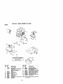
LUBRICATION CHART
Spindle _
z_
-- _) Spindle
Zerk
,";_I
:::'==== '_nt
_gront_"_
Bearing
_)Engine" ,-_'
Wheel
'_PL---------..---
I
I
ng Zerk
(_SAE 30 or 10w30 MOTOR OIL
•)Refer TO Maintenance "ENGINE"
Section
IMPORTANT: Do not oil or grease the
_ivot points which have special nylon
earings. Viscous lubricants will attract
dust and dirt that will shorten the life of
the self-lubdcatin_ bearings. If you feel
they must be lubncated, use only a dry,
powdered graphite type lubricant
sparingly.
18
"I'RACTOR
Always observe safety rules when
performing any maintenance.
BRAKE OPERATION
If tractor requires more than six (6) feet
stopping distance at high speed in
highest gear, then brake must be adjusted. (See "TO ADJUST BRAKE" in the
Service and Adjustments section of this
manual).
TIRES
• Maintain proper air pressure in all tires
(See "PRODUCT SPECIFICATIONS"
sectkm of this manual).
• Keep tires free of gasoline, oil, or insect
control chemicals which can harm
rubber.
• Avoid stumps, stones, deep ruts, sharp
objects and other hazards that may
cause fire damage.
NOTE: To seal tire punctures and prevent
flat tires due to slow leaks, tire sealant
may be purchased from your local parts
dealer. Tire sealant also preventstire dry
rot and corrosion.
OPERATOR PRESENCE SYSTEM
Be sure operator presence and intedcok
systems are working properly. If your
tractor does not function as described,
repair the problem immediately.
• The engine should not start unless the
brake pedal is fully depressed and
attechement clutch control is In the
disengaged position.
• When the engine is running, any
attempt by the operator to leave the
seat without first setting the parking
brake should shUt off the engine.
• When the engine is running and the
attachment dutch is engaged, any
attempt by the operator to leave the
seat should shut off the engine.
• The attachment clutch should never
operate unless the operator is in the
seat.
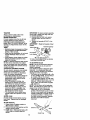
BLADE CARE
For best results mower blades must be
kept sharp. Replace bent or damaged
blades.
IMPORTANT: To ensure proper assembly,
center hole in blade must align with star
on mandrel assembly,
4. Reassemble hex bolt, lock washer
and flat washer in exact order as
shown.
5. Tighten belt securely (27-35 Ft. Lbs.
torque).
IMPORTANT: Blade bolt is grade 8 heat
treated.
MandrelAssembly
TrailingEdgeUp
Blade Center
Hole
Flat Washer
Lock Washer
_--- Hex Bolt
*A Grade 8 heat treated bolt can be identified
t_j six t_nes on the ix)It head,
TO SHARPEN BLADE
NOTE: We do not recommend sharpening blade - but if you do, be sure the
blade is balanced.
Care should be taken to keep the blade
balanced. An unbalanced blade will
cause excessive vibration and eventual
damage to mower and engine.
• The blade can be sharpened with a file
or on a grinding wheel. Do not attempt
to sharpen while on the mower.
* To check blade balance, you will need
a 5/8" diameter steel boll, pin, or a cone
balancer. (When using a cone balancer, follow the instructions supplied
with balanoer.)
NOTE: Do not use a nail for balancing
blade. The lobes of the center hole may
appear to be centered, but are not.
• Slide blade on to an unthreaded
portion of the steel boll or pin and hold
the boltor pinparallel with the ground.
If blade is balanced, it should remain in
a hodzontal position. If either end of
the blade moves downward, sharpen
the heavy end until the blade is
balanced.
BLADE REMOVAL
1. Raise mower to highest position to
allow access to blades.
2. Remove hex bolt, lock washer and flat
washer secudng blade.
3. Install new or resharpened blade with
trailing edge up towards deck as
shown.
Ce_erHde
19
BA'I-rERY
Yourtractor has a battery charging system
which is sufficientfor normal use. However, periodic charging of the battery with
an automotive charger will extend its life.
• Keep battery and terminals clean.
• Keep baftery bolts tight.
* Keep small vent holes open.
• Recharge at 6-10 amperes for I hour.
NOTE: The odginal equipment baftery on
your tractor is maintenance free. Do not
attempt to open or remove caps or covers.
Adding or checking level of electrolyte is
not
necessary.
TO CLEAN BA'I-]'ERYAND TERMINALS
Corrosion and dirt on the battery and
terminals can cause the battery to "leak"
power.
1. Open battery box door.
2. Disconnect BLACK battery cable first
then RED battery cable and remove
battery from tractor.
3. Rinse the battery with plain water and
dry.
4. Clean terminals and battery cable
ends with wire brush until bright.
5. Coat terminals with grease or petroleum jetty.
6. Reinstall battery (See "REPLACING
BA3-rERY" in the SERVICE AND
ADJUSTMENTS section of this
manual).
V-BELTS
Check V-belts for deterioration and wear
after 100 hours of operation and replace
if necessary. The belts are not adjustable.
Replace belts if they begin to slip from
wear.
TRANSAXLE COOLING
The transmission fan and cooling fins
should be kept clean to assure proper
cooling.
Do not attempt to clean fan or transmission while engine is running or while the
transmission is hot. To prevent possible
damage to seals, do not use high
pressure water or steam to clean
transexle.
• Inspect cooling fan to be sure fan
blades are intact and clean.
• Inspect cooling fins for dirt, grass
clippings and other materials. To
prevent damage to seals, do not use
compressed air or high pressure
sprayer to clean cooling fins.
TRANSAXLE PUMP FLUID
The transexle was sealed at the factory
and fluid maintenance is not required for
the life of the transaxle. Should the
transaxle ever leak or require servicing,
contact a Sears or other qualified service
center.
ENGINE
LUBRICATION
Only use high quality detergent oil rated
with API service classificationSF-SJ.
Select the oil's SAE viscosity grade
according to your expected operating
temperature.
Change the oil after every 50 hours of
operation or at least once a year if the
tractor is not used for 50 hours in one
year.
Check the crankcase oil level before
starting the engine and after each eight
(8) hours of operation. Tighten oil fin cap/
dipsticksecurely each time you check the
oil level.
TO CHANGE ENGINE OIL
Determine temperature range expected
before oil change. All oil must meet API
service classificationSF-SJ.
• Be sure tractor is on level surface.
• Oil will drain more freely when warm.
• Catch oil in a suitable container.
1. Remove oil fill cap/dipstick. Be careful
not to allow dirt to enter the engine
when changing oil.
2. Remove cap from end of drain valve
and install the drain tube onto the
fitting.
3. Unlock drain valve by pushing Inward
slightly and tumiog eeuntemiockwisa.
4. To open, pull out on the drain valve.
5. After oil has drained completely, dose
and lock the drain vaive by pushing
inward and turning clockwise until the
pin is in the locked position as shown.
6. Remove the drain tuba and replace
the cap onto to the end of the drain
valve.
7. Refill engine with oil through oil fill
dipsticktube. Pour slowly. Do not
overfill. For approximate capadty see
"PRODUCT SPECIFICATIONS"
section of this manual.
2O
8. Use gauge on oil fill cap/dipstick for
checking level, insert d_pstlck in_a the
tube and rest the oil fill cap on the
tube. Do not thread the cap onto the
tube when taking reading. Keep oil
at =FULL" line on dipstick. Tighten cap
onto the tube securely when finished.
Oil Drain Valve
TO SERVICE PRE-CLEANER
3. S_de foam pre-cLeaneroff cartridge.
4. Wash it in liquid detergent and water.
5. Squeeze it dry in a clean cloth. Allow it
to dry.
6. Saturate it in engine oil, Wrap it in
clean, absorbent cloth and squeeze to
remove excess oil.
TO SERVICE CARTRIDGE
• Replace a dirty, bent, or damaged
cartddge.
NOTE: Do not wash the paper cartridge
or use pressurized air, as this will damage
the cartddge.
7. Reinstall the pra._leener (c(eaned and
oiled) over the paper cartridge.
8. Reassemble air cleaner, wing nut,
cover and tighten knob securely.
Cap _
Cover
_
Air Cleaner
Knob
Drain Tube
CLEAN AIR SCREEN
Air screen must be kept free of dirt and
chaff to prevent engine damage from
overheating. Clean with a wire brush or
compressed air to remove dirt and
stubborn dried gum fibers.
CLEAN AIR INTAKE/COOLING AREAS
To insure proper cooling, make sure the
grass screen, cooling fins, and other
external surfaces of the engine are kept
clean at all times.
Every 100 hours of operation (more often
under extremely dusty, dirty cond_lons),
remove the blower housing and other
cooling shrouds. C_ean the cooling fins
and external surfaces as necessary.
Make sure the cooling shrouds are
reinstalled.
NOTE: Operating the engine with a
blocked grass screen, dirty or plugged
cooling fins, and/or cooling shrouds
removed will cause engine damage due
to overheating.
AIR FILTER
Your engine will not run properly using a
dirty air litter, Clean the foam pre-cleener
after every 25 hours of operation or every
season. Service paper cartridge every
100 hours of operation or every season,
whichever occurs first.
Service air cleaner more often under
dusty conditions.
1, Remove knob and cover.
2. Remove wing nut and air cleaner
from base.
Foam
Rubber
_rommet
Paper
mr Cleaner
Base
_rScmen
MUFFLER
Inspect end raptaoe corroded muffler end
spark arrester (if equipped) as it could
create a fire hazard and/or damage.
SPARK PLUGS
Replace spark plugs at the beginning of
each mowing season or after every 100
hours of operation, whichever occurs first.
Spark plug type and gap setting are
shown in "PRODUCT SPECIFICATIONS"
section ol this manual.
21
ENGINE OIL FILTER
Replace the engine oil filter every season
or every other oil change if the tractor is
used more than 100 hours in one year.
1. Drain oil from engine crankcase (See
"TO CHANGE ENGINE OIL" in this
section of this manual, through step
remove drain plug).
2. Remove oil filter and wipe off filter
adapter.
3. Apply a thin coating of new engine oil
to the robber gasket on replacement
oil filter.
4. Install replacement oil filter on filter
adapter. Turn oil filter clockwise until
rubber gasket contacts the filter
adapter, then tighten filter an additional 1/2 turn.
5. Fill crankcase with new oil (See ='1"O
CHANGE ENGINE OIL" in this section
of this manual). For approximate
capacity sea "PRODUCT SPECIFICATIONS" section of this manual.
6. Start the engine and check for oil
leaks. Correct any leaks before
placing engine into full operation.
INoLINE FUEL FILTER
The fuel filter should be replaced once
each season. If fuel filter becomes
clogged, obstructing fuel flow to carburetor, replacement is required.
1. With engine cool, remove filter and
plug fuel line sections.
2. Place new fuel filter in position in fuel
line with arrow pointing towards
carburetor.
3. Be sure there are no fuel line leaks
and damps are prepedy positioned.
4. Immediately wipe up any spilled
gasoline.
Clamp _
(_,
Fuel Filter
_)))_amp
_
--
CLEANING
all foreign
i oflean
engine,matter.
battery, seat, finish, etc.
Keep finished surfaces and wheels free
of all gasoline, oil, etc.
• Protect painted surfaces with automotive type wax.
We do not recommend using a garden
hose to clean your tractor unless the
electrical system, muffler, air filter and
carburetor are covered to keep water out.
Water in engine can result in a shortened
engine life.
22
,_
CAUTION:
1. Depress clutch/breke
BEFORE PERFORMING
pedal fully and
ANY
setSERVICE
parking brake.
OR ADJUSTMENTS:
2. Place motion control lever in neUtral (N) position.
3. Place attachment clutch in "DISENGAGED" position.
4. Turn ignition key =OFF" and remove key.
5. Make sure the blades and all moving parts have completely stopped.
6. Disconnect spark plug wire from spark plug and place wire where it cannot
come in contact with plug.
TRACTOR
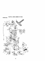
TO REMOVE MOWER
Mower will be easier to remove from the
dght side of tractor.
1. Place attachment clutch in =DISENGAGED" position.
2. Move attachment lift lever forward to
lower mower to its lowest position.
3. Roll belt off engine pulley.
4. Remove small retainer spring, and lift
clutch spdng off pulley belt.
5. Remove large retainer spdng, slide
collar off and push housing guide out
of bracket.
6. Disconnect anti-swaybar from chassis
bracket by removing retainer spring.
7. Disconnect suspension arms from
rear deck brackets by removing
retainer springs.
8. Disconnect front linksfrom deck by
removing retainer springs.
9. Raise lift lever to raise suspension
arms. Slide mower out from under
tractor.
IMPORTANT: If an attachment other than
the mower deck is to be mounted on the
tractor, remove the front links and hook
the clutch spring Into square hole in
frame.
TO INSTALL MOWER
1. Raise attachment lift lever to its
highest position.
2. Slide mower under tractor with
deflector shield to right side of tractor.
3. Lower lift lever to its lowest position.
4. Install mower in reverse order of
removal instructions.
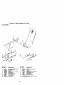
TO LEVEL MOWER HOUSING
Adjust the mower while tractor is parked
on level ground or driveway. Make sure
tires are properly inflated (Sea =PRODUCT SPECIFICATIONS" section of this
manual). If tires are over or
underinflated, you will not properly adjust
your mower.
Small Retainer Spring
Clutch Spd_ng\
Suspension Arms
Square Hole
Engine Pulley
Anti-Swa
Spdngs
(Both Sides)
Hou_ng Guide
Larg,
23
• To raise front of mower, loosen nut "P
SIDE-TO-SIDE ADJUSTMENT
from trunnion on both front links.
• Raise mower to its highest position.
Tighten nut =E_ on both front links an
• At the midpoint of both sides of mower,
equal number of turns.
measure height from bottom edge of
• When distance "D"is 1/8' to 1/2" lower
mower to groand. Distance "A" on both
at front than rear, tighten nut "P against
sides of mower should be the same or
trunnion on both front links.
within 1/4" of each other.
• Recheck side-to-side adjustment.
• If adjustment is necessary, make
adjustment on one side of mower only.
• To raise one side of mower, tighten lift
link adjustment nut on that side.
• To lower one side of mower, loosen lift
link adjustment nut on that side,
n
No'rE: Each full turn of adjustment nut
will change mower height about 1/8".
• Recheck measurements after adjusting.
Both FrontUnksShould be Equalin Length
BottomEdgeof
BottomEdge of
Mowerto Ground
Mowerto Ground
\
/
8uspension
Litt Link
Adjustment
Nut
FRONT-TO-SACK ADJUSTMENT
IMPORTANT; Deck must be level side-toside. If the following front-to-back adjustment is necessary, be sure to adjust both
front links equally so mower will stay
level side-to-side.
To obtain the best cutting results, the
mower housing should be adjusted so
that the front is approximately 1/8" to 1/2"
lower than the rear when the mower is in
its highest position.
Check adjustment on right side of tractor.
Measure distance "D" directly in front and
behind the mandrel at bottom edge of
mower housing as shown.
• Before making any necessary adjustments, check that both front linksare
equal in length.
• If links are not equal in length, adjust
one link to same length as other link.
• To lower front of mower loosen nut "E"
on both front links an equal number of
turns.
• When distance "D" is 1/8" to 1/2" lower
at front than rear, tighten nuts "P"
against trunnion on both front links.
Front
Links
Trunnion
TO REPLACE MOWER BLADE DRIVE
BELT
The mower blade drive belt may be
replaced withouttools. Park the tractor on
level surface. Engage parking brake.
BELT REMOVAL 1. Remove mower from tractor (See "TO
REMOVE MOWER" in this section of
this manual).
2. Work belt off both mandrel pulleys and
idler pulleys.
3. Pull belt away from mower.
Mandrel
Mandrel
Pulley
24
BELT INSTALLATION 4. Install new belt in reverse order of
removal.
5. Make sure belt is in all pulley grooves
and inside all belt guides.
6. Install mower in reverse order of
removal instructions.
TO ADJUST BRAKE
Yourtractor is equipped with an adjustable
brake system which is mounted on the
side of the transaxio.
If tractor mquirea more then six (6) feet
stoppingdistance at high speed in highest
gear on a level dry concrete or paved
surface, then brake must be adjusted.
1. Depress dutch_rake pedal and
engage parking brake.
2. Measure distance between brake
operatingarm and nut "A"on brake rod.
3. If distance is other then 1-9/16", loosen
jam nut and tam nut "A"until distance
becomes 1-9/16". Retightan jam nut
against nut "A".
4. Road test tractorfor proper stopping
distance as stated above. Readjust if
necessary. If stopping distance is still
greater than six (6) feet in Nghest gear,
further maintenance is necessary.
Contact a Sears or other qualified
service center.
With Parking Brake "Engaged"
Jam Nut
Operating
Arm
Do Nottouchthisnut. If furtherbcakeadjustmentis necessary,contacta Sears or other
qualh_ed
servicecenter.
TO REPLACE MOTION DRIVE BELT
Park the tractor on level surface. Engage
parking brake. For assistance, there is a
belt installationguide decal on bottom
side of left footrest.
1. Remove mower (See "TO REMOVE
MOWEFT' in this section of this
manual.)
2. Remove belt from stationary idler and
clutching idler.
3. Pull belt slack toward rear of tractor.
Carefuify remove belt upwards from
transmission input pulley and over
coaling fan blades.
4. Pull belt toward front of tractor and
remove downward from around
engine pulley.
5. Install new belt by reversing above
procedure.
Engine
Pulley
.__
ClutchingIdler__
...___ I &
StationaryIdler-__.. _@[
InputPulley
Transmission
TRANSAXLE MOTION CONTROL
LEVER NEUTRAL ADJUSTMENT
The motion control lever has been preset
at the factory and adjustment should not
be necessary.
1. Loosen adjustment bolt in front of the
right rear wheel, and lightly tighten.
2. Start engine and move motion control
lever until tractor does not move
forward or backward.
3. Hold motion control lever in that
position and tum engine off.
4. While holding motion control lever in
place, loosen the adjustment bolt.
5. Move motion control lever to the
neutral (N) (lock gate) position.
6. Tighten adjustment bolt securely,
NOTE: If additional clearance is needed
to get to adjustment bolt, move mower
deck height to the lowest position.
After above adjustment is made, if the
tractor still creeps forward or backward
while motion control lever is in neutral
position, follow these steps:
1. Loosen the adjustment bolt.
25
2. Move the motion control lever 1/4 to
1/2 inch in the direction it is trying to
creep.
3. Tighten adjustment bolt securely.
4. Start engine and test.
5. If tractor still creeps, repeat above
steps until satisfied.
MotionControl
Neu_'alLock Gate
Lever
RetainingRingWa_"ere
Square Key
--.-----_'
_'/_Y
(Rear Wheel Only)
TO START ENGINE WITH A WEAK
BATTERY
e_CA.UTION:
batteriesgenerate
xplodvegases.L.epd-acid
_,eap spad,.s,
flam_ and
smoldngmaterials away from batteries.
Alwayswear eye protectionwhen around
batteries.
If yourbatteryistoo weak tostartthe an_ine, it
shouldbe recharged.(See "BATTERY"in the
MAINTENANCE sectionof thismanual).
If "jumper cables"are usedfor emergency
starting,folow this prosedure:
IMPORTANT: Yourtractoris equippedwitha
12 voltnegativegroundedsystem.The other
vehicalmust also be a 12 voltnegative
groundedsystem.Do notuse yourtractor
battery to startother vehicles.
TO ATrACH JUMPER CABLES 1. Connect each end of the RED cable to
the POSITIVE (+) terminal of each
battery, taking care not to short
against chassis.
2. Connect one end of the BLACK cable
to the NEGATIVE (-) terminal of fully
charged battery.
3. Connect the other end of the BLACK
cable to good CHASSIS GROUND,
away from fuel tank and battery.
TO REMOVE CABLES, REVERSE ORDER.
1. BLACK cable first from chassis and
then from the fully charged battery.
2. RED cable last from both battedea.
TRANSMISSION REMOVAUREPLACEMENT
Should your transmission require
removal for service or replacement, it
should be purged after reinstallation and
before operating the tractor. See
"PURGE TRANSMISSION" in the
Operation section of this manual.
TO ADJUST STEERING WH EEL ALIGNMENT
If steedng wheel crossbars are not
horizontal (left to right) when wheels are
positioned straight forward, remove
steering wheel and reassemble per
instructionsin the Assembly section of
this manual.
FRONT WHEEL TOE-IN/CAMBER
The front wheel toe-in and camber are
not adjustable on your tractor. If damage
has occurred to affect the front wheel toein or camber, contact a Sears or other
qualified service center.
TO REMOVE WHEEL FOR REPAIRS
1. Block up axle securely.
2. Remove axle cover, retaining ring and
washers to allow wheal removal (rear
wheel contains a square key - Do not
lose).
3. Repair tire and reassemble.
NOTE: On rear wheels only: align
grooves in rear wheel hub and axle.
Insert square key.
4. Replace washers and snap retaining
dng securely in axle groove.
5. Replace axle cover.
NOTE: To seal tire punctures and prevent
flat tires due to slow leaks, tire sealant
may be purcbesed from your local parts
dealer. Tire sealant also prevents tire dry
rot and corrosion.
',ables
Positive
26
Charged
Batlery
Termini
TO REMOVE HOOD AND GRILL ASSEMBLY
1. Raise hood.
2. Unsnap headlight wire connector.
3. Stand in front of tractor. Grasp hood at
sides, tilt toward engine and liftoff of
tractor.
4. To replace, reverse above procedure.
REPLACING BA'ZrERY
_-_CAUTION: Do not short battery
terminals by allowing a wrench or any
other object to contact both terminals at
the same time. Before connecting battery,
remove metal bracelets, wristwatch
bands, rings, etc.
Positive terminal must be connected first
to prevent spaddng from accidental
grounding.
1. Lift seat pan to raised position and
open battery box door.
2. Disconnect BLACK battery cable first
then RED battery cable and carefully
remove battery from tractor.
3. install new battery with terminals in
same position as old battery.
4. First connect RED battery cable to
positive (+) terminal with hex bolt and
keps nut as shown. Tighten securely.
5. Connect BLACK grounding cable to
negative (-) terminal with remaining
hex bolt and keps nut. Tighten
securely.
6. Close battery box door.
_
H:e_°ddlight
Wire
ector
ENGINE
Maintenance, repair,or replacementof the
emissioncontroldevicesand systems,which
are beingdone at the customersexpense,
may be performedby any non-readengine
repairestablishmentor individual.Warranty
repairsmast be performed by an authorized
engine manufactorafs serviceoufieL
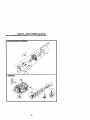
TO ADJUST THRO'rFLE CONTROL
CABLE
The throttleccntroi has been presetat the
factoryandaclus'cnentshouldnot be
necessary.Check a_ustment as described
belowbefore_
c_ole.
If adjuslmentis
necessary,proceedas follows:
1. W'dhengine notrunning, move throttle
centrolleverfrom slewto choke pesi_on.
Slowlymove leverfrom choketo fast
pesr_.
positive(Red) Cable Negative(Black)Cable
TO REPLACE HEADLIGHT BULB
1. Raise hood.
2. Pull bulb holder out of the hole in the
backside of the grill.
3. Replace bulb in holder and push bulb
holder securely back into the hole in
the backside of the gdlL
4. Close hood.
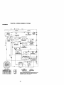
INTERLOCKS AND RELAYS
Loose or damaged widng may cause your
tractorto run poorly,stop running, or
prevent it from starting.
• Check widng. See electdcat wiring
diagram in the Repair Parts section.
TO REPLACE FUSE
Replace with 20 amp automotive-type
plug-in fuse. The fuse holder is located
behind the dash.
2. Checkto sse if holein throttleleverand
hole in speed co_
bracket are aligned.
3. If holesare not aligned, loosencable
screw _md align the holes by
insertinga pencilor a 1/4" dnllbit througfl
b_ holes.
4. Pul throttle cable up to remove slackand
tighten cableclamp screw. Remove
aignmant p_x:il or ddl bit.
27
Cable
Clam
Screw
Speed Control
Bracket
Throttle Lever
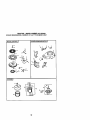
TO ADJUST CARBURETOR
The carburetorhas been presetat the facto_
and adjustment shouldnot be necessary.
However,minor aclustmentmay be required
to compensate for differencesin fuel,
temperature,altitudeor load. If the carburetor
does need adjustment,proceed as folows:
In general,turn_g the adju._ng needles In
(dock-wise)decreases the supplyof fuelto
the enginegivinga leaner tueVaJrmixture.
Turningthe acyustJngneedles out (countor.
_se)
increasesthe supplyof fuelto the
engine givinga richerfuel/airrK_xtu
re.
IMPORTANT: Damage to the needlesand
seats in carburetor may result if turned in too
tight.
NOlle: The carburetor on this engine islow
emission.It is equippedwith an idlefuel
aclusfing needlewith a imiter cap, which
alows some adjus'a'sent
withinthe limits
alowed by the cap. Do notattemptto remove
the rr,iter cap. The Iknitercap cannotbe
removed without breakingthe a_usltng
needle.
1. Besure you have a dean air filterand the
throttlecontrolcableis adjustedproperly
ACCELERATION TEST 6. Move threttle control leverfromsJowto
fastposition.If engine hesitates or des,
turn idlefuel a_usting needle out
(caunterdockwise) 1/8 turn. Repeat test
andcan'_nueto adjust,if necessary,until
engi'_eacceleratessm(x_ly.
High speed stop is factory adjusted. Do
not adjust - damage may result.
IMPORTANT: Never tamper with the
engine governor, which is factory set for
proper engine speed. Overspeeding the
engine above the factory high speed
setting can be dangerous. If you think the
engine-governed high speed needs
adjusting, contact a Sears or other
qualified service center, which has proper
equipment and expedenca to make any
necessary adjustments.
Idle Speed
Adjusting -.........._
s_rew_
(seeabove).
2. Startengineand alow to warmfor five
minutes.Make ad_ts
with engine
running and shlttffnet_ control lever in
neutral(N) pesllJon.
3. Idlespeed setting- VWhthrottlecontrol
leverin slow posi_on,engine shouldidle
at 1750 RPM. If engine idlestooslowor
fast, turnidle speed adjus,ng screw in or
outurCdl
correctidle is attained.
4. IdlefuelneedlesetlJno- W'ith_rctUe
conlrollever in slowposition,turn idle fuel
a_ustment needle in (dockwise)anIfl
enginebeans to die and than turn out
(counterclockwise)untilengine runs
rough.Turn needle to a pointmidway
IdleFuel
betweanthosetwopsei_r_.
5. Reched<idlespeed. Rea(_ust if neces.
saty.
28
Immediately prepare your tractor for
storage at the end of the season or if the
tractor will not be used for 30 days or
reOre,
CAUTION: Never store the tractor
with gasoline in the tank inside a building
where fumes may reach eJnopen flame or
spark. Allow the engine to cool before
storing In any enclosure.
TRACTOR
Remove mower from tractor for winter
storage, When mower is to be stored for
a period of time, clean it thoroughly,
remove all dirt. grease, leaves, etc. Store
in a clean, dry area.
1. Clean entire tractor (See "CLEANING"
in the Maintenance section of this
manual).
2. Inspect and replace belts, if necessary
(See belt replacement instructionsin
the Service _d Adjustments section
of this manual).
3. Lubricate as shown in the Maintenance section of this manual.
4. Be surothat all nuts, botts and screws
are securely fastened. Inspect moving
parts for damage, breakage and wear.
Replace if necessary,
5. Touch up all rusted or chipped paint
surfaces; sand lightly before painting.
BA'I-I'ERY
• Fully charge the battery for storage.
• After a period of time in storage, battery
may require recharging.
• To help prevent corrosion and power
leakage during long pedods of storage,
battery cables should be disconnected
and battery cleaned thoroughly (see
"TO CLEAN SA'N'ER¥ AND TERMINALS" in the Maintenance section of
this manual).
• After cleaning, leave cables disconnected and place cables whore they
cannot come in contact with battery
terminals.
• If battery is removed from tractor for
storage, do not store battery directly on
conorate or damp surfaces.
ENGINE
FUEL SYSTEM
IMPORTANT: It Is important to prevent
gum deposites from forming in essential
fuel system pa_s such as cad_retor, tael
hose, or tank during storage.
Also, expedanco indicates that alcohol
blended fuels (called gasohol or using
ethanol or methanol) can attract moisture
which leads to separation and formation
of acids during storage. Acidic gas can
damage the fuel system of and engine
while In storage.
1. Drain the fuel taP_..
2. Start the engine and let it run until the
fuel lines and carburetor are empty.
• Never use engine or carburetor cleaner
products in the rue! tank or permanent
damage may occur.
• Use fresh fuel next season.
NOTE: Fuel stabilizer is an acceptable
alternative in minimizing the formation of
fuel gum deposits during storage. Add
stabilizer to gasoline in fuel tank or
storage container. Always follow the mix
ratiofound on stabilizer container. Run
engine at least 10 minutes after adding
stabilizer to allow the stabilizer to reach
the carburetor. Do not drain the gas tank
and carburetor if using fuel stabilizer.
ENGINE OIL
Drain oil (with engine warm! and replace
with clean engine oil. (See ENGINE in
the Maintenance section of this manual).
CYLINDER(S)
1. Remove spark plug(s).
2. Pour one ounce of oil through spark
plug hole(s) into cylinder(s).
3. Turn ignition key to =START" position
for a few seconds to distributs oil.
4. Replace with new spark plug(s).
OTHER
• Do not store gasoline from one season
to another.
• Replace your gasoline can if your can
starts to rast. Rust ar,,d/ordirt in your
gasoline will cause problems.
• If possible, store your tractor indoors
and cover it to give protection from dust
and dirt.
• Cover your tractor with a suitable
protective cover that does not retain
moisture. Do not use plastic. Plastic
cannot breathe which allows condensation to form and will cause your
tractor to rust.
IMPORTANT: Never cover tractor while
engine and exhaust areas are still warm.
29
TROUBLESHOOTING
CHART
PROBLEM
Wllln_start
CAUSE
1. Out of fuel.
2. Engine not "CHOKED"
properly.
3. Engine flooded.
Hard to start
1.
2.
3.
4.
5.
CORRECTION
1. Fill fuel tank.
2. See "TO START ENGINE"
in Operation section.
3. Wait several minutes before
attempting to start.
4. Bad spark plug.
4. Replace spark plug.
5. Dirtyair filter.
5. Clean/replace air filter.
6. Dirtyfuel filter.
6. Replace fuel filter.
7. Water in fuel.
7. Drain fuel tank and carburetor, refill tank with fresh
gasoline and replace fuel
filter.
8. Loose or damaged wiring.
8. Check all widng.
9. Carburetor out of adjuetment. 9. See "To Adjust Carburetor"
in Service Adjustments
section.
10.Enginevalvesout of
lO.Contact a Sears or other
adjustment.
qualified service center,
Dirty air fiifer.
Bad spark plug.
Weak or dead battery.
Dirty fuel filter.
Stale or dirty fuel.
6. Loose or damaged widng.
7. Carburetor out of adjustment.
8. Engine valves out of
adjustment.
Englnawlllnot
turn over
1. Clutch/brake pedal not
depressed
2. Attachment clutch is
engaged.
3. Weak or dead battery.
4. Blown fuse.
5. Corroded battery terminals.
6. Loose or damaged wiring.
7. Faulty ignition switch.
1.
2.
3.
4.
5.
Cleaniraplace air filter.
Replace spark plug.
Recharge or replace battery.
Replace fuel filter.
Drain fuel tank and refill with
fresh gasoline.
6. Check all wldng.
7. See "To Adjust Carburetor"in
Service Adjustments
section.
8. Contact a Sears or other
qualified service center.
1. Depress clutch/brake pedal.
9. Faulty operator presence
switch(es).
2. Disengage attachment
clutch.
3. Recharge or replace battery.
4. Replace fuse.
5. Clean battery terminals.
6. Check all widng.
7. Check/replace Ignition
switch,
8. Check/replace solenoid or
starter.
9, Contact a Sears or other
qualified service center.
Engine clicks but
will not start
1.
2.
3.
4,
1.
2.
3.
4.
Loss of power
1. Cutting too much grass/too
fast.
2. Throttle In "CHOKE"
position.
8. Faulty solenoid or starter.
Weak or dead battery.
Corroded battery terminals.
Loose or damaged widng.
Faulty solenoid or starter.
3O
Recharge or replace battery.
Clean battery terminals.
Check all widng.
Check/replace solenoid or
starter.
1. Set in "Higher CUt" position/
reduce speed.
2. Adjust throttle control.
TROUBLESHOOTING
CHART
PROBLEM
CAUSE
CORRECTION
Loss of power
(continued)
3. Build-up of grass, leaves
and trash under mower.
4. Dirty air filter.
5. Low oil leveVdirty oil.
6. Faulty spark plug.
3. Clean underside of mower
housing.
4. Clean/replace air filter.
5. Check oil level/change oil.
6. Clean and regap or change
spark plug.
7. Replace fuel filter.
8. Drain fuel tank and refill
with fresh gasoline.
9. Drain fuel tank and
carburetor, refill tank with
fresh gasoline and replace
fuel filler.
10.Connect and tighten spark
plug wire.
11. Clean engine air screen/
fins.
12. Clean/replace muffler.
13.Check all widng.
14. See "To Adjust Carburetor"
in Service Adjustments
section.
15.Contact a Sears or other
qualified service center.
7. Dirtyfuel filler,
8. Stale or dirty fuel.
9. Water in fuel.
1O.Spark plug wire loose.
11. Dirty engine air screen/fins.
12. Dirty/clegged muffler.
13. Loose or damaged wiring.
14.Carburetor out of
adjustment.
15.Engine valves out of
adjustment.
Excessive
vlbr_lon
1_ Worn, Pent or loose blade.
2. Bent blade mandrel.
3. Loose/damaged part(s).
Engine conUnuea
to run when
;operator leaves
seat with
attachment
clutch engaged
Poorcut-uneven
1. Faulty operator-safety
presence control system.
1. Check wiring, switches and
connections. If not corrected
contact a Bears or other
qualified service center.
1. Worn, pent or loose blade.
1. Replace blade. Tighten
blade bolt.
2. Level mower deck.
3. Clean underside of mower
housing.
4. Replace blade mandrel.
5. Clean around mandrels to
open vent holes.
2. Mower deck not level.
3. Buildup of grass, leaves,
and trash under mower.
4. Bent blade mandrel.
5. Clogged mower deck vent
from build-up of grass,
leaves, and trash around
mandrels.
Mower blades will
not rotate
1. Replace blade.
Tighten blade bolt.
2. Replace blade mandrel.
3. Tighten loose part(s).
Replace damaged parts.
1. Obstruction in clutch
mechanism.
2, Worn/damaged mower
drive belt.
3. Frozen idler pulley.
4. Frozen blade mandrel.
31
1. Remove obstruction.
2. Replace mower ddve bell.
3. Replace idler pulley.
4. Replace blade mandrel.
TROUBLESHOOTING
CHART
PROBLEM
CAUSE
CORRECTION
Poor grass
discharge
1. Place throttle control in
"FAST"position.
2. Travel speed too fast.
2. Shift to slower speed.
3. Wet grass.
3. Allow grass to dry before
mowing.
4. Mower deck not level.
4. Level mower deck.
5. Low/uneven tire air pressure. 5. Check tires for proper air
pressure.
6. Worn, bent or loose blade.
6. Replace/sharpenblade.
Tightenbladebolt.
7. Buildup of grass, leaves and 7. Clean undersideofmower
trash under mower.
housing.
8. Mower drive belt wom.
8. Replacemower drivebelt.
9. Blades improperly installed. 9. Reinstall blades sharp edge
down.
10.Improper blades used.
10.Replace with blades listed
in this manual.
11. Clogged mower deck vent
11.Clean around mandrels to
holes from buildup of
open vent holes.
grass, leaves, and trash
around mandrels.
Headlight(s) not
worldng
(if so equipped)
1.
2.
3.
4.
1. Engine speed too slow.
Switch is =OFF'.
Bulb(s) or lamp(s) burned out.
Faulty light switch.
Loose or damaged widng.
5. Blown fuse.
Battery will not
charge
I. Bad battery cell(s).
2. Poor cable connections.
3. Faulty regulator
(if so equipped).
4. Faulty alternator.
Loss of drlve
Engine"backfires"
whentumlng
engine
"OFF"
1.
2.
3.
4.
Turn switch =ON".
Replace bulb(s) or lamp(s).
Check/replace light switch.
Check widng and connections.
5. Replace fuse.
1. Replace battery.
2. Check/clean all connec.
tions.
3. Replace regulator.
4. Replace alternator.
1. Freewheel control in
"disengaged" position,
2. Motion drive belt wom,
damaged, or broken.
3. Air trapped in transmission
during shipment or
servicing.
1. Place freewheel control in
"engaged" position.
2. Replace motion drive belt.
1. Engine throttle control not
set at "SLOV_"
position for 30 seconds
before stopping engine,
1. Move throttle control to
=SLOW_ position and allow
to idle for 30 seconds before
stopping engine.
32
3. Purge transmission.
TRACTOR -- MODEL NUMBER 917,272063
SCHEMATIC
1 1111 -
i
BA3"rERY
AMMETER
S_.ENG_D
FUSE
i
'l
STAR_.R
(OP110NAL)
_?____].
i
_......
,
......
,
,'_'.......
--.'
,_"_"
i
*
CLUTCH
OF._F)
.........
- - SP'cATS_TCH
IG NITI_I
I
(NOT OCCUPIE_D)
;
,1
!' _i
v
L
SOLENCID
(IF so EQUIPPED)
___ll
_
_
mJ_
PRESENCE RELAY #1
KUE ItL_
86 I
'_©
87A
i
IGNmON
UNrr
IESENCE RELAy #2
PLC_
l_Nt (2NPLUGS
SPARK ON
i_
_q_w°
sYm
°_J_
REGULATOR
iI
•
I
yI_LLOW
.......
PRESENCE RELAY #3
HEAD'UGHTS
IGNmON
Posfno_l
SWITCH
CIRCIIT
"MAKE*
OFF
M_AI
RUN,IJGHT B*_AI
RUN
B_.A1
START
B÷S+A1
A2..L
N_NE
NOME
NON-REMOVABLE
CONNECTIONS
RELAY
REMOVABLE
CONNECTIONS
WIRING INSULATED CUPS
NOTE: IF WIRING INSULATED CLIPS WERE REMOVED FOR
SERVICING OF UNIT, THEY SHOULO BE REPLACED TO
PROPERLY SECURE YOUR WIRING*
33
TRACTOR -- MODEL NUMBER 917.272063
ELECTRICAL
i
t
i
i
i
i
i
I
I
i
i
i
/J
iI
t
J
34
TRACTOR -- MODEL NUMBER 917.272063
ELECTRICAL
KEY
NO.
1
2
8
18
21
22
24
25
28
27
28
29
30
33
40
41
42
43
45
52
81
PART
NO.
163465
74760412
156417
161343
166182
4152J
4799,1
146147
175158
73510400
4207J
160784
175,5_6
1404_
178438
71110408
131563
175141
122822X
141940
1_'748X
DESCRIPTION
BatteW 12 Vdit 28 Amp
Bolt, Hex Head 1/4-20 uric x 3/4
Case, Balte W Mech Hinge
Switch. |ntedock N Opn/N Opn
Harness, Light Socket (Includes 4152J)
Bulb, Light
Cable, Batter/, 6 Gauge, Red, 11
CabLe, Battew, 6 Gauge, Red, W/16 Wire
Fuse,20 Amp
Nut Keps Hexl/4-20 Unc
Cable, Ground, 6 Gauge, Black, 12"
Switch, Plunger Normal Op Olive
Switch, Igditlon
Key, Igditlon
Harness, Ignition
Bolt, Hex Head, Fin. 1/4-20 x 1/2
Covet, Termlndi, Red
Solenoid
Ammeter Rectangular
Protection WIm Lcop
Relay Asm.
NOTE: All component dimensions given in U.S. Inches
I inch = 25.4 mm
35
TRACTOR
-- MODEL NUMBER 917.272063
CHASSIS AND ENCLOSURES
12
gV '5
2O8
9
207
,
64
13 "WO
•
"__"
•
" _'_':",,i__,
'" _;"' '
_
3
37
I
t
145
37
2O8
136
TRACTOR -- MODEL NUMBER 917.272063
CHASSIS AND ENCLOSURES
KEY PART
NO. NO.
1
2
3
5
g
10
11
12
13
14
17
18
25
26
28
29
30
31
37
38
51
52
53
54
55
57
58
6O
64
74
142
143
144
145
159
2O6
2O7
2(;8
212
..
NOTE:
DESCRIPTION
174619
176554
17060612
155272
166O37X013
STD533710
155927
145660
172107xg10
1746O608
144983X558
126938X
19131312
S'1_541437
156725X558
155217X599
1756O2X56O
139976
17490508
175710
Chassis Stamping
Dr_=
Screw 3/8-16 x 3/4
BuroperHood/Dastl
Dash
Bolt, Can]age 3/8-16xl
Panel, Dash, LH.
Clip Tlnnmman Gdlle P/1.
Panel, Dash, R.H.
Screw Thdml 3/8-16 x 1/2
Hood Assembty
BumperHood
Washer 13/32 x 13/16 x 12 Gauge
Nut
Gdlle Lens Asm
Lans, Gdlle
Fend/Ftreet Pnt STLT
Bracket, Fender Suppod
Screw Ti_drol 5/16-18 x 1/2 Tyt
Bracket Asrn. Pivct Mower Rear
Nut Lock w/Insed 1/4-20 UNC
19091416
Washer 9/32 x 7/8 x 16 Ga.
145201
Bracket Grille Pickotf LH
161464
Screw Hex Wshd 8-18 x 7/_
145202
Bracket Grille Pickeff RH
S]O522507
Belt, Fin Hex 1/4-20 UNC x .75
150127
Duct Air Engine P/L LT
72140606
Belt Rdhd Sqnk 3/8-16 UNC x 3/4
154798
Dash Lower 8_.T
73680600
Nut Crownlock 3/8-16 UNC
165867
Plate Reinforcement STLT
154966
Bracket Swaybar Chessls
175582
Bracket Pnt Footrest STLT
156524
Jod Pivot ChaselsJHood
155123X428 Cuphelder
170165
Belt Shoulder 5/16 -18 Tr
17670508
Screw Tildrol 5J16-18 x 1/2 TYTT
17670608
Screw "l_drol 3/_-16 x 1/2
165919
Insed Lens Reflective
5479J
Plug, Button
All component dimensions given in U.S. Inches
1 Inch = 25.4 mm
37
TRACTOR-MODEL
NUMBER
917.272063
GROUND
DRIVE
35
32
36
16 3_
52
/_32
30
26
TRACTOR - - MODEL NUMBER 917.272063
GROUND DRIVE
KEY
NO,
PART
NO,
1
......
8
10
14
15
16
19
21
22
24
25
26
27
28
29
30
:_
34
35
36
37
38
39
40
41
42
47
48
49
50
51
52
53
55
56
57
52
61
52
52
64
165866
STD561210
10040400
744_T_14
$10541431
STD541437
13(To64
169498
73350600
1G6888X
STD551_
STD561210
175765
71673
169592
74765512
175578
120183X
19211616
1572H
165936
74760648
175461
175556
19131312
127783
154407
123255X
S'i_523715
S_)541437
STD541431
105710X
10_709X
1706(;616
140294
152691
1706G612
8883R
175410
71170764
KEY
NO.
DESCRIPTION
T_le
(See Breakdown)
HydmGr 314-C510
ROd Shift Fender Adjust
PInCo6er 1/8x I CAD
Washer Lock Hvy Helical
Bo_ Hex FLGHD 5/16-18 x Gr 5
Nut Lock Hex W/Ins. 5/18-18 Unc
NutLcckHexW/Wsh
3/6-16Unc
Knob, Deluxe 1/2-13
Rod, Brake Hydro
Nut, Hex Jam 5/8-16 Unc
Spdng, Brake ROd
Washer
Pin Coder 1/8 x 5/4 CAD.
Rod, parking Brake
Cap, Parking Brake
Bracket, Transaxle
Bolt Hex Hd 5/16-18 Unc x 314
Shag, Foot Poddl
Beadng, Nylon
Washer
Pin, ROO]
Pulley, Composite, Flat
BoOtFin Hex 3/6-16 x 2-3/4
Spacer, Sp_lt
Keeper, Belt idler
Washer 13/32x13/16x12Ga.
Pulley, Idler, V+Groove
Rdllcmnk, Clutch
Retainer, Belt
Bolt Hex Hd 3/6-16 x 1-1/2
NutCrown_ock 3/6-16UNC
Nut, Crowdlock 5/16-18 Unc
Link, Clutch
Sprlng_ Return, Clutch
Screw 3/8-16 x 1.04
V-Bdlt
Keeper, Center Span
Screw. 3/6-16x3/4
Cover, Pedal
Pulley, Engine
Bolt Hex 7/16-20 x 4 Gr. 5
52
66
70
71
73
74
75
76
77
78
81
82
83
84
89
90
55
96
113
120
150
151
156
156
159
161
162
163
164
165
166
168
169
197
198
152
200
2(_
212
PART
NO.
STD551143
154778
134683
169152
1691_
137057
121749X
STD581075
123583_
121748X
165552
165711
19171216
169594
164890X428
124346X
17_01
4497H
72140606
73900600
175456
19133210
1660(_
165552
165494
72140406
73680400
74780416
19091010
165523
188880
16_
165552
169613
169552
169612
72140506
72110614
145212
DESCRIPTION
washer
Keeper Belt Engine Hydro
Keepar Belt Engine
Strap Torque Lh Hydro
Strop Torque Rh Hydro
Spacer
Washer 23/32 x 1-1/4 x 16 Gauge
E-Ring
Key, Square
Washer 23/32 x 1-5/8 x 16 Gauge
Shaft Asm Cross Tapered
SpltngTorslon
Washer 17,'32 x 3/4 x 16 Ga.
Unk Transaxle
Console, Shift
NUtSelt-Tnd Wsh-hd 1/4 Zinc
Control Bypass Hydro 20" _res
Retdlner Spring 1" Zinc/Cad
Bolt Rdhd Sqneek 3_-16 x 1.25
NUt Lock Fig 3/8-16
Spacer Retainer
Washer 13/32 x 2 x 10 Ga.
Washer Brdod 5/161D x 1.125
Bracket Shilt Mount
Hub Tapered Flange Shift Lt
BOOtRdhd Sqnk 1/4-20 x 3/4 Gr 5
Nut Cmwnlock 1/4-20 Unc
Bolt Hex Fin 1/4-20 Unc x 1 Gr 5
Washer 5/8 x .281 x 10 Ga
BraCXel Pivot Lever
Screw 5/16-18 x 5/8
Bolt Shoulder 5/1 6-18 x .561
Plate Fastening
Hyllner Snap-In 5/8"1D
Washer Nyl 7/8 ID x +155" Hyd
Bolt Shoulder 5/16-18UNC
Bdlt Rdhd Sgnk 5116-18UNC x 1
BOOtCarr Sh 3/8-1 6 x 1-3/4Gr.5
Nut Hex Fig. Lock
NOTE: All component dimensions given in U.S.
inches 1 inch = 25.4 turn
39
TRACTOR
-- MODEL
NUMBER 917.272063
STEERING ASSEMBLY
i
..p
\
'\
'\
4O
TRACTOR - - MODEL NUMBER 917.272063
STEERINGASSEMBLY
KEY PART
NO. NO.
1
2
3
4
5
6
7
8
9
10
11
13
15
17
26
28
29
30
39
36
37
38
39
40
41
42
43
44
46
47
51
54
63
65
67
68
71
39
85
88
91
139768
154427
169840
169839
6266H
121748X
19272016
12000029
3366R
175121
Sr[T.351137
136518
145212
177876
126847X
19131415
17060612
STD561210
130465
1_
152927
139769
1913,3812
$1IT041537
100711L
145054x428
121749X
153720
121232X
6855M
STD541431
74780520
$1_523710
16GG67
72140618
169827
175146
169835
133835
175118
175553
DESCRIPTION
Steedng Whedi
Axle Assembly STMP Dropped STL
Spindle Assembly, LH.
Spindlo Assemb_, R.H.
Beadng, Race, Thrust. Hardennd
Washer 25/32 x 1-5/8 x 18 Gauge
Washer 27/32 x 1-1/4 x 16 Gauge
Ring. Klip
Beartng, Stee ring Column
Draglnk
Washer, Lock
Spacer Brg Axle Front
Nut, Hextlange Lock
Shaft Assembly, Steering
Bushing, Unk, Drag
Washer 13/32 x 7/8 x 16 Gauge
Screw 3/8-16 x 3/4
Pin
Rod,_e
Bushing, Steerlr_g
Screw
Insert, Steering Wheol
Washer 13/32 x 2-3/8 x 12 Gauge
Nut LockCenter3/_8-24UNF
Adaptor. Stendng Wheel
Boot, Steedng Shaft
Washer 25/32 x 1-1/4 x 16 Gauge
Extension Shaft Steedng LR.LT
Cap.Spindle
Fitting, Grease
NutLockHexw/Ins.
5/16-18UNC
Bolt Fin Hex 5/16-18 UNC x 1-1/4
Bstt, Fin Hex 3/8-16 UNC x 1Gr 5
Spacer Brace Axle
Bolt Rdhd Sqnk 3/8-16 x 2-1/4
Axle, Brace
Steedng Asm
Bracket Susp Chassis Front
Fastner ChdstmasTree
Bnd Shodider 7/16-20
Clip Steedng
NOTE:/UI component dimensions given in U.S. inches
1 Ioch = 25.4 mm
41
TRACTOR
-- MODEL
NUMBER
917.272063
SEAT
ASSEMBLY
KEY PART
NO. NO.
DESCRIPTION
1
2
3
4
5
9
7
8
9
10
11
12
Seat
Bracket, Pivot, Seat
Bolt
Washer 13/32 xl x 10Gauge
Clip, Push-In HingeS
Nut
Spring, Seat
Sc;'ew 3/8-16 x 1-1/2
Washer 13/32x1 x14Gauge
Pan, Seat
Knob Seat
Bracket, Switch Mounting
140123
14_551
71110616
19131610
145006
ST[To41437
124181X
17(;00616
19131614
174894
166369
121246X
KEY PART
NO. NO.
DESCRIPTION
13
14
t5
16
17
21
22
24
25
Bushing, Snap
BoR, Cardage 1/4-20 x 1-1/2
Spacer, Sl_it .28 x .88
Spring
Locknut, Range 1/4 Grade 5
Bolt, Sheulder 5/16-18 UNC
Nut
Washer 17/32x 1-3/19x 12Ga.
Bolt, Shoulder 5/16-18x.62
121248X
72050412
134300
121250X
12397_(
171852
S'1I)54143t
19171912
127018X
NOTE: All component dimensions given in U,S.
Inche_ 1 Inch = 25.4 rnrn
42
TRACTOR - - MODEL NUMBER 917.272063
DECALS
10
9
13
KEY
NO.
PART
NO,
1
2
3
4
5
6
7
8
9
10
12
156811
177368
171698
171699
171765
133644
177325
172331
163204
1E6439
146046
3
7
7
DESCRIPTION
Decal, Oper. Instr.
Decal, HP Engine
Decal, Hood, R.H.
Decal, Hood, LH.
Decal Hood Replacement
De cal, Custorner Malnte nance
Decal, Hood Side
DeCal, Deck
Decal, Fender, Craftsman
Decal, Fender Danger
Decal, V-Belt Drive Schematic
WHEELS &TIRES
4
13
16
20
KEY
NO.
PART
NO.
DESCRIPTION
13
14
16
20
-------
177336
16(_96
138047
1411516
138311
165800X428
165799X428
169210
178453
178454
Deca], Lower Dash
Decal, V-Belt Schematic
Decal, Battery Olehmd
Decal, BatteP/Dngr/Psn Eng
Decal, Lift Handie
Pad Footrest LH STLT
Pad Footrest RH STLT
Decal By Pass LT Hydro
Owner's Manual, English
Owner's Manual, Spanish
KEY PART
I_
2_
5
5,8
4,10
11
NO,
NO,
DESCRIPTION
1
5918_
Valve Cap, 11re
2
3
4
65139
106222)(
59904
5
6
7
10673_X427
278H
9040#-I
Stem, Valve
Tire, Front
Tube, Front Tire
(Not Provided, Sendce Item Only)
Rim, Front
Fitting, Grease (Front Wheel Only)
Beadng, Flange (Front Wheel
8
9
10
lg6108X427
122(_2X
7152J
11
--
104757)(428
144334
On_
Rim, Rear
13re, Rear
Tube, RearTire
(Not Provided, Service Item Only)
Cap, Axle
Sealant, Tire 10 oz.
NOTE: Ag component dimensions given in U.S.
inches 1 inch = 25.4 mm
43
TRACTOR - - MODEL NUMBER 917.272063
ENGINE
38
4
14
_'_33
29
\
OPTIONAL
EQUIPMENT
Spark Attester
KEY pART
NO. NO.
1
2
170548
17720410
3
......
4
13
14
16
23
29
31
32
33
3;"
159420
12-041-03
148456
_1_551237
1_837
137180
10_02X
158990
1234877(
137040
KEY pART
NO. NO.
DESCRIPTION
Control,Throttle
Screw, Hex Head, Thread Cutting
1/4-20 x 5/8
Engine, (See Breakdown) Kohler
Model No. CV16.5-43527
Muffler
Gasket Kohler
Tube Drain Oil E_sy
Washer
Shield Bm/Dbr Guard
Arrestor, Spark
Tank, Fuel
Cap AssembJy, FueJ Sears, Vented
Clamp, Hc_e
Line, Fuel
40
44
148315
124028x
17670412
45
46
77
80
81
101
1(;5
17000612
19(391416
lg101216
74760508
735104_0
M_
1712C616
DESCRIPTION
Plug, Drain Oil Easy
Bushing, Snap, Fuel Line
Screw, Hex Washer Heed, Thd.,
Roll. 1/4-20 x _/4
Screw Hex Wsh Ttldr 3/8-t6 x 3/4
Washer 9/32 x 7/8 x 16 Gauge
Washer 5/16 x 3/4 x 16 Ga.
Bait Hex Hd 5/16-18 Unc x 1/2
Nut Keps Hex 1/4-20Unc
Nut Flan-ge M5-1.25 NotpLk Zinc
Screw 3/_-16 x I
NOTE: All component dkllerls[or_ given in U.S. inches
I inch = 25.4 mm
44
TRACTOR
-- MODEL
NUMBER 917.272063
LIFTASSEMBLY
7
13
11__12
6
KEY PARr
NO, NO.
DESCRIPTION
1
2
3
4
5
6
7
8
11
12
13
Lift Lever Inner Wire Assembly
Shaft Assembly, Uft
Pin, GrOOVe
E-Ring
Washer 21/3_ x 1 x21 Gauge
Beadng, Nylon
Gdp, Handle, Fluted
Button, Plunger, Red
Link, Uft, LH.
Link, Lift, R.H,
Retalr.,erS prlug
159460
159471
105767X
1200000_
19211621
120183X
I25631X
122365X
139865
139866
$11_24_06
KEY PARr
NO. NO.
15
16
17
18
173288
73350800
130171
73800800
19
20
31
;3_
13986_
163552
169865
7_
DESCRIPTION
Link, Front
Nut, Hex, Jam 1/2-13 UNC
Trunnion
Lock.nut,Hex, with Washer Insert
1/2-13UNC
Arm, Suspension, Rear
Retainer Spring
Bearing, P_t, Lift
Nut, Crownlod< 3/8-24
NOTE: AJlcomponent dimensions given In U.S. Inches
1 Inch = 25.4 mm
45
TRACTOR -- MODEL NUMBER 917.272063
MOWERDECK
34
21
23 24
25
;!
\
2
16
29
14
28
\
ole _
18
19
"
117
116
46
27
TRACTOR -- MODEL NUMBER 917.272063
MOWERDECK
KEY
NO,
pART
NO.
1
2
3
165892
$10533107
138017
4
5
6
8
9
10
11
13
14
15
16
18
19
20
21
22
23
24
25
26
27
28
29
30
31
32
33
34
36
37
40
44
45
46
48
4.9
50
51
52
53
54
55
56
DESCRIPTION
Mower Deck Assembly, 42"
Bolt
Bracket Assembly,Sway Bar,
F_t
165460
Bracket Sway Bar 38/42" e¢k
_4098
Retainer Spring
139832
Arm, Suspension, Rear
859857
Bolt, Hex 3/8-24 x 1.25 Gr. 8
$TD551137
Washer, Lock
14(_o96
Washer, Harder_d
134149
Blade, Mulching
137645
Shaft Assembly, Mandrel, Ventnd
128374
HOLding,Mandrel, Vented
110485X
Be_dng, 8all, Mandrel
174493
Stripper, Mower Deck
72140505
Bolt, Cardage 5/16-18 x 5/6
132827
Bolt, Shoulder
158770
Baffle, Vortex
S]D541431
Nut Crownlock 5/1 0-18 UNC
134753
Stiffener Bracket
131267
Bracket, DefleCtor
1(_304X
Cap, Sleeve
123713X
Spring, Torsion, Deflector
110452X
Nut, Push
139898X428 Shield, DefleCtor
19111016
Washer 11/32 x 5/8 x 16 Ga=
131491
Raft, Hinge
157722
Screw 17affolWasher Head
129963
Washer, Spacer
153535
Pulley, MandmJ
137266
NUt, Toplock, Flanged
STD533717 Bolt
131494
Pultey, Idler, Flat
STD551987 Washer 13/32x13/15x16Ga
$3D541437
Nut Cmwnlock3/8-16 UNC
140088
Guard, Mandrel, LH.
STD_40G3
Retainer
137729
Screw, Thd. ROll 1/4-20 x 5/8
133944
Washer, Hmdened
174284
Rolter Assembly, Cam FolloWe r
131340
Bolt, Shoulder 1110-24Gr. 5
STD541410 Loclmut
13_888
Bott, Shoulder 5/1 6-18 UNC
131845
Arm Assembly, Pad, Brake
133943
W_usher,Hardened
155046
Arm, Idler
165723
Spacer, Rctal_r
KEY
NO.
PART
NO.
59
67
68
g_
101
152
103
104
105
198
111
112
113
114
115
119
117
119
1t9
121
129
130
13t
142
143
144
145
146
147
148
14g
158
151
152
153
154
155
156
157
158
158
141043
149846
1449_
73809898
136420
71981010
19061216
STC981110
1 98",_3
2_J
155197
155198
17060514
STD541431
72119804
48_8H
165746
73930600
STC551(_7
143723
19131312
$1D523710
STD533710
165890
157109
158634
165888
171977
131335
169022
165898
19091216
169870
16_;676
169674
169675
169671
169672
169669
17720410
72140614
130794
158583
DESCRIPTION
Guard, TUV lifter
Knob Cuetom Oval
V-Belt
Nut Lock Hex w/Ins, 3/8-16
Mulcher Cover
Screw pan Hd Phllllpe 10-24 x 5/8
Washer #10
Washer, Lock
Latch Assembly, Bagger
Nut, Weld
Bracket, Gauge, Wheol LH.
Bracket, Gauge, Wheel R.H.
Screw Taping 5/16-18
Nut, Hex, Kege 5/16-18 Unc
Baff, Carringe 5/16 Unc x 1/2
Bolt, ShoUlder
Wheel, Gauge
Nut, Centedock 3/6-16
Washer 3/8 x 7/8 x 14 Gauge
Bracket
Washer 13/32 x 13/15 x12 Ga.
Bott, Fin Hex 3/6-16 Unc xl Gr. 5
Bett, Rdhd Sqnk 3/6-16UNCx I
ArmSprlng Brake Mower
Bracket Arm Idler 42"
Keeper Belt 42" CLutchCable
Pulley idler F_t
Bclt Cardage rdler
Spring Extension
Spring Return Idler
Retak;er Spring Yellow ZInc
Washer 9/82 x 3/4 x 15 Ga.
Bracket Clutch
Cable Clutch 42 In
Washer Flat 3/8" Type B
Spring Retainer
Spring Retention Lever
Spacer
RodClutch
Screw Hex Thd Cut 1/4-20 x5/8
Bolt Rdhd Sqn 3/6-16 UNC x 1- 3/4
Mandrel Assembly (Includes Key
Numbers 6-10, 13-15, 31 and 32)
Replace ment Mowe r,Complct e
NOTE: All component dimensions gJwn In U.S.inches
1 Inch = 25.4 mm
47
119
0
120
, -n
I
i
!€ °
oO
mo
/
73
9OO
r- m
'_'r"
c:Z
=rC
7g
O,..L
17
o._
16
o
32
93
"8
6O
58
TRACTOR - - MODEL NUMBER 917.272063
HYDRO GEAR TRANSAXLE- - MODELNUMBER 314-0510
KEY PART
NO. NO.
I
2
3
4
170351
170352
170353
170354
5
6
7
169895
170355
170356
DESCRIPllON
16
170362
17
18
18
23
170363
170364
150771
170365
24
27
28
29
30
31
170366
170367
170368
170369
170370
170371
32
170389
33
142991
34
35
170390
170391
36
170392
37
38
39
40
41
42
43
44
150792
150793
150809
170393
170394
170395
170396
150797
45
46
47
48
49
50
51
170397
170398
170399
170400
170401
170402
170403
52
170404
53
54
170405
170406
Main Housing, Assembly
Side Housing, Assembly
Center Section, Assembly
Swashplata Trunion
Mach ned
Block - Assembly
Sealant 10.50z
Hex Flange Screw 1/4-20 X
1.25
Stud. 5/16-24 Hex Double
End
Shaft, Input
Ring - Retaining
Spacer
R,_g - Retaining
. Sea]. Lip .67 X 1.58 X .276
Bag Brg 17mm Id X 40mm
Od X 12mm
Hex Flange Head Screw 5/
16-24X0.75
Lip Seal 18 X 32 X 7
Arm, Control
Searing,, 3Ox52x13 Thrust
CheckP lug AssembJy,
Washer
Shaft Motor
Gear - P nion, 13t
10t/48t Gear
Gear. tOt Jackshaft
60t Bull Gear
Sleeve Beadng .75 X 1.575
X .625
Sleeveseadng(Outboard)
.75xl.75Ox.625
Washer, 3/4 Id X 1-1/2 (3(I X
.13 "]_k
Lip Seal Axle Seal
Shaft, Axle .75 X 11.39 (Key.
R.H.)
Shaft, Axle .75 X 16.99 (Key,
L.H.)
Miter Gear (Sl_ined)
Miter Gear 15t (0.5 Id)
Shaft
Ring, Spiral Reta;ning
Pin, Jackshaft
MaQnet. Ring
Spnng, Bypass
Hydro Mtg Screw 3/8-24 X
2.5 Long
Filter
Base, Filter
Actuator, Bypass
Rod, Bypass Actuator
Arm, Bypass
Retaining Ring .250 External
Seal, Up .741 X .250 X .250
Tc
Flat Washer, 5/8 Id X 1.0 Od
X .05 Thk
Retalalng Ring
Seadng, Center Block
55
56
57
58
142977
142978
150798
170407
Waal_rSpdng
e- Helical Compression
2Ow-50 Oil
Broke Yoke
8
170357
9
10
11
12
13
14
170358
170359
170360
169870
170361
169869
49
KEY
NO.
pART
NO.
59
60
61
62
63
170408
142883
142882
142887
170410
64
65
66
67
68
69
70
71
142892
170411
170412
170413
170414
170415
170416
170417
72
170413
73
142884
74
75
170419
170420
76
77
78
79
80
170421
170422
142969
142980
150778
81
82
170423
170424
83
84
85
87
88
90
93
107
108
161168
170425
170426
142917
170429
170430
170431
170432
170433
109
111
113
170434
t 70435
170437
116
119
120
121
170438
170439
170440
170441
122
123
124
170442
170443
170444
125
126
127
128
900
170445
170446
170447
173165
165768
DESCRIPTION
Rotor, Brake
Brake Puck
Puck Plate
Brake Actuating Pin
Hfhcs 1/4-20x2 W/
Patch,SpecialFlantnge
Bolt, 1/4-20 X 1 WTPatch
Spacer
Spdnlg,,Brake Arm Bias
Sq. H-d.Bolt 5/16-24-Ribbod
Arm Brake
S otted Hex Nut 5/16-24
Cotter Pin 5/32 X 5/4
ComplressionSpring Brake
Anti-Drag
Washer, Ht .5 I.D. X t O.D. X
.032
Fiat - _sher 11132 I.D. X 7/8
O.D
Oil Seal .625 X 1.0 X .25
Check Plug Assembly, .027,
Washer
Stud. 5/16-24 Fdctlen Pack
Puck, .330 X 1.50 X .0975
Spring, Helical Comp
Spacer
Hex Lock NUt 5/1624Unjf(NyJon insert)
Wedoe.. Fdc_on Pack
Clip,'Washer .316x1.50x.1046
(Plated)
Pin. Standard Headless
Fitting, 5/16 Sae 5/32 Tube
Hose, Expansion Tank
Cap- Poppet Vak.e
Bolt, Self Tapping 10-32 X 1/2
Puck. Inner Wedge
Spdng Clip - HousingThrust
Deflector
Washer,Motor Shaft
.711dx1.150dx.030thk
Plu_, Sae #6
O-Ring .07 X .301 I.D.
Bracket, Support Expansion
Tank
Silicon Sponge
Fan, 7 In.
Pulley
Hex Lock NUt 1/2-20 (Nylon
Insert)
Washer. Selieville
Bert Keeper
Center Sect_on-Fiiter-Bypass
Assembly
FliterAssembly
Fan - Palley Service Assembly
Seal - O-Ring Kit
lot, Expansion Tank
Transaxre Complete
NOTE: AI componentdimensions given in U.S.
inches 1 inch = 25.4 mm
TRACTOR -- MODEL NUMBER 917.272063
KOHLER ENGINE-MODEL NUMBER CV16.5,TYPE NUMBER 43527
CYLLNDER HEAD, VALVE ANO BREATHER I
CRANKCASE
I
1
5O
TRACTOR -- MODEL NUMBER 917,272063
KOHLER ENGINE-MODELNUMBER CV16.5,TYPE NUMBER43527
CYLINDER HEAD/VALVE/I_REATHER
CRANKCASE
KEY PART
NO. NO.
KEY pART
NO. NO,
DESCRIPT|ON
1
2
12-032-03-S
Seal. crankshaft
Block, cylinder (Use Short
Block 12 522 46)
3
4
12-445-02-S
M-839025-S
5
6
7
8
12-380-t7-S
12-755-4g-s
12-08g-31-S
12-422-08-S
12-422-09-S
12-422-1_-S
Strap, lifting
Screw, hex. flange
M8x1.25x25
Dowel locating 4)
tot, camshaft (`Includes 7,8)
Spring, actualing
Shim, camshaft (A.R.) blue
Shim. camshaft (A.R.)red
St'_m, c_mshaft(A.R.)
allow
_:_nim,camsha_-,._._n
Shkn, camsh_.ft,,r,,n.j =,._
Shim, camshaft (A.R.) black
Shim, camshaft (A.R.) white
Shaft, balance
piston w/Ring Set (Std.)
(Includes 11-12)
Pistonw/Ring Set (.08 ram)
piston w/Ring Set(.25)
piston w/Ring Set(.50)
Retainer, piston pin (2)
1
2
25-351-01-S
12-755-81-S
3
4
5
7
8
9
10
11
12-411-01-S
12-041-10-S
12-017-01-S
12-017-02-S
12-016-01-S
12-016-02-S
X-75-23-S
12-318-19-S
25-186"01-S
12-599-03"S
M-640034"S
12
13
14
15
16
12-089-01-S
12-173-01-S
12-755-03-S
12-468-05-S
12-112-13-S
17
12-086-15-S
6
18
19
20
X-426-9-S
12-326-03-S
M-645020-S
21
22
12-096-07-5
M-545010-S
23
24
12-018-01-5
12-402-02-S
DESCRIP'TION
Lifter, valve (2)
Kit, cytmdernead (h-_udes
3-18 Gaskets 12 041 01-S
(Qty. 2), 12 041 02-S, &
12 041 03-S)
Rod, push 12)
Gasket, cylinder head
Valve, intake (Std.)
Valve, intake (.25)
Va]'_, exhaust (Std.)
Valve, exhaust (.25)
pIH(.p
, allen hd. pipe 1/8"
Cyhnder Head
Arm, Tocksr(2)
Pivot, rockerarm (2)
Screw. hex. flange
M6xLOx34 (2)
5pting, "_alve(2)
Cap valve spring(2)
lot. retainer (2)
Wa_sher,plain 13/32"
Spacer, head bolt exhaust
ort
_rew, hex. flange
NOT ILLUSTRATED
12 041 01-S
12 041 03-S
12 041 02-S
MlOx1.5x81
Clamp,
hose _52/
Hose, brea'_er
Screw, hex. flange
M6xl.0x20 (5)
Cover, valve w/nippla
Screw, hex. flange
M5x0.8xl0
Retainer. breather reed
Reed, _'ea_her
Gasket, carburetor(2)
Gasket, exl_.ust ma_aid
Gasket, air filter base
g
10
12'-422-11-S
12--422-12-S
12-422-13-S
12-422-07-S
12-144-27-S
12-874-07-S
11
12-874-11-S
12-874-08-S
12-874-09-S
12-018-O2-S
12
14
15
16
17
18
12-108-07-S
12-108-08-S
12-108-09-S
t2-067-05-5
12-067-06-S
12-380-01-S
12-043-05-S
M-631005-S
12-144-02-S
52-139-09-S
19
12-755-64-S
20
21
23
X-25-102-S
Washer, plato 1/4
M-631015-$12-032-01"S
Washer,Seal
govemOrplain
6rnmCmSS
shaft
12-154-O5-S Clip, hitch pin
13
51
Ring
Ring Set
Set (Std.)
(.25)
Ring Set (.50)
Connecting Rc_ (5'td._
Connecting Rod (.25)
Pin, governor regulating
Gear, governor
Washer, plain 6rnm
Shaft, governor gear
Plug, cup
Wit,gov.cross shaft w/clip
(Includes 24)
.
TRACTOR -- MODEL NUMBER 917.272063
KOHLER ENGINE-MODEL NUMBER CV16.5,TYPE NUMBER 43527
BLOWER HOUSING AND BAFFLES I
C._NITION/ ELECTRICAL I
22
I-,
_"
11
/12
14--_
1-8
52
TRACTOR-MODEL
NUMBER917.272063
KOHLER
ENGINE-MODEL
NUMBER
CV16.5,
TYPENUMBER
43527
IGNITION/ELECTRICAL
BLOWER
KEY PART
RO. NO.
KEY PART
NO. NO.
1
DESCRIPTION
2
3
4
Screw, hex. flange
M10x1.Sx46
12-468-03-S Washer, plain 3/8"
24-162-O3-S Screen, grass
25-086-47-S Bolt, shoulder M6X1.0X16
5
12-157-03-S
6
7
8
9
X-42-15-S
12-O25-35-S FK_Yv
heel
12-155-09-S Connector
M-548025-S Screw, he0(.cap MSx0.8x25
10
11
12
13
12-085-09-S
41-403-09-S
X-22-11-S
M-639016-S
14
15
16
17
236602-S
12-132-02-S
X-728-1.S
M-545010-S
18
19
20
12-584-14-S
12-452-02-S
12-086-35-S
21
M-461013-S
M-545010-S
12-086-14-S
_4)n
_or
Regulator, recaller
Washer. lock 1/4" (2)
Screw, hex. flange
M6x1.0x16 (2)
Connector
Spark Plug
Clip, cable
Screw, hex. flange
MSx0.8xlO 12)
Module, ignition
Terminal
Screw, hex. socket
M5x0.Sx20 (2)
Screw, panneed M4.2x13
(2)
Module. speed advance
_-2
12-584-12-S
_IOTILLUSTRATED
12 176 45-S Harness, widng
12 176 44-S Harness, wirin_g
24 516 12-S Lead, black (6TM - 12 gaugeinsulated grip barrel eyelet
terminals)
235173-S
Clip. cable
47 154 01-S Clip, cable
ROUSING
24-468-10-S
12-146-07-S
M-550010-S
5
6
7
8
9
24-096-05-S
12-027-76-S
12-063-05-S
25-154-02-S
12-086-37-S
10
11
12-063-08-S
M-645016-8
12
12-063-0t-S
& BAFFLES
DESCRIPTION
Screw, hex. flange
MSxO6x10 (5)
Washer, i_aln 1/4"
plate, blower housing
Screw, hex. flange
MSx0.8xlO (2)
Cover, pinion
Housin@,blower
Baffle. mteke side
Clip, mounting (3)
Screw. caa_rivewasher
M5X08 X20 (3)
Baffle, cylinder head
Screw, hex flange
M6x1.0x16 (2)
Baffle, cylinder
AIR INTAKE/FILTRATION
KEY
NO.
PART
NO.
1
2
3
4
5
25-341 -O3-S
12-f96-24-S
12-083-12-S
12-100-08-S
12-083-10-S
6
12-743-12-S
7
8
9
230046-S
12-032-11-S
12-094-07-S
10
12-072-04-S
11
12-086-01-S
DESCRIPTION
Knob, =drcleaner cover
Cover, air cleaner
Precleaner, element
Wing Nut
K'rtair cleaner element
(Inbludes 6-8)
Filter, element (Includes
7&8 )
Seal, breather
Seal 1-7/16"
Base, air cleaner (Includes
10,11
Stud, mountng plate
M6X1.0X75
Screw, #10 Hi-Lo thread
forming (2)
Gasket. air cleaner
12
12-041-02-S
NOT ILLUSTRATED
12 113 53-S Decal, air cleaner
53
TRACTOR
- - MODEL NUMBER 917.272063
KOHLER ENGINE-MODELNUMBER CV16.5,TYPE NUMBER 43527
;TARTING SYSTEM I
ENGINE
1|
CONTROLS
I
17\i_1
tt
.r6
OIL pAN/LU
BRICATION I
11
8,.,,-
54
_S
\
TRACTOR
- - MODEL NUMBER 917,272063
KOHLERENGINE-MODELNUMBER CV16.5,TYPE NUMBER 43527
STARTi_
KEY PART
NO. NO.
1
ENGINE cONTROLS
SYSTEM
DEBCRIPT_OH
M-839070-S
2
Screw, bex. flange
MBxl.25x70 (2)
26-O98-07-S Starter assembly (Includes
3
4
5
6
7
8
12°755-54-S _-Bpdt.)ddv
e end
12-227-18-S Cap, drive end
12.170-05-S Armat.u_e
12-221-01-S W.It,brush& spring
12-227-13-S Cap, semmutator end
12-211-01-S Bolt hex. flange 1/4-20x4-
us (2
OIL PAN/LUBRICATION
KEY PART
NO. NO.
DESCRIPTION
1
12-038-01-S
Oips_ck assembly (Includes
2
3
4
5
6
25-755-13-S ^"_,)oil fill cap (Includes3)
12-153-03-S O-Ring, oil fll cap
1g-153-02-S O-Ring, upper oil fill tube
12-123-04-S Tube, oil fill
M-645025-S Screw, bex. flange
M6x1.0x25
12-153-01-S O-Ring, lower oil fill tube
25-162-07-S Screen, oil pickup
12-096-03-S Cover, oil pickupscreen
M.545016-S Screw, bex. flange
M5x0,Bx16
25-462-09-S Valve, oil pressure relief
52-O50-02-S Filter, oil
X-75-10-S
psi, sq. M. soi_ 358"
12-393-01-S Pump, oil
12-153-06-S O-Ring, oil pump cover
12-096-34-S Cover, oil pump
M-545016-S Screw, bex, flange
MSxO.8x16(3)3
12-032-03-S Seal, oil (RT.O. end)
Screw. bex, fla e
24-086-16-B MBxl.25x45 (1_n_,_
24-086-17-B Screw, bex. flange
M8x1.25x45
12-199+56-S Assembly,Pan,oil (k'_+
11,14-17)
7
8
0
11
12
13
14
15
18
17
18
19
20
21
KEY PART
NO. NO.
1
2
3
4
5
DESCRIPTION
12-079-07-S
12-237-01-S
24.086.43+S
M-664020-S
12-536-10-S
6
M-443025-S
7
M-443020-S
8
9
10
11
12-089-11-S
12-089-23-S
12-089-24-S
12-755-83-S
12
13
14
15
16
17
12o100-07-$
52-211-04-S
12°090-28-S
26-158-08-S
12-079-01-S
25-158-11-S
55
Linkage, choke
Clamp, cable
Screw, hex. flange
Screw, lobed socket
M6xL0x20 {2)
Control, speed assembly
(Includes 6-9)
Screw, pan head
M4x0.7x25
Screw, pan head
M4x0.7x20
Spring, choke (2)
Spring, choke r_m
Spring, governor
Kit, governor lever (Includes
12-14)
Nut, hex flange 1/4 - 20
Boit, 1/4 - 20 X 1'
Lever, governor
Bushing, throttle linkage
Linkage lhro'_le
Bushing, throttle nkage
TRACTOR
- - MODEL NUMBER 917.272063
KOHLER ENGINE-MODELNUMBER CV16.5,TYPE NUMBER43527
CRANKSHAFT ]
EXHAUST J
i ,j
I
5
FUEL SYSTEM J
/
,8
i
/11
c_ o,,
TRACTOR - - MODEL NUMBER 917.272063
KOHLER ENGINE-MODELNUMBER CV16.5,TYPE NUMBER43527
FUEL SYSTEM
KEY
NO.
PART
NO.
1
2
3
4
M-641060-S
X-22-11-S
M-629116-S
12-853-94-S
CRANKSHAFT
DESCRIPTION
Nut, hex. flange M6xl.0 (2)
Washer, lock 1/4"
Stud M6x1.0x116 (2)
Wit,carburetor w/gasket
_lndudes 6,7,8 qty 1
2-454-03-S, 25.452-20-S)
5
12-O41-02-S Gasket, air cleaner
6
12-053-94
Carburetor assembly
For informationonly not
available separately)
(Includes Kif, float
12-757- 02- S, Kit,
carburetor reep,air
12 -757- 03-S, Kit.
Salenoid repair 12-757-33-S)
7
12-O41-01-S Gasket. carburetor (2)
8
12-265-04-S Deflector, heat
X-426-09-S
Clamp, hose (2)
0
25-353-10-S Line, fuel 9"
11
25-O50-03-S Filter, fuel in-line
NOT ILLUSTRATED
47-154-01-S Clip cable
M-561010-S Screw, thread forming
M5X0.8X10
12-757-02-S Kit, float
12-757-03-S K'rt,carburetor repair
12-O41-01-S Gasket, carburetor
12-041-02-S Gasket, air cleaner
12-041*05-S Gasket, bowl
12-041-06-S Gasket, bowl screw
12-032-06-S Sea!, solenoid
12-757-33-S WJt.solenald repair
12-041-06-S Gasket, bowl screw
12.454-03-S Tie cable
25.452-20-S
Terminal
57
KEY
NO.
PART
NO.
DESCRIPTION
1
2
12-014-37-S
12-139-01-S
Crankshaft (Includes 2)
Plug, cup
EXHAUST
KEY
NO.
PART
NO.
DESCRIPTION
1
2
25-072-04-S
12-041-03-S
Stud, MSxl.25x33-1/2" (2)
Gasket, exhaust manifold
3
4
5
12-126-11-S
12-445-06-S
M-645025-S
(;2)
Bracket muffler
Srap, lifting
Srew, h_x. flange M6xl.Ox25
NOT ILLUSTRATED (2)
12-522-46
Short Block
12-755-82-S Gasket Set
NOTE: All componentdimensionsgiven in U.S.
inches 1 inch = 25.4 mm
58
SUGGESTED
GUIDE FOR SIGHTING
SLOPES
"]" -..
FOR SAFE OPERATION
ONLY RIDE UP AND DOWN HILL,
NOT ACROSS HILL
_
greater
), never
the face.
Make
Operate than
your 15
Tractor
upacross
end down
the face
of turns
elopesgradu(not
ally to prevent tipping or loss of control. Exercise extreme
caution when changing direction on slopes.
For repairof majorbrandappliancesin your own home...
no matterwhomade it,no matterwhosolditl
WtNW.,Se_YS.COB
W.SQ_Xr=_C8
For repairof carry-inproductslikevacuums,lawnequipment,and
electronics,
callfor the nearestSears Parts and Repair Center.
1-800-488-1222
,_,'l_'ne.
dayor_
(U.&A._,)
w.4;e_.,s..co_l
Forthereplacementparts,accessoriesand owner'smanuals
that you needto do-R-yourself,call Sears PartsDirect_J
1-800-366-PART
(1_7278)
6 azn.- 11p.m, 7 days aweek
(u.s._
w_
To purchase or inquireabouta SearsServiceAgreement
or SearsMaintenanceAgreement
1-800-827-6655 (u.s.A)
1-800-361-6665 (Canada)
7 a.m.- 5 p.m_CST, Mo_ - Sat.
9 a-m. - 8 p.m.EST, M - F, 4 p.m.SaL
PatapecfrseiMcio
de reparaci_a
dom_b, y paraorderer#eza_
1-688-SI,I-HOG_M_
sM
Au Canada pour serviceen fr'dn_;_s:
1.800-LE-FOYER"c
(1-eoo-s3m_t)
( 1,®88-784-642"_
® Registered Trademark / 1_ Trademark / su Service Mark of Seam, Roebuck and Co.
® Marca Reglstrada ! "_aMarca de Fdbdca / s_ Mama de Servlclo de Sears. Roebuck and Co.
MCMarque de commerce ] uo Marque d_posde de Seam. Roebuck and Co.
178453 03.22.01
RH
Printed in U.S.A.