1
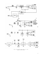
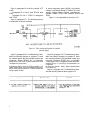
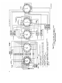
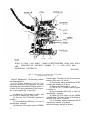
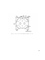
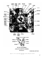
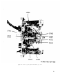
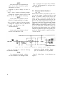
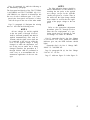
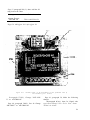
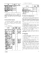
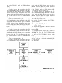
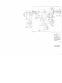
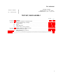
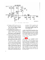
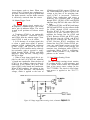
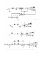
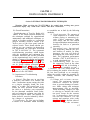
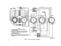
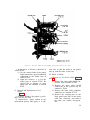
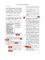
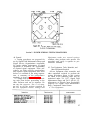
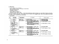
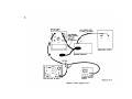
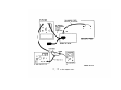
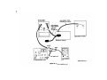
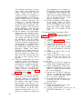
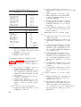
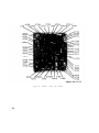
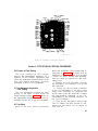
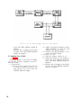
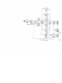
Figure 2. Amplifier, 11.6-mc, schematic diagram.
6. Amplifier, 5.65-Mc
(fig. 3)
The 5.65-mc amplifier is a singlestage if. amplifier which has a gain of
about 15 db. Power, input, and output connections are made to the 5.65-mc amplifier when selector switch S7902 is inposition 12, 15, 16, or 17. The output from the
amplifier is rectified and fed to the Schmitt
trigger circuit.
a. The input signal from the test probe
rf preamplifier is fed to the input attenuation pad consisting of resistors R7701,
R7702, and R7703. The pad reduces the rf
signal level and isolates the 5.65-mc
amplifier from the test probe rf preamplifier.
b. The 5.65-mc amplifier uses transistor Q7701 in a common-base stage
which provides about 15-db gain.
(1) The attenuated signal is coupled to
the emitter of transistor Q7701
through capacitor C7701. The output signal of Q7701 is developed
across a tuned circuit consisting
of coil L7704 and capacitor C7704.
Resistor R7707 reduces the Q of
the tuned circuit to obtain the
proper bandwidth.
(2) Resistors R7705 and R7706 form a
voltage divider which provides the
fixed-biasing portion of emitterbase bias for Q7701. Resistor
R7704 establishes the self-biasing
5