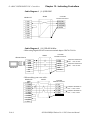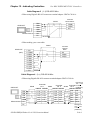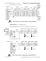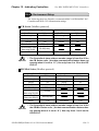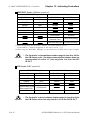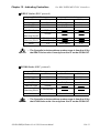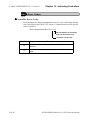
1
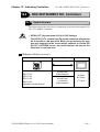
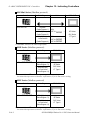
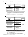
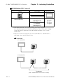
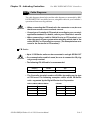
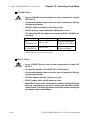
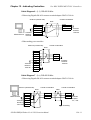
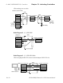
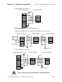
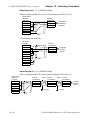
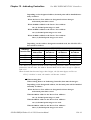
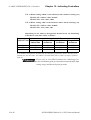
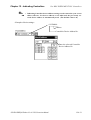
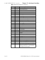
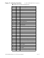
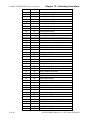
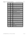
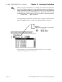
PLC CONNECTION MANUAL
ADDITIONAL MANUAL
RKC Instrument Inc.
CB/REX-F/LE100 Series
(RKC protocol)
Reading the Device/PLC Connection Manual
This additional manual provides connection information for the RKC Instrument Inc.
CB, REX-F or LE100 Series (RKC protocol) models, and is a supplement to the LT
Editor and GP-PRO/PBIII for Windows Device/PLC Connection Manual.
Please refer to this data when connecting a RKC Instrument Inc. CB, REX-F or LE100
Series (RKC protocol) unit.
For information concerning general type PLC connections and this document’s documentation conventions, please refer to your Device/PLC Connection manual.
When connecting a Factory Gateway unit, please substitute the words “Factory Gateway” for this document’s “LT/GLC/GP”.
The information in this document will be included in the next version of the Device/PLC
Connection manual. Therefore, please consider this a provisional document.
Installation
This CD-ROM includes all the driver files required by the LT/GLC/GP to communicate
with a CB, REX-F or LE100 Series (RKC protocol). This document assumes that one
or more of the following software applications are already installed on your PC. Please
note that if more than one of these applications are installed, the screen and data transfer
files included in this CD-ROM must be installed in each of those applications.
For information about the installation of the software, refer to that software's Operation
Manual.
Software Applications
• LT Editor Ver.1.0 or later
• GP-PRO/PBIII for Windows Ver.5.0 or later
• Pro-server with Pro-Studio for Windows Ver.3.0 or later*1
1) Confirm that the Screen Editor software is installed on your hard drive.
2) Double-click on the “cb_rkc.exe” file contained in the CD-ROM.
3) Once the set up program starts, follow the instructions given in the installation program.
When using the CB, REX-F or LE100 Series (RKC protocol), select [RKC CB/
REX-F/LE100(RKC)] for the " PLC Type" .
When using GP-PRO/PBIII for Windows Ver.6.0 or later, click on the Device/PLC
area’s [other] selection and then click on [RKC CB/REX-F/LE100(RKC)].
*1 When using the Factory Gateway unit, GP-Web Ver. 1.0 or later, or GP-Viewer Ver.
1.0 or later, be sure to select the Pro-Server with Pro-Studio for Windows folder as
the “Destination Folder”.
Chapter 12 - Indicating Controllers
12.4
12.4 RKC INSTRUMENT INC. Controllers
RKC INSTRUMENT INC. Controllers
12.4.1
System Structure
The following describes the system configuration used when connecting the GP/
GLC/LT to an RKC Controller.
!
Important
• GP/GLC/LT’s System Area (LS0 to LS19) Settings
The GP/GLC/LT’s system area (20 words) cannot be allocated to
the Controller’s own data area. When you are entering the system area settings via the screen editor software or via the GP/
GLC/LT’s OFFLINE screen, be careful that you do not use the
Controller’s own data area.
CB Series (Modbus protocol)
Controller
CB100 Z-1021
CB400 Z-1021
CB500 Z-1021
CB700 Z-1021
CB900 Z-1021
(Applicable for Modbus Protocol)
GP-PRO/PBIII for Windows Ver. 6.1 PLC Connection Manual
Cable Diagram
RS-422(2-wire)
(Cable Diagram 3)
RS-422(2-wire)
1:n connection
(Cable Diagram 5)
GP/GLC/LT
GP Series
GLC Series
LT Type H
12-4-1
Chapter 12 - Indicating Controllers
12.4 RKC INSTRUMENT INC. Controllers
SR-Mini Series (Modbus protocol)
Controller
H-PCP-A Z-1021
*1
Cable Diagram
RS-232C
(Cable Diagram 1)
RS-422(4-wire)
(Cable Diagram 2)
RS-422(4-wire)
1:n Connection
(Cable Diagram 4)
Cables
GP/GLC/LT
RKC's
W-BF-01-
*1
RKC's
W-BF-01W-BF-02-
GP Series
GLC Series
LT Type H
*1
indicates the cable length (mm).
SRX Series (Modbus protocol)
Controller
X-TIO-A-
-
Cable Diagram
GP/GLC/LT
*
RS-422(4-wire)
GP Series
(Cable Diagram 11)
GLC Series
RS-422(4-wire)
LT Type H
1:n Connection
(Cable Diagram 12)
*1 The model data " " will vary depending on the type of option.
For detailed temperature Controller information, refer to that unit's catalog.
SRV Series (Modbus protocol)
Controller
V-TIO-A-
GP/GLC/LT
RS-422(4-wire)
GP Series
(Cable Diagram 11)
GLC Series
RS-422(4-wire)
LT Type H
1:n Connection
(Cable Diagram 12)
*1 The model data " " will vary depending on the type of option.
For detailed temperature Controller information, refer to that unit's catalog.
12-4-2
-
Cable Diagram
*
GP-PRO/PBIII for Windows Ver. 6.1 PLC Connection Manual
Chapter 12 - Indicating Controllers
12.4 RKC INSTRUMENT INC. Controllers
CB Series (RKC protocol)
Controller *1
CB100
CB400
CB500
CB700
CB900
-
*
*
*
*
*
Cable Diagram
-5
-5
-5
-5
-5
*1 The model data "
/
/
/
/
/
RS-422(2-wire)
(Cable Diagram 6)
RS-422(2-wire)
1:n Connection
(Cable Diagram 7)
GP/GLC/LT
*2
GP Series
GLC Series
LT Type H
" will vary depending on the type of option.
For detailed temperature Controller information, refer to that unit's catalog.
Units that have an option of serial data transfer will have a "5" in their
model code.
*2 This unit can be used with GP-377 Series, GP77R Series, GP2000 Series,
GLC2000 Series, and LT TypeC Units.
REX-F Series (RKC protocol)
Controller *1
Cable Diagram
F400
F700
F900
F400
F700
F900
-
*
*
*
*
*
*
-
-1
-1
-1
-4
-4
-4
F400
F700
F900
-
*
*
*
-
-4
-4
-4
*1 The model data "
GP/GLC/LT
*2
RS-232C
(Cable Diagram 8)
RS-422(4-wire)
(Cable Diagram 9)
RS-422(4-wire)
1:n Connection
(Cable Diagram 10)
GP Series
GLC Series
LT Type H
RS-422(2-wire)
(Cable Diagram 6)
RS-422(2-wire)
1:n Connection
(Cable Diagram 7)
" will vary depending on the type of option.
For detailed temperature Controller information, refer to that unit's catalog.
Serial data transfer option types use a "1" for RS-232C, "4" for RS-422 - 4
wire, and "5" for RS-422 - 2 wire.
*2 This unit can be used with GP-377 Series, GP77R Series, GP2000 Series,
GLC2000 Series, and LT TypeC Units.
GP-PRO/PBIII for Windows Ver. 6.1 PLC Connection Manual
12-4-3
Chapter 12 - Indicating Controllers
12.4 RKC INSTRUMENT INC. Controllers
LE-100 Series (RKC protocol)
Controller *1
LE100-
* 5
-
Cable Diagram
GP/GLC/LT *2
RS-422(2-wire)
(Cable Diagram 6)
RS-422(2-wire)
1:n Connection
(Cable Diagram 7)
GP Series
GLC Series
LT Type H
*1 The model data " " will vary depending on the type of option.
For detailed temperature Controller information, refer to that unit's catalog.
Units that have an option of serial data transfer will have a "5" in their
model code.
*2 This unit can be used with GP-377 Series, GP77R Series, GP2000 Series,
GLC2000 Series, and LT TypeC Units.
Connections
•1:1 connection
•1:n connection
31 units max.
(Max. with SR-Mini Series units is 16 units)
12-4-4
GP-PRO/PBIII for Windows Ver. 6.1 PLC Connection Manual
Chapter 12 - Indicating Controllers
12.4.2
12.4 RKC INSTRUMENT INC. Controllers
Cable Diagrams
The cable diagrams shown below and the cable diagrams recommended by RKC
INSTRUMENT INC. may differ, however, using these cables for your Controller’s
operations will not cause any problems.
!
Important
• When connecting the FG terminal to the connector cover, be sure
that the connector cover conducts current.
• Ground your Controller's FG terminal according to your country's
applicable standard. For details, refer to your Controller’s manual.
• When connecting a cable’s Shield line to an FG terminal, consider the needs of your system when deciding which side of the
cable (GP/GLC or Controller) to connect. (The example below connects to the Controller’s FG terminal.)
CB Series
!
Important
• Up to 31 CB Series units can be connected to a single GP/GLC/LT.
• If a communications cable is used, be sure to connect its SG (signal ground) terminal.
• The following RS-422 cable is recommended.
Company
Hirakawa Densen
Item No.
2207-510-008
Type
CO-HC-ESV-3P X 7/0.2
• The Controller terminal number will differ depending on the type
of CPU used. The following examples reflect all the CB Series
units supported by the Digital Electronics Corporation.
<CB100,CB400,CB500,CB900>
<CB700>
Terminal No.
Signal Name
Terminal No.
Signal Name
13
SG
7
SG
14
T/R(A)
8
T/R(A)
15
T/R(B)
9
T/R(B)
GP-PRO/PBIII for Windows Ver. 6.1 PLC Connection Manual
12-4-5
12.4 RKC INSTRUMENT INC. Controllers
Chapter 12 - Indicating Controllers
SR-Mini Series
!
Important
• Up to 16 SR-Mini Series modules can be connected to a single
GP/GLC/LT.
• If a communications cable is used, be sure to connect its SG (signal ground) terminal.
• RS-232C cables should be 15 meters or less.
• RS-422 (2-wire) cables should be 500 meters or less.
• The following RS-422 cables are recommended for SR-Mini Series units.
Company
Type
Comments
RKC
W-BF-01- XXXX *1
INSTRUMENT INC.
Used when connecting an
SR-Mini to a LT/GLC/GLC
RKC
W-BF-02- XXXX *1
INSTRUMENT INC.
Used when connecting an
SR-Min to an SR-Mini
*1 XXXX indicates the cable length (mm).
REX-F Series
!
Important
• Up to 31 REX-F Series units can be connected to a single GP/
GLC/LT.
• Connect the shield to the GP/GLC/LT's FG terminal.
• If a communications cable is used, be sure to connect its SG (signal ground) terminal.
• RS-232C cables must be 15 meters or less.
• RS-422 cables must be 600 meters or less.
• With REX-F Series units, the terminal numbers and signal names
will vary, depending on the unit's model type and data transfer
method used. The following tables show the possible model type
and signal name combinations.
12-4-6
GP-PRO/PBIII for Windows Ver. 6.1 PLC Connection Manual
Chapter 12 - Indicating Controllers
12.4 RKC INSTRUMENT INC. Controllers
RS-232C Connections
Terminal No.
F400
12
13
14
F700
16
17
18
F900
26
27
28
Signal Name
SG
SD
RD
RS-422 (2-wire) Connections
Terminal No.
F400
12
13
14
F700
16
17
18
F900
26
27
28
Signal Name
SG
T/R(A)
T/R(B)
RS-422 (4-wire) Connections
Terminal No.
F400
12
13
14
15
16
F700
16
17
18
19
20
F900
26
27
28
29
30
Signal Name
SG
T(A)
T(B)
R(A)
R(B)
LE100 Series
!
Important
• Up to 31 LE100 Series units can be connected to a single GP/
GLC/LT.
• Connect the shield to the GP/GLC/LT's FG terminal.
• If a communications cable is used, be sure to connect its SG
(signal ground) terminal.
• RS-422 cables must be 600 meters or less.
• LE100 Series data transfer signal names are as follows:
Terminal No. Signal Name
1
T/R(A)
2
T/R(B)
3
SG
GP-PRO/PBIII for Windows Ver. 6.1 PLC Connection Manual
12-4-7
12.4 RKC INSTRUMENT INC. Controllers
Chapter 12 - Indicating Controllers
Cable Diagram 1 (1:1) RS-232C
GP/GLC/LT
Shield
Controller
Modular Connector
2 SD(TXD)
4 RD(RXD)
3 SG(GND)
6 Shield
2 SD
3 RD
4 RS
5 CS
6 NC
8 CD
20 ER
7 SG
1 FG
Cable Diagram 2 (1:1) RS-422 4-Wire
<When using Digital's RS-422 connector terminal adapter GP070-CN10-0>
Shield
GP070-CN10-0
GP/GLC/LT
Controller
Modular Connector
4 T(B)
5 T(A)
2 R(B)
1 R(A)
3 SG
6 Shield
RDA
RDB
SDA
SDB
TERM
SG
FG
Collective Resistance
120Ω +10% or less
Collective Resistance
120Ω +10% or less
<When making your own cable>
GP/GLC/LT
(25P)
7 SG
9 TRMX
10 RDA
16 RDB
11 SDA
15 SDB
18 CSB
19 ERB
21 CSA
22 ERA
1 FG
12-4-8
Shield
Controller
Modular Connector
3 SG
4 T(B)
5 T(A)
2 R(B)
1 R(A)
6 Shield
Collective Resistance
120Ω +10% or less
Collective Resistance
120Ω +10% or less
GP-PRO/PBIII for Windows Ver. 6.1 PLC Connection Manual
Chapter 12 - Indicating Controllers
12.4 RKC INSTRUMENT INC. Controllers
Cable Diagram 3 (1:1) RS-422 2-Wire
<When using Digital's RS-422 connector terminal adapter GP070-CN10-0>
Controller
Terminal Block
Shield
GP/GLC/LT
GP070-CN10-0
RDA
RDB
SDA
SDB
TERM
SG
FG
T/R(B)
T/R(A)
SG
<When making your own cable>
Shield
GP/GLC/LT
(25P)
Controller
Terminal
Block
7 SG
9 TRMX
10 RDA
16 RDB
11 SDA
15 SDB
18 CSB
19 ERB
21 CSA
22 ERA
1 FG
SG
T/R(B)
T/R(A)
Cable Diagram 4 (1:n) RS-422 4-Wire
<When using Digital's RS-422 connector terminal adapter GP070-CN10-0>
GP/GLC/LT
RDA
RDB
SDA
SDB
TERM
GP070-CN10-0 SG
FG
Shield
Resistance
120Ω +10%
Controller or less
Shield
No. n (Collective)
Controller
Controller
Shield
No. 1
No. 2
COM.PORT1 COM.PORT2
COM.PORT1 COM.PORT2
4 T(B)
4 T(B)
4 T(B)
COM.PORT1 COM.PORT2
4 T(B)
4 T(B)
4 T(B)
5 T(A)
5 T(A)
5 T(A)
5 T(A)
5 T(A)
5 T(A)
3 R(B)
3 R(B)
3 R(B)
3 R(B)
3 R(B)
3 R(B)
2 R(A)
2 R(A)
2 R(A)
2 R(A)
2 R(A)
2 R(A)
3 SG
3 SG
3 SG
3 SG
3 SG
3 SG
6 Shield 6 Shield
GP-PRO/PBIII for Windows Ver. 6.1 PLC Connection Manual
6 Shield 6 Shield
6 Shield 6 Shield
Resistance
120Ω +10%
or less
(Collective)
12-4-9
Chapter 12 - Indicating Controllers
12.4 RKC INSTRUMENT INC. Controllers
Collective
Resistance
120Ω +10%
Controller or less
No. n (Collective)
<When making your own cable>
GP/GLC/LT
(25P)
Shield
7 SG
Controller
Controller
Shield
Shield
No. 1
No. 2
COM.PORT1 COM.PORT2
COM.PORT1 COM.PORT2
COM.PORT1 COM.PORT2
9 TRMX
3 SG
3 SG
3 SG
3 SG
3 SG
3 SG
10 RDA
4 T(B)
4 T(B)
4 T(B)
4 T(B)
4 T(B)
4 T(B)
16 RDB
5 T(A)
5 T(A)
5 T(A)
5 T(A)
5 T(A)
5 T(A)
11 SDA
2 R(B)
2 R(B)
2 R(B)
2 R(B)
2 R(B)
2 R(B)
15 SDB
1 R(A)
1 R(A)
1 R(A)
1 R(A)
1 R(A)
1 R(A)
18 CSB
6 Shield 6 Shield
6 Shield
6 Shield
6 Shield
6 Shield
Collective
Resistance
120Ω +10%
or less
(Collective)
19 ERB
21 CSA
22 ERA
1 FG
!
• Up to 16 units can be connected to a single GP/GLC/LT.
Important
Cable Diagram 5 (1:n) RS-422 2-Wire
<When using Digital's RS-422 connector terminal adapter GP070-CN10-0>
GP/GLC/LT
Shield
GP070-CN10-0
RDA
RDB
SDA
SDB
TERM
SG
FG
Shield
Controller Shield Controller
No. 1
No. 2
Controller
No. n
T/R(B)
T/R(A)
T/R(B)
T/R(B)
T/R(A)
T/R(A)
SG
SG
SG
Grounding
Grounding
<When making your own cable>
GP/GLC/LT (25P)
7 SG
9 TRMX
10 RDA
Shield
Controller Shield
No. 1
SG
T/R(B)
T/R(A)
Controller Shield
No. 2
SG
T/R(B)
T/R(A)
Controller
No. n
SG
T/R(B)
T/R(A)
16 RDB
11 SDA
15 SDB
18 CSB
Grounding
Grounding
19 ERB
21 CSA
22 ERA
1 FG
!
• Up to 31 units can be connected to a single GP/GLC/LT.
Important
12-4-10
GP-PRO/PBIII for Windows Ver. 6.1 PLC Connection Manual
Chapter 12 - Indicating Controllers
12.4 RKC INSTRUMENT INC. Controllers
Cable Diagram 6 (1:1) RS-422 2-Wire
<When using Digital's RS-422 connector terminal adapter GP070-CN10-0>
GP/GLC/LT(Dsub25P male)
Controller Terminal Block
Shield
GP070-CN10-0
Termination
Resistance
120Ω1/2W
RDA
RDB
SDA
SDB
SG
FG
T/R(B)
T/R(A)
SG
Termination
Resistance
120Ω1/2W
<When making your own cable>
GP/GLC/LT(Dsub25P male)
Controller Terminal Block
Shield
Termination
Resistance
120Ω1/2W
1 FG
7 SG
9 TRMX
10 RDA
16 RDB
11 SDA
15 SDB
18 CSB
19 ERB
21 CSA
22 ERA
SG
T/R(B)
T/R(A)
Termination
Resistance
120Ω1/2W
Cable Diagram 7 (1:n) RS-422 2-Wire
<When using Digital's RS-422 connector terminal adapter GP070-CN10-0>
GP/GLC/LT(Dsub25P male)
Controller Terminal Block
Shield
GP070-CN10-0
Termination
Resistance
120Ω 1/2W
RDA
RDB
SDA
SDB
TERM
SG
FG
Controller Terminal Block
Shield
T/R(B)
T/R(A)
SG
T/R(B)
T/R(A)
SG
Termination
Resistance
120Ω 1/2W
Grounding
GP-PRO/PBIII for Windows Ver. 6.1 PLC Connection Manual
12-4-11
Chapter 12 - Indicating Controllers
12.4 RKC INSTRUMENT INC. Controllers
<When making your own cable>
GP/GLC/LT(Dsub25P male)
Shield
1 FG
7 SG
9 TRMX
10 RDA
16 RDB
11 SDA
15 SDB
Termination 18 CSB
Resistance 19 ERB
120Ω 1/2W 21 CSA
22 ERA
Shield
Controller Terminal Block
SG
T/R(B)
T/R(A)
Controller Terminal Block
SG
T/R(B)
T/R(A)
Termination
Resistance
120Ω 1/2W
Grounding
Cable Diagram 8 (1:1) RS-232C
GP/GLC/LT
(Dsub25P male)
1 FG
2 SD
3 RD
4 RS
5 CS
6 NC
7 SG
20 ER
Shield
Controller Terminal Block
RD
SD
SG
Cable Diagram 9 (1:1) RS-422 4-Wire
<When using Digital's RS-422 connector terminal adapter GP070-CN10-0>
Shield
GP/GLC/LT(Dsub25P male)
RDA
RDB
SDA
SDB
SG
FG
GP070-CN10-0
12-4-12
Controller Terminal Block
T (B)
T (A)
R (B)
R (A)
SG
GP-PRO/PBIII for Windows Ver. 6.1 PLC Connection Manual
Chapter 12 - Indicating Controllers
12.4 RKC INSTRUMENT INC. Controllers
<When making your own cable>
GP/GLC/LT(Dsub25P male)
Controller Terminal Block
Shield
1 FG
7 SG
9 TRMX
10 RDA
16 RDB
11 SDA
15 SDB
18 CSB
19 ERB
21 CSA
22 ERA
SG
T (B)
T (A)
R (B)
R (A)
Cable Diagram 10 (1:n) RS-422 4-Wire
<When using Digital's RS-422 connector terminal adapter GP070-CN10-0>
GP/GLC/LT(Dsub25P male)
Controller Terminal Block
Shield
GP070-CN10-0
Controller Terminal Block
Shield
RDA
RDB
SDA
SDB
TERM
SG
FG
T (B)
T (A)
R (B)
R (A)
SG
T (B)
T (A)
R (B)
R (A)
SG
Grounding
<When making your own cable>
GP/GLC/LT(Dsub25P male)
Controller Terminal Block
Controller Terminal Block
Shield
1 FG
7 SG
9 TRMX
10 RDA
16 RDB
11 SDA
15 SDB
18 CSB
19 ERB
21 CSA
22 ERA
!
Shield
SG
T (B)
T (A)
R (B)
R (A)
SG
T (B)
T (A)
R (B)
R (A)
Grounding
• Up to 31 units can be connected to a single GP/GLC/LT.
Important
GP-PRO/PBIII for Windows Ver. 6.1 PLC Connection Manual
12-4-13
12.4 RKC INSTRUMENT INC. Controllers
Chapter 12 - Indicating Controllers
Cable Diagram 11 (1:1) RS-422 4-Wire
<When using Digital's RS-422 connector terminal adapter GP070-CN10-0>
GP070-CN10-0
GP/GLC/LT
(25p male)
RDA
RDB
SDA
SDB
TERM
SG
FG
Controller
Terminal block
T/R(B)
T/R(A)
SG
Termination
Resistance
1/2W100Ω
Shield
<When making your own cable>
GP/GLC/LT
(25p male)
7 SG
9 TRMX
10 RDA
16 RDB
11 SDA
15 SDB
18 CSB
19 ERB
21 CSA
22 ERA
1 FG
Controller
Terminal Block
SG
T/R(B)
T/R(A)
Termination
Resistance
1/2W100Ω
Shield
Cable Diagram 12 (1:n) RS-422 4-Wire
<When using Digital's RS-422 connector terminal adapter GP070-CN10-0>
GP070-CN10-0
GP/GLC/LT
(25p male)
RDA
RDB
SDA
SDB
TERM
SG
FG
Controller
Terminal Block
T/R(B)
T/R(A)
SG
Shield
Controller
Terminal Block
T/R(B)
T/R(A)
SG
Grounding
Shield
Controller
Terminal Block
T/R(B)
T/R(A)
SG
Termination
Resistance
1/2W100Ω
Grounding
Shield
12-4-14
GP-PRO/PBIII for Windows Ver. 6.1 PLC Connection Manual
Chapter 12 - Indicating Controllers
12.4 RKC INSTRUMENT INC. Controllers
<When making your own cable>
GP/GLC/LT
(25p male)
7 SG
9 TRMX
10 RDA
16 RDB
11 SDA
15 SDB
18 CSB
19 ERB
21 CSA
22 ERA
1 FG
Controller
Terminal Block
SG
T/R(B)
T/R(A)
Shield
Controller
Terminal Block
SG
T/R(B)
T/R(A)
Grounding
Shield
Controller
Terminal Block
SG
T/R(B)
T/R(A)
Termination
Resistance
1/2W100Ω
Grounding
Shield
!
• Up to 31 units can be connected to a single GP/GLC/LT.
Important
GP-PRO/PBIII for Windows Ver. 6.1 PLC Connection Manual
12-4-15
Chapter 12 - Indicating Controllers
12.4 RKC INSTRUMENT INC. Controllers
12.4.3
Supported Devices
The following list shows the range of devices supported by the GP/GLC/LT.
CB Series / SR-Mini Series (Modbus protocol)
Device
Data
!
Bit Address
0000 ~ 02EEF
Word Address
0000 ~ 02EE
Comments
L/H
• GP/GLC/LT’s System Area (LS0 to LS19) Settings
Important
The GP/GLC/LT’s system area (20 words) cannot be allocated to
the Controller’s own data area. When you are entering the system area settings via the screen editor software or via the GP/
GLC/LT’s OFFLINE screen, be careful that you do not use the
Controller’s own data area.
• The data communication feature will not operate when the slave
address No. is set to “0”. ( The default value is 0.)
Note:
• Indicating Controller Slave Address settings can be entered in your screen
editor software. If a station number is not indicated, the previously entered station number is automatically used. (The default value is 1.)
E.g. When entering Device Address 02EE
Enter the Device Name “...”, and the Word Address “02EE”.
01 ... 02EE
Word Address
Device Name
Controller’s Slave Address No.
01/02EE
Address
Enter the selected
Controller Slave
Address No.
Controller’s
Slave Address No.
12-4-16
GP-PRO/PBIII for Windows Ver. 6.1 PLC Connection Manual
Chapter 12 - Indicating Controllers
12.4 RKC INSTRUMENT INC. Controllers
SRX Series
Device
Bit Address
Word Address
000000~3FFF
0000~03FF
04000~07FFF
0400~07FF
08000~0883F
0800~0883
10000~13FFF
1000~13FF
14000~17FFF
1400~17FF
18000~1883F
1800~1883
Bit Address
Word Address
00000~03FFF
0000~03FF
08000~0881F
0800~0881
10000~13FFF
1000~13FF
18000~1881F
1800~1881
Remarks
L/H
SRV Series
Device
!
Important
Remarks
L/H
• GP unit internal processing allocates 1024 words to each
device. For this reason, the following features, which require more than one block, cannot be used. When wishing to use these functions, be sure to set them up so that
they do not exceed one block.
1) Specifying the read area.
2) Specifying an a tag.
3) 2-Way block read/write (Pro-Server, GP-Web etc).
ex. In Pro-Server, it is not possible to perform a blockread of 20 words, starting from “03F9”.
• When a tag that will read controller discontinuous addresses is placed on a screen, the GP unit groups the
addresses and does a block read of these addresses.
When this happens, a “Host Communication” error
(02:02:**) occurs in the GP unit where the discontinuous
addresses could not be read. (These addresses may have
been unusable by the controller.)
To prevent this, specify the screen editor’s [Options | Discontinuous Address Compensation Value] as 1. Also,
specify the read tag’s address interval as 2 words.
GP-PRO/PBIII for Windows Ver. 6.1 PLC Connection Manual
12-4-17
Chapter 12 - Indicating Controllers
12.4 RKC INSTRUMENT INC. Controllers
CB Series / REX-F Series / LE100 Series (RKC protocol)
CB Series
Device
Bit Address
Word Address
CB
CB00000~CB0036F
CB0000~CB0036
Comments
H/L
REX-F Series
Device
Bit Address
REX
Word Address
Comments
REX00000~REX0055F REX0000~REX0055
H/L
LE100 Series
Device
Bit Address
Word Address
LE
LE00000~LE0070F
LE0000~LE0070
!
Important
Note:
Comments
H/L
• GP/GLC/LT’s System Area (LS0 to LS19) Settings
The GP/GLC/LT’s system area (20 words) cannot be allocated to
the Controller’s own data area. When you are entering the system area settings via the screen editor software or via the GP/
GLC/LT’s OFFLINE screen, be careful that you do not use the
Controller’s own data area.
• Indicating Controller identifier data contains data to the right of the decimal point. This decimal point data is handled by the GP/GLC/LT as follows:
When reading out data
Data read out by the Indicating Controller is handled as integer data.
EX.
With a value of 100.0:
Indicating Controller: 100.0
GP/GLC/LT:
1000
When displaying decimal point data in a numeric display, use the [Display
Data Format] area's [Decimal Places] setting. In this example, only the
first decimal place is used, so this setting should be "1". Now, the data will
be handled correctly.
EX.
With a value of 100.0:
Indicating Controller: 100.0
GP/GLC/LT:
12-4-18
100.0
GP-PRO/PBIII for Windows Ver. 6.1 PLC Connection Manual
Chapter 12 - Indicating Controllers
12.4 RKC INSTRUMENT INC. Controllers
Depending on the designated address, decimal point will be handled internally as follows:
When the Device List Address is designated with no changes:
no decimal point data is used
When 0x1000 is added to the Device List Address:
one (1) decimal point integer is used
When 0x2000 is added to the Device List Address:
two (2) decimal point integers are used
When 0x3000 is added to the Device List Address:
three (3) decimal point integers are used
Depending on the Address designation method used, the GP/GLC/LT's
data will be as follows:
Indicating
Controller Data
123
123.4
12.34
1.234
No change to
Address data
123
123
12
1
GP/GLC/LT Data
Adding 0x1000 to Adding 0x2000 to Adding 0x3000 to
the Address
the Address
the Address
1230
12300
23000
1234
12340
23400
123
1234
12340
12
123
1234
If the address designation method and the Indicating Controller data's decimal point
position are not the same, the address' decimal data will be either cut off or replaced
with a "0".
When decimal data becomes larger than 5 digits, the left-most digit(s) will be cut.
EX. If "1122334" is used, the number will become "22334".
When writing data
When writing data to an Indicating Controller, data must be integers.
Depending on the designated address, the decimal point will be handled
internally as follows:
When the Device List Address is designated with no changes:
no decimal point data is used
When 0x1000 is added to the Device List Address:
one (1) decimal point integer is used
When 0x2000 is added to the Device List Address:
two (2) decimal point integers are used
When 0x3000 is added to the Device List Address:
three (3) decimal point integers are used
GP-PRO/PBIII for Windows Ver. 6.1 PLC Connection Manual
12-4-19
12.4 RKC INSTRUMENT INC. Controllers
Chapter 12 - Indicating Controllers
EX. 1) When writing "100.0" to the CB Series unit's Alarm 1 Setting (A1)
GP/GLC/LT's address value: 0x1007
GP/GLC/LT's write value: 1000
EX. 2) When writing "100" to the CB Series unit's Alarm 1 Setting (A1)
GP/GLC/LT's address value: 0x0007
GP/GLC/LT's write value: 100
Depending on the Address designation method used, the Indicating
Controller's write data will be as follows:
GP/GLC/LT Data
1
123
1234
No change to
Address data
1
123
1234
Indicating Controller Data
Adding 0x1000 to Adding 0x2000 to Adding 0x3000 to
the Address
the Address
the Address
0.1
0.01
0.001
12.3
1.23
0.123
123.4
12.34
1.234
If the address designation method and the Indicating Controller data's decimal point
position are not the same, the address' decimal data will be either cut off or replaced
with "0".
Please refer to your RKC Instrument Inc. Indicating Controller installation guide for information about identifier data
setting ranges and decimal point positions.
12-4-20
GP-PRO/PBIII for Windows Ver. 6.1 PLC Connection Manual
Chapter 12 - Indicating Controllers
Note:
12.4 RKC INSTRUMENT INC. Controllers
• Indicating Controller device address settings can be entered in your screen
editor software. If a device address is not indicated, the previously entered device address is automatically used. (The default value is 0.)
<Example of device settings>
01/CB0000
Address
Controller's Device Address No.
Enter the selected Controller
Device Address No.
GP-PRO/PBIII for Windows Ver. 6.1 PLC Connection Manual
12-4-21
12.4 RKC INSTRUMENT INC. Controllers
Chapter 12 - Indicating Controllers
Communication identifier list (CB Series)
12-4-22
Address
00
01
02
03
04
05
06
07
08
09
0A
0B
0C
0D
0E
0F
10
11
12
13
14
15
16
17
18
19
1A
1B
1C
1D
1E
Identifier
M1
M2
M3
AA
AB
B1
S1
A1
A2
A3
A4
A5
A6
G1
G2
P1
I1
D1
W1
T0
P2
V1
T1
PB
LK
RS
ER
IO
IP
XI
XQ
1F
LV
Description
Measured value (PV)
Current transformer input 1
Current transformer input 2
Alarm 1 status
Alarm 2 status
Burnout
Set value (SV)
Alarm 1 setting
Alarm 2 setting
Heater break alarm 1 setting
Heater break alarm 2 setting
Control loop break alarm setting
LBA deadband
Autotuning (AT)
Self-tuning (ST )
Heat-side proportional band
Integral time
Derivative time
Anti-reset windup
Heat-side proportional cycle
Cold-side proportional band
Deadband
Cold-side proportional cycle
PV bias
Set data lock function
RUN/ST OP function
Error code
Initialization mode selection
Setting necessary code [Cod]
Input type selection [SL1]
Engineering unit and cooling type selection [SL2]
Heater break alarm (HBA), control loop break alarm
(LBA),special specification, or control loop break
alarm (LBA) output selection [SL3]
GP-PRO/PBIII for Windows Ver. 6.1 PLC Connection Manual
Chapter 12 - Indicating Controllers
Address
Identifier
20
XA
21
XB
22
CA
23
Z1
24
25
26
27
28
29
2A
2B
2C
Z2
Z3
DH
XC
XV
XW
XU
MH
HA
2D
HB
2E
2F
30
31
32
33
34
35
36
XR
F1
GH
PU
IU
IL
HP
UT
UU
12.4 RKC INSTRUMENT INC. Controllers
Description
First alarm (ALM1) type or First alarm (ALM1) with
hold action selection [SL4]
Second alarm (ALM2) type or Second alarm (ALM2)
with hold action selection [SL5]
Control action type selection [SL6]
Energized/de-energized alarm selection, special
specification selection 1 [SL7]
Special specification selection 2 [SL8]
Special specification selection 3 [SL9]
Option selection [SL10]
SV alarm type selection [SL11]
Setting limiter (high limit) [SLH]
Setting limiter (low limit) [SLL]
Setting the position of decimal point [PGdP]
Differential gap setting of ON/OFF action [oH]
Differential gap setting of first alarm (ALM1) [AH1]
Differential gap setting of second alarm (ALM2)
[AH2]
CT ratio setting [CTr]
Digital filter setting [dF]
Time factor assumed to be safe [STTM]
Factor to calculate proportional band [STPK]
Factor to calculate integral time [STIK]
Integral time limiter [ILIM]
Holding peak ambient temperature [TCJ]
Operating time display unit (Upper digits) [WTH]
Operating time display unit (Lower digits) [WTL]
GP-PRO/PBIII for Windows Ver. 6.1 PLC Connection Manual
12-4-23
12.4 RKC INSTRUMENT INC. Controllers
Chapter 12 - Indicating Controllers
Communication identifier list (REX-F Series)
Address
Identifier
Description
00
01
02
03
04
05
06
07
08
09
0A
0B
0C
0D
0E
0F
10
11
12
13
14
15
16
17
18
19
1A
1B
1C
1D
1E
1F
20
21
22
23
24
25
26
27
28
12-4-24
M1
AA
AB
AC
O1
O2
B1
B2
S2
M2
M3
MS
J1
C1
E1
ZA
G1
RA
SR
ON
S1
A1
A2
P1
I1
D1
CA
P2
V1
HH
PB
F1
DP
RR
RB
F2
OH
OL
OQ
PH
PL
Measued-value (PV) input
First alarm output
Second alarm output
Heater break alarm outut
Manipulated output (Heating-side)
Manipulated output (Cooling-side)
Burnout
Feedback resistance (FBR) input burnout
Remote setting value (RS)
Feedback resistance input value (POS)
Current transformer input value
Set-value (SV) monitoring
Auto/manual transfer
Local/remote transfer
Local/external memory area transfer
Control area No. transfer
PID control/auto-tuning transfer
Local mode/computer mode identification
Operation execution (RUN)/STOP transfer
Manipulated output value (MV)
Set-value (SV)
First alarm setting
Second alarm setting
Proportional band (Heating-side)
Integral time
Derivative time
Control response designation parameter
Cooling-side proportional band
Deadband
Setting change rate limit
PV bias
PV digital filter
PV low input cut-off
RS ratio
RS bias
RS digital filter
Output limit (High limit)
Output limit (Low limit)
Cooling output Min. ON time
Increase in output change rate limit
Decrease in output change rate limit
GP-PRO/PBIII for Windows Ver. 6.1 PLC Connection Manual
Chapter 12 - Indicating Controllers
Address
29
2A
2B
2C
2D
2E
2F
30
31
32
33
34
35
36
Identifier
IV
IW
OE
GB
HA
TD
A3
HB
TG
LA
HV
HW
V2
VH
37
SY
38
39
3A
3B
3C
3D
3E
3F
40
41
42
43
44
45
46
47
48
49
4A
4B
4C
4D
4E
4F
DA
XI
AV
AW
WH
WL
XV
XW
XU
XH
SH
SL
XR
XL
T0
T1
XE
XN
SX
XA
NA
OA
WA
XB
12.4 RKC INSTRUMENT INC. Controllers
Description
Upper ON/OFF action (A) differential gap
Lower ON/OFF action (A) differential gap
Manual output at abnormality
AT bias
First alarm differential gap
First alarm timer setting
Heater break alarm
Second alarm differential gap
Second alarm timer setting
Analog output (AO) Specification selection
Analog output (AO) Scale high limit
Analog output (AO) Scale low limit
Neutral zone
Open/close output differential gap
Action selection at feedback resistance (FBR) input
break
Bar-graph display selection
PV input type selection
Input abnormality determination point (High limit)
Input abnormality determination point (Low limit)
Action selection at input abnormality (High limit)
Action selection at input abnormality (Low limit)
Input programmable range (High limit)
Input programmable range (Low limit)
Decimal-point position selection
Square root extraction selection
Setting limit (High limit)
Setting limit (Low limit)
RS input type selection
SV tracking selection
Proportioning cycle (Heating-side)
Cooling-side proportioning cycle
Direct/reverse action selection
Hot/cold start selection
Start determination point
First alarm Action selection
First alarm Energized/de-energized selection
First alarm Action selection at input abnormality
First alarm Hold action selection
Second alarm Action selection
GP-PRO/PBIII for Windows Ver. 6.1 PLC Connection Manual
12-4-25
12.4 RKC INSTRUMENT INC. Controllers
Address
50
51
52
53
54
55
12-4-26
Identifier
NB
OB
WB
LK
LL
DH
Chapter 12 - Indicating Controllers
Description
Second alarm Energized/de-energized selection
Second alarm Action selection at input abnormality
Second alarm Hold action selection
Set data lock level
Area lock
Operation RUN/STOP display lock
GP-PRO/PBIII for Windows Ver. 6.1 PLC Connection Manual
Chapter 12 - Indicating Controllers
12.4 RKC INSTRUMENT INC. Controllers
Communication identifier list (LE100 Series)
Address
0
1
2
3
4
5
6
7
8
9
0A
0B~0D
0E
0F
10
11
12
13
14
15
16
17
18
19
1A
1B
1C
1D
1E
1F
20
21
22
23
24
25
26
27
Identifier
M1
AA
AB
AC
AD
AE
AF
AG
AH
B1
ER
ID
MS
ML
MH
HP
HQ
MW
MZ
A1
A2
A3
A4
A5
A6
A7
A8
A9
AZ
WT
CW
HR
IR
LK
IS
EC
LU
LT
Description
Measured value (PV)
Output 1 status
Output 2 status
Output 3 status
Output 4 status
Output 5 status
Output 6 status
Output 7 status
Output 8 status
Burnout
Error code
ID data
Specific gravity monitor
Scale low monitor
Scale high monitor
Peak hold monitor
Bottom hold monitor
Number of water processing times monitor
Amount of emptiness correction monitor
Output 1 set value
Output 2 set value
Output 3 set value
Output 4 set value
Output 5 set value
Output 6 set value
Output 7 set value
Output 8 set value
Actual liquid output setting
Emptiness adjustment
Number of water processing times
Initializing the number of water processing times
Hold reset
Interlock release
Set data lock
Default setting
Error release
Decimal point position selection
Number of linearizing table setting
GP-PRO/PBIII for Windows Ver. 6.1 PLC Connection Manual
12-4-27
12.4 RKC INSTRUMENT INC. Controllers
Address
28
29
2A
2B
2C
2D
2E
2F
30
31
32
33
34
35
36
37
38
39
3A
3B
3C
3D
3E
3F
40
41
42
43
44
45
46
47
48
49
4A
4B
4C
4D
4E
4F
50
51
12-4-28
Identifier
L0
L1
L2
L3
L4
L5
L6
L7
L8
L9
LA
F1
XA
DA
QA
NA
HA
TA
XB
DB
QB
NB
HB
TB
XC
DC
QC
NC
HC
TC
XD
DD
QD
ND
HD
TD
XE
DE
QE
NE
HE
TE
Chapter 12 - Indicating Controllers
Description
Linearizing table setting 0
Linearizing table setting 1
Linearizing table setting 2
Linearizing table setting 3
Linearizing table setting 4
Linearizing table setting 5
Linearizing table setting 6
Linearizing table setting 7
Linearizing table setting 8
Linearizing table setting 9
Linearizing table setting 10
Digital filter
Output 1 type selection
Output 1 deviation value setting
Output 1 interlocking function selection
Outut 1 a/b contact selection
Output 1 defferential gap
Output 1 timer setting
Output 2 type selection
Output 2 deviation value setting
Output 2 interlocking function selection
Output 2 a/b contact selection
Output 2 differential gap
Output 2 timer setting
Output 3 type selection
Output 3 deviation value setting
Output 3 interlocking function selection
Output 3 a/b contact selection
Output 3 differential gap
Output 3 timer setting
Output 4 type selection
Output 4 deviation value setting
Output 4 interlocking function selection
Output 4 a/b contact selection
Output 4 differential gap
Output 4 timer setting
Output 5 type selection
Output 5 deviation value setting
Output 5 interlocking function selection
Output 5 a/b contact selection
Output 5 differential gap
Output 5 timer setting
GP-PRO/PBIII for Windows Ver. 6.1 PLC Connection Manual
Chapter 12 - Indicating Controllers
Address
52
53
54
55
56
57
58
59
5A
5B
5C
5D
5E
5F
60
61
62
63
64
65
66
67
68
69
6A
6B
6C
6D
6E
6F
70
71
72
Identifier
XF
DF
QF
NF
HF
TF
XG
DG
QG
NG
HG
TG
XH
DH
QH
NH
HH
TH
HV
HW
EG
SW
XX
SG
J1
J2
J3
J4
UN
SP
SS
DS
MM
12.4 RKC INSTRUMENT INC. Controllers
Description
Output 6 type selection
Output 6 deviation value setting
Output 6 interlocking function selection
Output 6 a/b contact selection
Output 6 differential gap
Output 6 timer setting
Output 7 type selection
Output 7 deviation value setting
Output 7 interlocking function selection
Output 7 a/b contact selection
Output 7 differential gap
Output 7 timer setting
Output 8 type selection
Output 8 deviation value setting
Output 8 interlocking function selection
Output 8 a/b contact selection
Output 8 differential gap
Output 8 timer setting
Monitor output high
Monitor output low
End specific gravity setting
Number of water processing times setting
Scale low
Specific gravity setting
Scale 1 actual liquid setting
Scale 2 actual liquid setting
Correction on the low limit side by actual liquid 2
Correction on the high limit side by actual liquid 2
Unit setting
Specific gravity setting transfer
Specific gravity correction function selection
DI function selection
Volume/level display selection
GP-PRO/PBIII for Windows Ver. 6.1 PLC Connection Manual
12-4-29
12.4 RKC INSTRUMENT INC. Controllers
Note:
Chapter 12 - Indicating Controllers
When you register an identifier as a symbol, you can then select that identifier when setting up addresses. In this additional manual’s CD-ROM is a
sample symbol file of addresses registered for Unit No. 0. This sample file
can be imported using the Symbol Editor. For information on how to use
the Import feature, please refer to your screen editor’s Operation Manual.
- Symbol File
: RKCsymbol.lbe
After importing the symbol file, a pull-down list of registered symbols (identifiers) will appear when you click on the black triangle. (see below)
CB_M1
Identifier
Temperature Controller Series Name
CB
:CB Series
REX
:REX-F Series
LE
:LE100 Series
* When using Sta. No. other than the sample file’s Sta. No. 0, be sure to
change the sample file’s Sta. No. data.
12-4-30
GP-PRO/PBIII for Windows Ver. 6.1 PLC Connection Manual
Chapter 12 - Indicating Controllers
12.4.4
12.4 RKC INSTRUMENT INC. Controllers
Environment Setup
The following table lists Digital's recommended RKC INSTRUMENT INC.
Controller and GP/GLC/LT communication settings.
CB Series (Modbus protocol)
GP/GLC/LT Settings
Controller Settings
Baud Rate
9600bps
Baud Rate
9600bps
Data Length
7bits
Data Length
7bits
Stop Bit
2bits
Stop Bit
2bits
Parity Bit
odd
Parity Bit
odd
Data Flow Control
ER(Fixed)
Communication Format
When using RS-422
RS-422(2-wire)
Unit No.
1~32
Slave Address
1~32
!
Important
• The Controller’s slave address number range is from 0 to 99 for
the CB Series units. ( the data communication feature does not
operate when it is set to “0”.) Use only from 1 to 32 on the GP/
GLC/LT.
SR-Mini Series (Modbus protocol)
GP/GLC/LT Settings
Controller Settings
Baud Rate
9600bps
Baud Rate
9600bps
Data Length
8bits
Data Length
8bits
Stop Bit
1bit
Stop Bit
1bit
Parity Bit
None
Parity Bit
None
Data Flow Control
ER(fixed)
Slave Address
1~16
Communication Format
When using RS-232C
Communication Format
When using RS-422
Unit No.
!
Important
RS-232C
RS-422(4-wire)
1~16
• The Controller’s slave address number range is from 1 to 16 for
the SR-Mini Series units. ( the data communication feature does
not operate when it is set to “0”.) Use only from 1 to 16 on the
GP/GLC/LT.
GP-PRO/PBIII for Windows Ver. 6.1 PLC Connection Manual
12-4-31
Chapter 12 - Indicating Controllers
12.4 RKC INSTRUMENT INC. Controllers
SRX/SRV Series (Modbus protocol)
GP/GLC/LT Settings
Controller Settings
Baud Rate
9600bps
Baud Rate
9600bps
Data Length
8bits
Data Length
8bits (fixed)
Stop Bit
1bits
Parity Bit
None
Parity Bit
None
Data Flow Control
ER(Fixed)
Communication Format
2-wire
Unit No.
1
Address Setting
1 *1
MODBUS
Driver Slection
Communication
Switchover Time
6ms (Factory Setting)
Data Interval delay time 0ms (Factory Setting) *2
*1 When designating the controller’s address, the actual address will be:
actual address = address designated by the rotary switch + [1].
*2 When using the Baud Rate 38400bps, set the Data Intervel delay time to 1ms or higher.
!
Important
• The Controller’s slave address number range is from 0 to 100 for
the CB Series units. ( the data communication feature does not
operate when it is set to “0”.) Use only from 1 to 32 on the GP/
GLC/LT.
CB Series (RKC protocol)
GP/GLC/LT Settings
Baud Rate
9600bps
Baud Rate
9600bps
Data Length
8bits
Data Length
8bits
Stop Bit
1bit
Stop Bit
1bit
Parity Bit
None
Parity Bit
None
Data Flow Control
ER(fixed)
Communication Format
When using RS-422
RS-422(2-wire)
Unit No.
0~31
Device Address
0~31
!
Important
12-4-32
Controller Settings
• The Controller’s device address number range is from 0 to 99 for
the CB Series units. Use only from 0 to 31 on the GP/GLC/LT.
GP-PRO/PBIII for Windows Ver. 6.1 PLC Connection Manual
Chapter 12 - Indicating Controllers
12.4 RKC INSTRUMENT INC. Controllers
REX-F Series (RKC protocol)
GP/GLC/LT Settings
Baud Rate
Data Length
Stop Bit
Parity Bit
Data Flow Control
Communication Format
When using RS-232C
Communication Format
When using RS-422
Unit No.
!
Important
Controller Settings
9600bps
7bits
2bits
odd
ER(Fixed)
Baud Rate
DataLength
Stop Bit
Parity Bit
9600bps
7bits
2bits
odd
Device Address
0~31
RS-232C
RS-422(4-wire)
RS-422(2-wire)
0~31
• The Controller’s device address number range is from 0 to 99 for
the REX-F Series units. Use only from 0 to 31 on the GP/GLC/LT.
LE100 Series (RKC protocol)
GP/GLC/LT Settings
Controller Settings
Baud Rate
9600bps
Baud Rate
9600bps
Data Length
8bits
Data Length
8bits
Stop Bit
1bit
Stop Bit
1bit
Parity Bit
None
Parity Bit
None
Data Flow Control
ER(fixed)
Communication Format
When using RS-422
RS-422(2-wire)
Unit No.
0~31
Device Address
0~31
!
Important
• The Controller’s device address number range is from 0 to 99 for
the LE100 Series units. Use only from 0 to 31 on the GP/GLC/LT.
GP-PRO/PBIII for Windows Ver. 6.1 PLC Connection Manual
12-4-33
12.4 RKC INSTRUMENT INC. Controllers
12.4.5
Chapter 12 - Indicating Controllers
Error Codes
Controller Error Codes
Error messages (Ex. Host communication error (02:**:##) ) are displayed in the
lower left corner of the GP/GLC/LT screen (** stands for an error code specific
to the Controller).
Host Communication Error (02:**:##)
Device Address of Controller
that has caused the error
Controller Error Code
Error Code
04
15
12-4-34
Description
Occurs when a read out is performed from an address that cannot be
read from.
Occurs when writing setting values that are outside of the allowed
range.
GP-PRO/PBIII for Windows Ver. 6.1 PLC Connection Manual
Appendix
A1
Maximum Number of Consecutive PLC Addresses
The following lists the maximum number of consecutive addresses that can be read by
each PLC. Refer to these tables to utilize Block Transfer.
CB/REX-F/LE100 Series (RKC protocol)
Device
Max No. of Consecutive
Addresses
CB
REX
1 Word
LE
GP-PRO/PBIII for Windows Ver.6.0 PLC Connection Manual
Appendix-1
Appendix
A2
Device Codes and Address Codes
Device codes and address codes are used to specify indirect addresses for E-tags and Ktags.
CB Series (RKC protocol)
Device
Word Address
Device Code
Address Code
CB
CB0000~
8000
Word Address
CB1000~
8200
CB2000~
8400
CB3000~
8600
Save as word address value
minus 0x100
Save as word address value
minus 0x200
Save as word address value
minus 0x300
REX-F Series (RKC protocol)
Device
Word Address
Device Code
Address Code
REX
REX0000~
9000
Word Address
REX1000~
9200
REX2000~
9400
REX3000~
9600
Save as word address value
minus 0x100
Save as word address value
minus 0x200
Save as word address value
minus 0x300
LE100 Series (RKC protocol)
Appendix-2
Device
Word Address
Device Code
Address Code
LE
LE0000~
A000
Word Address
LE1000~
A200
LE2000~
A400
LE3000~
A600
Save as word address value
minus 0x100
Save as word address value
minus 0x200
Save as word address value
minus 0x300
GP-PRO/PBIII for Windows Ver.6.0 PLC Connection Manual
Appendix
A3
Address Conversion Table
Refer to the following Address Conversion Table to convert addresses correctly.
: When the selected conversion mode is [Word], both word and bit addresses
are converted. When the [Bit] is selected, only bit addresses are converted.
After Conversion
CB
REX
LE
LS
Before
Conversion
CB
REX
LE
LS
GP-PRO/PBIII for Windows Ver.6.0 PLC Connection Manual
Appendix-3