1
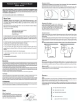
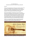
The four-band equalizer / preamp is the brain of the ACOUSTIC
MATRIX PROFESSIONAL system. This low-profile “slider” unit features BASS, TREBLE, MIDRANGE and BRILLIANCE controls as
well as a “set it and forget it” SUB-BASS energy trim control located
on the back of the preamp. This internal trim feature can be used to
adjust the amount of soundhole resonance or “bottom” so that the
THE PREAMP
The incredibly small size and convenient under the saddle design of
the transducer helps preserve the beauty and structural integrity of
your instrument.
The ACOUSTIC MATRIX pickup is made with a unique co-polymer
sensing material available exclusively from Fishman. This material
exhibits a sensitivity and dynamic range that far surpasses all other
known materials.
INSTALLATION BY A QUALIFIED PROFESSIONAL REPAIRMAN IS
STRONGLY RECOMMENDED. FISHMAN TRANSDUCERS WILL
NOT BE RESPONSIBLE FOR ANY DAMAGES TO YOUR INSTRUMENT DUE TO IMPROPER INSTALLATION.
WARNING
If you are new to under saddle piezo installations, a comprehensive
guide, “The Finer Points of Piezo Installation” by Ken Parker, is
available from Fishman.
PIEZO INSTALLATION
If you plan to mix the ACOUSTIC MATRIX with an onboard mini
electret microphone through the Fishman Blender System (routed
through a single stereo instrument cable), you must first install a
Fishman SMART SWITCH. Call Fishman at 978-988-9665 for more
information.
SMART SWITCH
THE TRANSDUCER
Thank you for your purchase of a FISHMAN product. Please read
these instructions carefully. If you have any questions or problems,
contact our PRODUCT INFORMATION LINE at 978-988-9665.
preamp will function at optimum performance levels in guitars of
varying body sizes. Other features include a battery function indicating LED and a PHASE SWITCH.
ACOUSTIC MATRIX PROFESSIONAL
I N S T A L L A T I O N
G U I D E
INSTALLATION BY A QUALIFIED PROFESSIONAL REPAIRMAN IS STRONGLY
RECOMMENDED. FISHMAN TRANSDUCERS WILL NOT BE RESPONSIBLE FOR ANY
DAMAGES THAT MAY RESULT FROM IMPROPER INSTALLATION.
The FISHMAN ACOUSTIC MATRIX PROFESSIONAL is warranted to function for a period of
One (1) Year from the date of purchase. If the unit fails to function properly within the
warranty period, free repair and the option of replacement or refund in the event that
FISHMAN is unable to make repair are FISHMAN’s only obligations. This warranty does not
cover any consequential damages or damage to the unit due to misuse, accident, or neglect.
FISHMAN retains the right to make such determination on the basis of factory inspection.
Products returned to FISHMAN for repair or replacement must be shipped in accordance with
the Return Policy, as follows. This warranty remains valid only if repairs are performed by
FISHMAN. This warranty gives you specific legal rights and you may also have other rights
which may vary from state to state.
ACOUSTIC
MATRIX
PROFESSIONAL
ACTIVE ACOUSTIC GUITAR SYSTEM
RETURN POLICY
To return products to FISHMAN TRANSDUCERS, you must follow these steps...
1. Call FISHMAN TRANSDUCERS at 978-988-9199 for a Return Authorization Number
(“RAN”).
2. Enclose a copy of the original Bill of Sale as evidence of the date of purchase, with the
product in its original packaging and a protective carton or mailer.
3. FISHMAN TRANSDUCERS’ technicians will determine whether the item is covered by warranty or if it instead has been damaged by improper customer installation or other causes
not related to defects in material or workmanship.
WIDE FORMAT:
.125” (3.2 mm) Width
NARROW FORMAT:
.093” (2.3 mm) Width
4. Warranty repairs or replacements will be sent automatically free of charge.
5. If FISHMAN TRANSDUCERS determines the item is not covered by warranty, we will notify
you of the repair or replacement cost and wait for your authorization to proceed.
®
FISHMAN TRANSDUCERS®
340-D Fordham Road Wilmington MA 01887 USA
Phone 978-988-9199 • Fax 978-988-0770
www.fishman.com
009-067-001 2-97
PARTS LIST
TOOLS
•
•
•
•
•
• Caliper
• Router with 1/8" (3 mm)
(or .9375" Plunging Cutter
for Narrow Format)
• 400 Grit Sandpaper or Scraper
• Flex Shaft Tool with 1" (25.4 mm)
Diameter Saw Blade or Router
with 1/4" (6.30 mm) cutter.
• Soldering Iron (30 watt max)
• Rosin Core Solder
• Wire Strippers
• #1 Phillips Screwdriver
• Variable Speed Drill
• Center Punch
• 1/8" Twist Drill
• 15/32" Spade Bit Drill
• 1/2" Open End Wrench
• 3/32" Allen Wrench
•
•
•
•
The ACOUSTIC MATRIX transducer is a multi-layer configuration of
continuous strips of sensing material that are fully EMI shielded.
This continuous strip design allows it to sense the motion of the
entire saddle rather than small sections of it (as is the case with
traditional ceramic based transducers); providing superb string balance.
NOTE: Always handle the pickup with care. Mishandling may result
in ground hum or intermittent signal. Fishman Transducers will not
be responsible for any damages that may occur due to misuse or
poor installation.
LIMITED WARRANTY
PART I - PREPARATION
•
•
•
Slider Bezel
Preamp
Acoustic Matrix Pickup
1/4" Stereo Jack, with hardware
4-40 Screws (4), 3/16" length, with
Star Washers
4-40 Screws (4), 7/16" length
1/4" Aluminum Hex Standoffs (4),
9/16" length
3/16" Brass Hex Jack Screws (4),
1/2" length
(3) Adhesive-backed Plastic
Wire Guides
Preamp Cutout Template
(5) Slider Knobs
Back Plate with Battery Clip
PICKUP DIMENSIONS
WIDE FORMAT
NARROW FORMAT
Width:
.125" (3.2 mm)
Width:
.09375" (2.4 mm)
Height:
.053" (1.35 mm)
Height:
.043" (1.1 mm)
Length:
2.650" (67.3 mm)
Length:
2.650" (67.3 mm)
Sensing Area:
2.670" (67.8 mm)
Sensing Area:
2.670" (67.8 mm)
Max. recommended string spacing:
2.500" (63.5 mm)
Max. recommended string spacing:
2.500" (63.5 mm)
NOTE: The overall length of the Matrix pickup is 2.700" (68.58mm).
We recommend a saddle slot length of at least 2.875" (73mm).
The actual sensing area of the pickup is 2.670" long and can accommodate string spacings of up to 2.500" (63.5 mm). Poor string balance may result with string spacings greater than this.
DO NOT trim the end of the pickups length as ground hum will occur.
Custom pickup lengths are available from Fishman.
COMPENSATED SADDLES
We do not recommend compensating the saddle under the "B" string.
Doing so may twist the saddle and cause uneven pickup response.
PREPARE THE SADDLE SLOT
1. Rout a .125" (3.2 mm) wide saddle slot
for the Acoustic Matrix Wide Format
pickup.
OR
Rout a .09375" (2.3 mm) wide
slot for the Acoustic Matrix
Narrow Format pickup.
2. Be certain that the bottom of the slot is FLAT.
Deepen an existing slot only enough to obtain a clean, flat surface.
LOCATE THE WIRE HOLE
1. Locate the center of the wire hole no less than .100" (2.5 mm) from
the closest string.
2. Mark the location where the wire will enter the saddle slot. Center
the mark between the walls (width) of the slot.
3. Drill a .09375" hole.
4. Clear wood chips and foreign materials from the saddle slot.
5. Carefully insert (do not bend) the pickup.
MECHANICAL FACTORS AFFECTING
PICKUP PERFORMANCE
BREAK ANGLE
There must be an adequate
amount of downbearing pressure on the pickup in order
for it to perform optimally.
The pickup will "see" an acceptable amount of downbearing pressure
when there is a 20° (minimum) break angle across the saddle.
A pickup in a Guitar with less than a 20° break angle will often have
string balance problems as well as poor tone. For such instruments,
an adequate break angle can be realized by "ramping" the string slots
or (in extreme cases) raising the saddle height and resetting the neck
angle.
THE 50/50 RULE
PREPARE THE SADDLE
For adequate coupling between string, saddle and pickup, we recommend that the saddle slot depth (with pickup installed) should equal no
more than 50% of the total height of the saddle.
We recommend synthetic materials such as Micarta or Corian as
excellent saddle materials for the Acoustic Matrix. Organic materials
such as bone or ivory are not as consistent and may result in poor
string balance.
ADJUSTING FOR TOO DEEP A SADDLE SLOT
1. Prepare a .125" wide saddle (.09375" for Narrow Format) The bottom of the saddle must be FLAT.
WARNING
INSTALLATION BY A QUALIFIED PROFESSIONAL REPAIRMAN IS
STRONGLY RECOMMENDED. FISHMAN TRANSDUCERS WILL
NOT BE RESPONSIBLE FOR ANY DAMAGES THAT MAY RESULT
FROM IMPROPER INSTALLATION.
EXCEPTION: Pickups in guitars with a very steep string break angle
(25° or more), will generally perform well, even if the saddle slot depth
measures more than 50% of the total saddle height.
If the slot (with pickup installed) measures more than 50% of the total
saddle height, the pickup performance will often suffer. To correct for
too deep a slot, place a wood shim under the pickup. Determine the
proper thickness of the shim by subtracting 1/2 of the total saddle
height from the slot depth (with pickup installed). Then, remove an
amount of material equal to the thickness of the shim from the bottom
of the saddle.
2. Remove only enough material from the width of the saddle to provide a sliding fit in the slot. To test the fit, the saddle should slide
easily in the slot, but should not fall out when overturned. To maintain your current action, the new saddle must be .053" shorter in
height (.043" for Narrow Format pickups) than your current saddle.
PART I - PREPARATION Cont’d.
PREAMP CUT-OUT
For guitars with non-laminated sides, we strongly recommend gluing a
thin plywood patch inside the guitar before cutting out the cavity. This
will prevent cracking and splintering of the cut-out area during cutting,
and provide adequate structural support for the preamp.
1. Choose the preamp location on the side of the instrument.
Note that the bezel has the ability to conform to most curved surfaces on standard size guitars.
2. Tape the enclosed Cutout Template to the desired location.
Use the flex shaft tool (with 1/2" blade) or the router (with 1/4" cutter) to make the cut-out.
3. Drill the screw mounting holes using the 1/8" drill.
PART II - INSTALLATION
a complete stop before removing it from the hole.
SOLDER THE WIRE CONNECTIONS
1. Insert the pickup in the saddle slot then strip and tin
the wire ends.
2. Solder the "hot" wire from
the pickup (inner conductor)
to the pad marked "IN" on
the preamp circuit board.
Solder the "ground" wire
from the pickup (shield) to
the pad marked "GND" on
the preamp circuit board.
3. Strip and tin the wire ends
of the preamp output cable.
Solder the RED wire to TIP,
the BLACK wire to RING
and the ground wire to the
SLEEVE of the 1/4" jack.
FASTEN THE JACK IN THE ENDPIN HOLE
PREPARE THE ENDPIN BLOCK
TOOLS
•
•
•
•
Masking Tape
Variable Speed Drill
1/8" Twist Drill
1/2" Open End Wrench
•
•
•
•
X-Acto Fine-toothed Saw
Center Punch
15/32" Spade Bit Drill
3/32" Allen Wrench
The objective of this method is to drill a hole in the endblock, with the
endpin in place. You may remove a loose endpin and refasten it in the
endblock with cyanoacrylate glue before starting this procedure.
Follow this sequence when installing the endpin jack:
1 - Shielding Cap (optional)
2 - First Large Hex Nut
3 - Large Dress Washer
4 - Star Washer
5 - Guitar Endblock
6 - Small Dress Washer
7 - Small Dress Nut
8-
Strap Button
1. Apply masking tape around the endblock area to protect the instrument.
2. Locate an X-Acto saw blade 1/16" away from the body and saw off
the endpin.
3. Centerpunch a guide hole in the center of the trimmed endpin.
4. Drill a 1/8" pilot hole through the endblock.
5. Line up a 15/32" Spade bit in the pilot hole and begin drilling.
Maintain a perpendicular plunge in relation to the instrument. Use
steady (but not heavy) pressure, especially as the drill exits inside
the guitar.
IMPORTANT: To avoid damage to the instrument, let the drill come to
The jack should protrude at least 5/16" and no more than 11/32" outside of the body for proper fit. After fitting the small dress washer and
nut over the end of the jack, insert the 3/32" allen wrench through the
cross drilled hole on the end of the jack. Tighten the nut with the 1/2"
open end wrench while holding the jack in place with the allen wrench.
Thread and hand tighten the the strap button.
NOTE: With the strap button in place, the end of
the jack should protrude slightly to allow proper
plug fit.
MOUNT THE PREAMP
OPERATION
The hardware supplied will accommodate guitars with laminated sides
that are between .100" and .175" thick. If your guitar has sides less
than .100" thick, the slider knobs will not fit in the bezel properly.
To make up the difference, use #4-40 washers to shim the preamp
inside the instrument or contact Fishman for longer standoffs.
1. Fasten the 3/16" brass hex screws and the 1/4" hex standoffs to
the preamp as shown. Note that the mounting holes on the volume
control side of the circuit board are slotted to allow for fitting the
preamp to the curved surface of the guitar side.
2. Temporarily fit the preamp and bezel together on the guitar, with
the standoffs finger tight. Fasten the bezel with the #4-40 1/2"
screws to check the standoff alignment. Align the standoffs if necessary. Remove the preamp from the guitar. Tighten the aligned
standoffs secure.
3. Mount the backplate to the preamp with the 3/16" #4-40 screws.
Install the battery and string up the guitar.
4. Plug the guitar into an amplifier and set all the slider's tone controls to their center positions. On the back of the preamp, there is
a recessed Sub-Bass control which is preset at the factory to full
boost. This can be used to roll-off the amount of “bottom end”
which can cause feedback (especially in larger dreadnought-style
guitars). Turn the trim pot counter clockwise for less bass.
5. Re-install the preamp into the guitar. Be sure that the low battery
LED lines up with the corresponding hole in the bezel.
6. Attach the adhesive backed plastic wire guides to the sides or the
kerfing of the instrument.
7. Insert a 9 Volt Alkaline battery into the battery clip.
IMPORTANT: Although the supplied battery holder should provide
adequate capacity to grip the battery at all times, we strongly recommend removal of the battery when shipping your instrument. FAILURE
TO REMOVE BATTERY COULD RESULT IN DAMAGE TO YOUR
INSTRUMENT. Fishman will not be held responsible for any such damage as a result of shipping or handling.
The output jack of the Acoustic Matrix Professional System is also the
power switch for the battery.
When a cable is first plugged into this jack, the BATT/LOW LED will flash
momentarily to indicate that the power is on.
When the battery power is low, this light will remain lit.
Be sure to unplug the output jack when not in use
to avoid battery drain.
Adjust the volume of the preamp and your amplifier as desired.
Using your ears as a guide, set the PHASE switch for proper phase
relationship with the sound source (amps, monitors, etc.).
This relationship is most audible at louder volumes and will change from
room to room and with your position on stage.
TROUBLESHOOTING
SYMPTOM: Weak string or strings
PROBLEM
SOLUTION
Saddle is too tight/loose in slot
Saddle should have a precise, sliding
fit in the slot
Bottom of saddle is not flat
Flatten bottom of saddle
Bottom of saddle slot is not flat
Rout out saddle slot
Less than adequate
downbearing pressure
Observe the 50/50 rule - In extreme belly up
cases, a neck reset may be necessary
SYMPTOM: Hum
PROBLEM
SOLUTION
Saddle fit is too tight
Sand off side of the side of the saddle
to provide a sliding fit
Pickup tube is torn
Replace the pickup