1
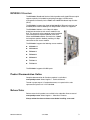
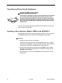
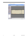
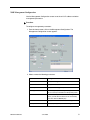
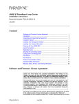
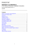
BSX8000-5 Broadband Services Switch Installation Instructions Document Number BSX8-A2-GZ40-20 June 2005 Contents Software and Firmware License Agreement ...................................................... 1 Product Documentation Online .......................................................................... 3 Release Notes ................................................................................................... 3 BSX8000-5 Overview ........................................................................................ 3 Unpacking and Inspecting the Equipment ......................................................... 4 Installing a Micro Interface Module (MIM) in the BSX8000-5 ............................ 4 Installing the BSX8000-5 in a BLC .................................................................... 5 Connect the MIM to the Network ....................................................................... 5 BLC Management .............................................................................................. 6 Web Interface (NMS) ......................................................................................... 6 Command Line Interface (CLI) .......................................................................... 10 LED Indicators ................................................................................................... 13 10/100/1000BaseT Connectors ......................................................................... 14 DB9 to RJ45 Adapter Pinouts ............................................................................ 14 Regulatory Compliance for Class A Equipment ................................................. 15 Warranty, Sales, Service, and Training Information ........................................... 15 Software and Firmware License Agreement ONCE YOU HAVE READ THIS LICENSE AGREEMENT AND AGREE TO ITS TERMS, YOU MAY USE THE SOFTWARE AND/OR FIRMWARE INCORPORATED INTO THE PARADYNE PRODUCT. BY USING THE PARADYNE PRODUCT YOU SHOW YOUR ACCEPTANCE OF THE TERMS OF THIS LICENSE AGREEMENT. IN THE EVENT THAT YOU DO NOT AGREE WITH ANY OF THE TERMS OF THIS LICENSE AGREEMENT, PROMPTLY RETURN THE UNUSED PRODUCT IN ITS ORIGINAL PACKAGING AND YOUR SALES RECEIPT OR INVOICE TO THE LOCATION WHERE YOU OBTAINED THE PARADYNE PRODUCT OR THE LOCATION FROM WHICH IT WAS SHIPPED TO YOU, AS APPLICABLE, AND YOU WILL RECEIVE A REFUND OR CREDIT FOR THE PARADYNE PRODUCT PURCHASED BY YOU. The terms and conditions of this License Agreement (the “Agreement”) will apply to the software and/or firmware (individually or collectively the “Software”) incorporated into the Paradyne product (the “Product”) purchased by you and any derivatives obtained from the BSX8-A2-GZ40-20 June 2005 1 Software, including any copy of either. If you have executed a separate written agreement covering the Software supplied to you under this purchase, such separate written agreement shall govern. Paradyne Corporation (“Paradyne”) grants to you, and you (“Licensee”) agree to accept a personal, non-transferable, non-exclusive, right (without the right to sublicense) to use the Software, solely as it is intended and solely as incorporated in the Product purchased from Paradyne or its authorized distributor or reseller under the following terms and conditions: 1. Ownership: The Software is the sole property of Paradyne and/or its licensors. The Licensee acquires no title, right or interest in the Software other than the license granted under this Agreement. 2. Licensee shall not use the Software in any country other than the country in which the Product was rightfully purchased except upon prior written notice to Paradyne and an agreement in writing to additional terms. 3. The Licensee shall not reverse engineer, decompile or disassemble the Software in whole or in part. 4. The Licensee shall not copy the Software except for a single archival copy. 5. Except for the Product warranty contained in the manual, the Software is provided “AS IS” and in its present state and condition and Paradyne makes no other warranty whatsoever with respect to the Product purchased by you. THIS AGREEMENT EXPRESSLY EXCLUDES ALL OTHER WARRANTIES, WHETHER EXPRESS OR IMPLIED, OR ORAL OR WRITTEN, INCLUDING WITHOUT LIMITATION: a. Any warranty that the Software is error-free, will operate uninterrupted in your operating environment, or is compatible with any equipment or software configurations; and b. ANY AND ALL IMPLIED WARRANTIES, INCLUDING WITHOUT LIMITATION IMPLIED WARRANTIES OF MERCHANTABILITY, FITNESS FOR A PARTICULAR PURPOSE AND NON-INFRINGEMENT. Some states or other jurisdictions do not allow the exclusion of implied warranties on limitations on how long an implied warranty lasts, so the above limitations may not apply to you. This warranty gives you specific legal rights, and you may also have other rights which vary from one state or jurisdiction to another. 6. In no event will Paradyne be liable to Licensee for any consequential, incidental, punitive or special damages, including any lost profits or lost savings, loss of business information or business interruption or other pecuniary loss arising out of the use or inability to use the Software, whether based on contract, tort, warranty or other legal or equitable grounds, even if Paradyne has been advised of the possibility of such damages, or for any claim by any third party. 7. The rights granted under this Agreement may not be assigned, sublicensed or otherwise transferred by the Licensee to any third party without the prior written consent of Paradyne. 8. This Agreement and the license granted under this Agreement shall be terminated in the event of breach by the Licensee of any provisions of this Agreement. 9. Upon such termination, the Licensee shall refrain from any further use of the Software and destroy the original and all copies of the Software in the possession of Licensee together with all documentation and related materials. This Agreement shall be governed by the laws of the State of Florida, without regard to its provisions concerning conflicts of laws. 2 June 2005 BSX8-A2-GZ40-20 BSX8000-5 Overview The BSX8000-5 Broadband Services Switch provides multi-gigabit Ethernet uplink support capability, full-nonblocking switching throughput, and enhanced management functionality for the 4000E and 12000E Broadband Loop Carriers (BLCs). The BSX8000-5 supports four fixed 10/100/1000 RJ45 Ethernet interfaces and one MIM (Micro Interface Module) slot. Multiple MIM varieties are supported. The BSX8000-5 delivers a full 1 Gbps full duplex backplane connection to each access module in the BLC. This ensures that the aggregate access bandwidth cannot exceed the backplane speed of the chassis. When two BSX8000 modules are used in the 12000E, the backplane speed is doubled, providing a 2 Gbps connection to each access module. The BSX8000-5 supports the following access modules: AAM8000-24 AIM24000-48 EIM2000-12 EIM2000-24 SIM2000-24 TIM1500-12 TIM1500-24 The BSX8000-5 supports 576 DSL ports. Product Documentation Online Complete documentation for Paradyne products is available at www.paradyne.com. Select Support → Technical Manuals. To order a paper copy of a Paradyne document, or to speak with a sales representative, please call 1-727-530-2000. Release Notes Release notes for this product are available in the subscriber firmware area of www.paradyne.com. Select Support → Subscriber Firmware. Always review the relevant release notes before installing a new card. BSX8-A2-GZ40-20 June 2005 3 Unpacking and Inspecting the Equipment HANDLING PRECAUTIONS FOR ! STATIC-SENSITIVE DEVICES This product is designed to protect sensitive components from damage due to electrostatic discharge (ESD) during normal operation. When performing installation procedures, however, take proper static control precautions to prevent damage to equipment. If you are not sure of the proper static control precautions, contact your nearest sales or service representative. If there is any visible damage, do not attempt to connect the device. Contact your sales or support representative Installing a Micro Interface Module (MIM) in the BSX8000-5 A MIM provides the upstream network connection for the BLC. Any of Paradyne's available MIM models may be installed on the BSX8000-5 uplink module. Procedure 1. Remove the cover plate from the MIM port. CAUTION: Cover plates should be stored for possible future use. If a MIM is removed from a BSX8000-5, it must be replaced with either another MIM or a cover plate. Do not operate a BSX8000-5 with an open MIM port. 2. Carefully slide the faceplate of the MIM into the BSX8000-5 uplink module faceplate. Ensure that the mounting holes on the MIM are lined up with the BSX8000-5 uplink module. 3. Secure the MIM circuit board to the BSX8000-5 uplink module with the two thumbscrews. 4 June 2005 BSX8-A2-GZ40-20 Installing the BSX8000-5 in a BLC The 12000E is a 14-slot Broadband Loop Carrier (BLC). Slots 1–12 are reserved for access modules (such as the AIM24000-48) and slots U1 and U2 are reserved for uplink modules. Although not required for operational purposes, if redundancy is desired, two BSX8000-5 modules may be installed in the 12000E, in slots U1 and U2. (Note: For redundancy, the two uplink modules in the chassis must be identical models.) The 4000E is a five-slot BLC. Slots 1–4 are reserved for access modules and slot U1 is reserved for a single uplink module. Procedure 1. Align the BSX8000-5 uplink module with the slot module guides of the chosen slot for installation (either slot U1 or U2 on the 12000E or slot U1 on the 4000E). 2. Slide the BSX8000-5 uplink module into the chassis. Do not use excessive force. 3. Tighten the fastening screws on the BSX8000-5 uplink module faceplate. 4. Verify that the PWR (Power) LED on the BSX8000-5 faceplate is illuminated. Connect the MIM to the Network Connect to the core network by using one of the fixed GigE interfaces or by using an interface from the added MIM. See 10/100/1000BaseT Connectors on page 14. MIM-10/100 Plug your Ethernet cable into the RJ45 Ethernet port on the MIM-10/100 faceplate. The MIM-10/100 connects to a router or a PC with a straight-through cable and to a hub or a switch with a crossover cable. Verify the connection: solid illumination of the Lnk (link) LED on the MIM-10/100 faceplate indicates an Ethernet uplink connection has been established. The MIM-10/100 Ethernet port is 10/100 auto-negotiating. NOTE: Configure the remote device with which you are connecting to auto-negotiate (if applicable) prior to establishing your Ethernet connection. MIM100F Plug your Ethernet Fiber Optic Cable into the port on the MIM100F faceplate. MIM-2000F The MIM-2000F is a two-port fiber gigabit Ethernet interface, which connects to the Fast Ethernet Bus of the BLC. This will function but is not recommended for use with the BSX8000-5 Uplink Interface. BSX8-A2-GZ40-20 June 2005 5 MIM-4000F The MIM-4000F is a four-port fiber gigabit Ethernet interface connecting directly to the gigabit Ethernet switch in the BSX8000-5 uplink module. MIM-2E1 or MIM-4E1 Plug your E1 cable into one of the RJ45 E1 ports on the MIM faceplate. The MIM-2E1 or MIM-4E1 connects to an E1 network extender provider unit, or an interface module in another BLC, via a standard E1 line. Verify the connection: the Lnk (link) LED on the MIM faceplate flashes green to indicate a network connection has been established. MIM-2T1 or MIM-4T1 Plug your T1 cable into one of the RJ45 T1 ports on the MIM faceplate. The MIM-2T1 or MIM-4T1 connects to a T1 network extender provider unit, or an interface module in another BLC, via a standard T1 line. Verify the connection: the Lnk (link) LED on the MIM faceplate flashes green to indicate a network connection has been established. BLC Management The BSX8000-5 uplink module provides BLC management capability via the Command Line Interface (CLI), Simple Network Management Protocol (SNMP), and the web-based Network Management System (NMS). Web Interface (NMS) The following are required for use of the NMS: Web Browser – Required for running NMS. Compatible web browsers include, but are not limited to, Microsoft Internet Explorer (version 6.0 or higher) and Netscape Navigator (version 6.0 or higher). NMS is optimized for use with Internet Explorer. Use your browser's default settings when running NMS. JavaScript must be enabled. Screen Resolution – 1024 x 768 pixels is the minimum resolution required for all NMS views to fit within the dimensions of most monitors and laptops. Lower screen resolutions (such as 800 x 600 pixels) may cause NMS screens to exceed the width or height of the screen. To verify screen resolution on a Windows system: — Right click on your desktop — Select Properties — Click the Settings tab — Adjust the Screen Resolution as needed 6 June 2005 BSX8-A2-GZ40-20 Configuring Your Windows PC to Communicate with NMS To communicate with NMS, your PC’s Ethernet interface must be on the same subnet as the BSX8000-5. For example, to configure the IP address under Windows XP: Procedure 1. In the Windows task bar, click on the Start button, and then click on Control Panel. 2. Double-click on the Network Connections icon. 3. In the LAN or High-Speed Internet window, right-click on the icon corresponding to your network interface card (NIC) and select Properties. (Often this icon is labeled Local Area Connection.) The Local Area Connection dialog box is displayed with a list of currently installed network items. 4. Ensure that the check box to the left of the item labeled Internet Protocol (TCP/IP) is checked, and click on Properties. 5. Write down the current IP Address and Subnet Mask in the Internet Protocol (TCP/IP) Properties dialog box. When you are done using NMS, you will need to reconfigure your PC with these values. 6. In the Internet Protocol (TCP/IP) Properties dialog box, click in the radio button labeled “Use the following IP address” and type 192.168.254.x (where x is any number between 3 and 250, inclusive) in the IP Address field. 7. Type 255.255.255.0 in the Subnet Mask field. 8. Click on OK twice to confirm your changes, and close the Control Panel. 9. Start your web browser. Type the default IP address into the Address field and press Enter. The default IP address of a BSX8000-5 in Slot 13 of a 12000E BLC or Slot 5 of a 4000E BLC is 192.168.254.252. The default IP address of a BSX8000-5 in Slot 14 of a 12000E BLC is 192.168.254.253. The web server opening screen appears. 10. Click on >> Next >>. The login dialog box appears. Log in using: Username: Password: BSX8-A2-GZ40-20 superuser Password June 2005 7 The NMS home page appears. 8 June 2005 BSX8-A2-GZ40-20 NMS Management Configuration Use the Management Configuration screen to set the unit’s IP address and other management parameters. Procedure To configure management parameters: 1. From the home screen, click on the Management Config button. The Management Configuration screen appears. 2. Select or enter the following parameters: BSX8-A2-GZ40-20 Parameter Description IP Address Specify the management IP address for the DSLAM. Subnet Mask Specify the subnet mask for the IP address. Gateway Specify the first-hop gateway address. EtherType Select the type of packets supported by your router. This is used only for backbone VLAN (Q in Q) traffic. Inband MGMT Check this box if you will use inband management (that is, you will allow the device to be contacted by ports other than the MGMT port).. VLAN Id Specify a VLAN identifier for inband management. Priority Specify a priority (0–7) for inband management traffic. June 2005 9 Parameter Description Flood Configuration Flood refers to the method in which interface modules handle unknown unicasts, unknown broadcasts, and unknown multicasts for each port. Uplink – Any traffic with VLAN IDs that match a VLAN ID that has been configured to Uplink flood (default) will be allowed to flow from DSL ports to uplinks only (not DSL port to DSL port). VLAN – Any traffic with VLAN IDs that match a VLAN ID that has been configured to VLAN flood will be allowed to flow from DSL port to uplinks and DSL port to DSL port. Flood Membership Configuration Specify the VLAN membership of the uplink ports (four fixed ports and any MIM ports). By default all uplinks are members of all VLANs. However you can change it such that an uplink port is a member of only a certain set of VLAN IDs. In this case any ingress or egress traffic on an uplink port with a VLAN ID that the uplink port is not a member of, will be dropped. 3. Click on Submit. Command Line Interface (CLI) CLI System Requirements 10 Straight-Through RJ45 to RJ45 Ethernet Cable – Required for establishing a direct connection from the COM port to a DB9 adapter. DB9 Female to RJ45 Male Adapter – Required for conversion of your PC's RS232 serial port for use with the RJ45 to RJ45 Ethernet cable. Terminal Emulation Program – Required for running the CLI over a direct connection. The program must emulate a VT100 terminal. Telnet Client – Required for remote management with the CLI. Microsoft Windows Operating Systems (98, 2000, NT, and XP) include a Telnet client which is executed using the Windows command prompt (cmd.exe). If you are using an operating system other than Windows, you may need to install a Telnet client. June 2005 BSX8-A2-GZ40-20 Connecting a PC Directly To connect a PC directly to the DSLAM to use the CLI: Procedure 1. Plug a DB9 to RJ45 adapter into the RS232 serial port on your PC. See DB9 to RJ45 Adapter Pinouts on page 14. 2. Connect one end of a straight-through RJ45 to RJ45 Ethernet cable into the adapter plugged into your PC, and the other end of the cable into the COM port on the face of the BSX8000-5. Launching the Terminal Emulation Program Launch the terminal emulation program on your PC and configure the program settings. Actual configurations will depend upon the program being used, though settings should be modeled after the list below; most are standard defaults. Refer to your terminal emulation program’s user manual for further information. Baud: Data Bits: Flow Control: Parity: 9600 8 none none Port: Stop Bits: Transmit Delay: Com 1 1 n/a Logging Into the CLI Once your terminal emulation program has been launched, device information is displayed, followed by a request for username and password. You must log in as a superuser in order to make configuration changes. Username: Password: superuser Password After you have logged in, enter a question mark (?) to list the available commands. CLI Commands The CLI supports the following commands: Table 1. CLI Commands (1 of 2) Command Description ? Lists available commands and their syntax. ALLOW Controls by IP address those hosts for which traffic is permitted on the DSLAM. ALL (the default) permits all traffic. Syntax: allow [ALL, IP_ADDRESS [IP address]] BSX8-A2-GZ40-20 June 2005 11 Table 1. CLI Commands (2 of 2) Command Description CLEAR_NVRAM If no interface modules are present in the chassis, clears Non-Volatile Random Access Memory, restoring the DSLAM to factory defaults. DISABLE_TELNET Disables access to the DSLAM using Telnet. DISABLE_TFTP Disables access to the DSLAM using Trivial File Transfer Protocol. DISABLE_WEB_SERVER] Disables access to the DSLAM using the web server. ENABLE_TELNET Enables access to the DSLAM using Telnet. ENABLE_TFTP Enables access to the DSLAM using Trivial File Transfer Protocol. ENABLE_WEB_SERVER Enables access to the DSLAM using the web server. HELP Lists available commands and their syntax. LOGOUT Ends the CLI session. SET Sets a configuration option. Most SET commands require that slot be specified, and allow port optionally to be specified. Exceptions are the two system SET commands for session timeout and system name. Syntax: set cli_session_timeout seconds set system_name name set slot 1 [[port] [all, port_number]] [item] [value] Items and values for SET commands are shown in the CLI help. SHOW Shows a configuration option. SHOW commands require that slot be specified, and allow port optionally to be specified. Syntax: show slot 1 [[port] [all, port_number]] [item] [value] Items and values for SHOW commands are shown in the CLI help. WHO 12 Shows who is logged in the system. June 2005 BSX8-A2-GZ40-20 LED Indicators Table 2. LED States and Meanings LED State Indication Additional Information PWR (Power) Solid green BSX8000-5 uplink module is receiving power Both BLC power terminals are connected. Solid amber BSX8000-5 uplink module is receiving power Only one of the BLC power terminals is connected. No illumination No power The BSX8000-5 uplink module is not receiving power (the BLC may or may not be receiving power). OK Pulsing green* BSX8000-5 uplink module is operational Fan Solid green All fans are functioning All four of the fans on the BLC fan card are functioning. Solid amber Non-functioning fan At least one of the four fans on the BLC fan card is no longer functioning. Lnk (Link) Solid green GigE link established The MGMT port does not support GigE. Uplink Ports and MGMT Solid amber Link established at 10 or 100 Mbps No illumination No link is established Flashing green* Traffic flowing on link Dup (Duplex) Solid green Full duplex mode Uplink Ports and MGMT No illumination Half duplex mode [MIM] Lnk (Link) Solid green MIM-10/100, MIM100F, MIM-2000F, or MIM-4000F uplink connection is established For further information regarding MIM LEDs, please refer to the corresponding MIM Installation Instructions. Flashing green* MIM-2T1 MIM-4T1, MIM-2E1, or MIM-4E1 uplink connection is established For further information regarding MIM LEDs, refer to the corresponding MIM Installation Instructions. No illumination No uplink connection is established Applicable to all MIM model types. Act (Activity) Uplink Ports and MGMT * A pulsing LED blinks steadily at a rate of once per second. A flashing LED blinks at a more rapid, less constant rate. BSX8-A2-GZ40-20 June 2005 13 10/100/1000BaseT Connectors The uplink ports are 8-pin unkeyed modular jacks for a 10/100/1000BaseT interface. The MGMT port is an 8-pin modular jack supporting 10/100BaseT. Table 3. 10/100/1000 Pinouts Signal Pin Transmitted Data + 1 Transmitted Data – 2 Received Data + 3 Unused 4 Unused 5 Received Data – 6 Unused 7 Unused 8 Pin 8 Pin 1 97-15449 DB9 to RJ45 Adapter Pinouts To connect the COM port to the DB9 serial port of a PC, use an adapter wired as shown: Table 4. DB9 to RJ45 Adapter Pinouts Pin RJ45 Port Direction PC RS232 Serial Port Pin 1 Transmit Data TxD → RxD Receive Data 2 2 Data Set Ready DSR ← RTS Request to Send 7 4 Receive Data RxD ← TxD Transmit Data 3 5 Ground GND ↔ GND Ground 5 6 Data Terminal Ready DTR → CTS Clear to Send 8 Pins not shown are unused. 14 June 2005 BSX8-A2-GZ40-20 Regulatory Compliance for Class A Equipment The following regulatory compliance information applies to a BSX8000-5 as installed in a Paradyne BLC. US Federal Communications Commission (FCC) NOTE: This equipment has been tested and found to comply with the limits for a Class A digital device, pursuant to part 15 of the FCC Rules. These limits are designed to provide reasonable protection against harmful interference when the equipment is operated in a commercial environment. This equipment generates, uses and can radiate radio frequency energy and, if not installed and used in accordance with the instruction manual, may cause harmful interference to radio communications. Operation of this equipment in a residential area is likely to cause harmful interference in which case the user will be required to correct the interference at his own expense. Caution: Changes or modifications not expressly approved by the manufacturer could void the user's authority to operate the equipment. Industry Canada This Class A digital apparatus complies with Canadian ICES-003. Cet appareil numérique de la Classe A est conforme à la norme NMB-003 du Canada. Europe This Class A product complies with European Norm EN55022. Warning: In a domestic environment this product may cause radio interference in which case the user may be required to take adequate measures to correct the situation. Warranty, Sales, Service, and Training Information Contact your local sales representative, service representative, or distributor directly for any help needed. For additional information concerning warranty, sales, service, repair, installation, documentation, training, distributor locations, or Paradyne worldwide office locations, use one of the following methods: Internet: Visit the Paradyne World Wide Web site at www.paradyne.com. (Be sure to register your warranty at www.paradyne.com/warranty.) Telephone: Call our automated system to receive current information by fax or to speak with a company representative. — Within the U.S.A., call 1-800-870-2221 — Outside the U.S.A., call 1-727-530-2340 Copyright 2005 Paradyne Corporation. Printed in U.S.A. BSX8-A2-GZ40-20 June 2005 15 *BSX8-A2-GZ40-20* *BSX8-A2-GZ40-20* 16 June 2005 BSX8-A2-GZ40-20